Level TROLL 300 Manual
84
Operator's Manual Level TROLL ® 300, 500, 700, 700H Instruments Information subject to change without notice. In-Situ, In-Situ logo, Baro Merge, BaroTROLL, HERMIT, iSitu, Pocket-Situ, RDO, RuggedCable, RuggedReader, TROLL, and Win-Situ are trademarks or registered trademarks of In-Situ Inc. © 2013. All rights reserved. 0052210 | Rev. 008 | 06/2013
Transcript of Level TROLL 300 Manual
Operator's Manual
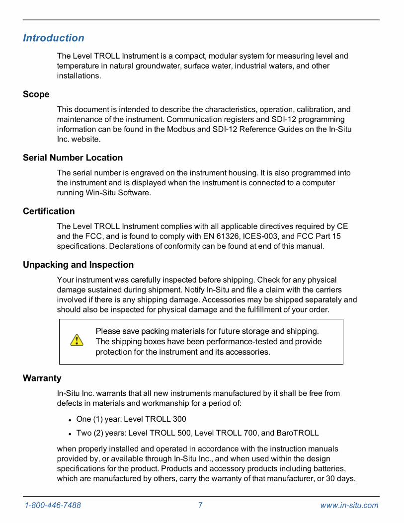
Level TROLL® 300, 500, 700, 700H Instruments
Information subject to changewithout notice. In-Situ, In-Situ logo, BaroMerge, BaroTROLL, HERMIT, iSitu, Pocket-Situ, RDO,RuggedCable, RuggedReader, TROLL, andWin-Situ are trademarks or registered trademarks of In-Situ Inc. © 2013. All rights reserved.
0052210 |Rev. 008 | 06/2013

1-800-446-7488 2 www.in-situ.com
Copyright © by In-Situ Inc. All rights reserved.
This document contains proprietary information which is protected by copyright. No partof this document may be photocopied, reproduced, or translated to another languagewithout the prior written consent of In-Situ Inc.
Mailing and ShippingAddress: Phone: 970-498-1500 (international & domestic)
In-Situ Inc.221 East Lincoln AvenueFort Collins, CO 80524U.S.A.
Fax: 970-498-1598
Internet: www.in-situ.com
Support: 800-446-7488 (U.S.A. & Canada)
In-Situ Inc. makes no warranty of any kind with regard to this material, including, but notlimited to, its fitness for a particular application. In-Situ will not be liable for errorscontained herein or for incidental or consequential damages in connection with thefurnishing, performance, or use of this material.
In no event shall In-Situ Inc. be liable for any claim for direct, incidental, orconsequential damages arising out of, or in connection with, the sale, manufacture,delivery, or use of any product.
In-Situ and the In-Situ logo, Win-Situ, TROLL, Baro Merge, BaroTROLL, HERMIT, iSitu,Pocket-Situ, RDO, RuggedCable, RuggedReader, TROLL, and Win-Situ aretrademarks or registered trademarks of In-Situ Inc. Microsoft and Windows areregistered trademarks of Microsoft Corporation. Pentium is a registered trademark ofIntel. Tefzel and Delrin are registered trademarks of E. I. DuPont de Nemours andCompany. Viton is a registered trademark of DuPont Dow Elastomers. Kellems is aregistered trademark of Hubbell Inc. Alconox is a registered trademark of AlconoxCompany. Lime-A-Way is a registered trademark of Reckitt Benckiser. iPod and iPhoneare trademarks of of Apple Inc., registered in the U.S. and other countries. TheBluetooth word mark and logos are registered trademarks owned by the Bluetooth SIG,Inc. and any use of such marks by In-Situ Inc. is under license. NIST is a registeredtrademark of the National Institute of Standards and Technology, U.S.A. Other brandnames and trademarks are property of their respective owners.
The presence of the Waste Electrical and Electronic Equipment (WEEE) marking on the productindicates that the device is not to be disposed via the municipal waste collection system of anymember state of the European Union.
For products under the requirement of WEEE directive, please contact your distributor or local In-Situ Inc. office for the proper decontamination information and take back program, which willfacilitate the proper collection, treatment, recovery, recycling, and safe disposal of the device.
0052210 | Rev. 008
1-800-446-7488 3 www.in-situ.com
Table of Contents
1 Introduction 7Scope 7Serial Number Location 7Certification 7Unpacking and Inspection 7Warranty 7Contact Information 8
2 Product Specifications 9Level TROLL 300 Instrument 9Level TROLL 500 Instrument 10Level TROLL 700 Instrument 11Level TROLL 700H Instrument 12BaroTROLL Instrument 13RuggedCable System 14Suspension Wire 14
3 About the Pressure/Level Sensor 15Absolute Pressure Sensor 15Gauged Pressure Sensor 15BaroTROLL Atmospheric Pressure Sensor 16Configuring Depth and Level for PLC or Data Logger 17
4 System Components 18Instrument 18RuggedCable System 18
Vented or Non-Vented Cable 18Jacket Options 18Customizable Cable Lengths 18Cable Termination 18
Suspension Wire 20Communication Cables 21
Cable-Connect TROLL Com Communication Device 21Direct-Connect TROLL Com Communication Device 22
Power Options 23Internal Power—Batteries 23AC Adapter 23External Power—External Battery Packs 23TROLL Battery Pack 23

1-800-446-7488 4 www.in-situ.com
TROLL Replaceable Battery Pack 24Estimated Battery Lifetime 24
Installation Accessories 25NPT Adapter 25Cable Extender 25Twist-Lock Hanger 25Bulkhead Connector 26Locking Well Cap 26Well Dock Installation Ring 27
RuggedReader Handheld PC 28Control Software 29
Win-Situ 5 Software 29Win-Situ Mobile Software 29
5 Getting Started 30Select a TROLL Com Communication Device 30Connecting RuggedCable Systems 32
Connect the Instrument to the RuggedCable 32Connect TROLL Com Communication Device to the RuggedCable System 32
Install the Software 34Win-Situ 5 Software 34Win-Situ Mobile Software 34
To update or reinstall Win-Situ Mobile use the following procedure. 34Win-Situ Sync Software 34
6 Field Deployment 35Program the Instrument 35Position the Instrument 35Verify Instrument Depth 36Secure the Cable 36Install the Desiccant 37Desiccant 37Installation Guidelines 38
Stabilization Time 39BaroTROLL Instrument Installation 40
Programming the Baro TROLL Instrument 40Installation 40
7 Software Overview 42First Screen (Data Tab) 42Home Tab 44

1-800-446-7488 5 www.in-situ.com
Logging Tab 47Sensors Tab 49Device Setup Tab 50
8 Using Win-Situ 5 Software 51Connecting an Instrument to the Software 51Selecting the Correct COM Port 51Setting the Instrument Time 52Adding a New Site 52Log Setup 52Logging Method Descriptions 53
Logging Methods for Long-Term Monitoring 53Linear 53Linear Average 53Event 53
Logging Methods for Aquifer Testing 53True Logarithmic 53Fast Linear 54Step Linear 54
About the Level Reference 54Starting a Log 55
Starting a Pending Log 55Starting a Manual Log 55
Suspending (Pausing) a Log 55Resuming a Suspended Log 56Stopping a Log 56Downloading Data to a PC 56Viewing Logged Data 57Using BaroMerge Software 58BaroMerge Input—BaroTROLL File 58BaroMerge Output 59Disconnecting an Instrument From the Software 60
9 Connect to a Data Logger or PLC Controller 60Wiring 62Analog (4-20 mA) 2 Wire 63SDI-12 3 Wire 64Modbus Master 65Modbus Master with RS232 (Converter Required) 66Power Connections 67

1-800-446-7488 6 www.in-situ.com
Communication Protocols 67Redundant Logging 68
10 Cleaning and Maintenance 69Overview 69Operating Considerations 69
Temperature 69Pressure Range 69Batteries 69
Desiccant Pack Options 70Small Desiccant 70Large Desiccant 70Outboard Desiccant 70Extra Large Desiccant 71Desiccant Refill Kit 71
Installing Desiccant with Twist-Lock Connectors 71Installing Outboard Desiccant 72Using the Desiccant Refill Kit 72Antifouling 73
TROLL Shield Nose Cone 73O-ring Inspection and Replacement 73Cleaning and Storage 74
Cleaning the Instrument 74Twist-Lock Connectors 74Storage 74
Factory Calibration and Service 75In-House Factory Calibration 75Return Materials Authorization (RMA) Form 75Obtaining Repair Service 75Guidelines for Cleaning Returned Equipment 76
11 Decontamination and Cleaning Form 7712 Troubleshooting 7813 Declaration of Conformity 80
1-800-446-7488 7 www.in-situ.com
IntroductionThe Level TROLL Instrument is a compact, modular system for measuring level andtemperature in natural groundwater, surface water, industrial waters, and otherinstallations.
ScopeThis document is intended to describe the characteristics, operation, calibration, andmaintenance of the instrument. Communication registers and SDI-12 programminginformation can be found in the Modbus and SDI-12 Reference Guides on the In-SituInc. website.
Serial Number LocationThe serial number is engraved on the instrument housing. It is also programmed intothe instrument and is displayed when the instrument is connected to a computerrunning Win-Situ Software.
CertificationThe Level TROLL Instrument complies with all applicable directives required by CEand the FCC, and is found to comply with EN 61326, ICES-003, and FCC Part 15specifications. Declarations of conformity can be found at end of this manual.
Unpacking and InspectionYour instrument was carefully inspected before shipping. Check for any physicaldamage sustained during shipment. Notify In-Situ and file a claim with the carriersinvolved if there is any shipping damage. Accessories may be shipped separately andshould also be inspected for physical damage and the fulfillment of your order.
Please save packing materials for future storage and shipping.The shipping boxes have been performance-tested and provideprotection for the instrument and its accessories.
WarrantyIn-Situ Inc. warrants that all new instruments manufactured by it shall be free fromdefects in materials and workmanship for a period of:
l One (1) year: Level TROLL 300
l Two (2) years: Level TROLL 500, Level TROLL 700, and BaroTROLL
when properly installed and operated in accordance with the instruction manualsprovided by, or available through In-Situ Inc., and when used within the designspecifications for the product. Products and accessory products including batteries,which are manufactured by others, carry the warranty of that manufacturer, or 30 days,
1-800-446-7488 8 www.in-situ.com
whichever is greater. The warranty period for all products begins on the day the productis shipped to the customer or distributor.
The complete Warranty Policy is available on the In-Situ website.
Contact Information
Mailing and ShippingAddress: Phone: 970-498-1500 (international & domestic)
In-Situ Inc.221 East Lincoln AvenueFort Collins, CO 80524U.S.A.
Fax: 970-498-1598
Internet: www.in-situ.com
Support: 800-446-7488 (U.S.A. & Canada)
In-Situ offers calibration and repair service. See page 75.

1-800-446-7488 9 www.in-situ.com
Product Specifications
Level TROLL 300 InstrumentGeneral Level TROLL 300
Temperature ranges1Operational: -20-80° C (-4-176° F)Storage: -40-80° C (-40-176° F)Calibrated: -5-50° C (23-122° F)
Diameter 2.08 cm (0.82 in.)
Length 22.9 cm (9.0 in.)
Weight 245 g (0.54 lb)
Materials Stainless steel body; Delrin nose cone
Output options Modbus/RS485, SDI-12, 4-20 mA
Battery type & life2 3.6V lithium; 10 years or 2M readings
External power 8-36 VDC
MemoryData records3Data logs
1.0 MB65,0002
Log types Linear, Fast Linear, and Event
Fastest logging rate &Modbus rate 2 per second
Fastest SDI-12 & 4-20 mAoutput rate 1 per second
Real-time clock Accurate to 1 second/24-hr period
Sensor Type/Material Piezoresistive; stainless steel
Range
Absolute (non-vented)30 psia: 10.9 m (35.8 ft)100 psia: 60.1 m (197.3 ft)300 psia: 200.7 m (658.7 ft)
Burst pressure Max. 2x range; burst > 3x range
Accuracy @ 15° C4 ±0.1% full scale (FS)
Accuracy (FS)5 ±0.2% FS
Resolution ±0.01% FS or better
Units of measure Pressure: psi, kPa, bar, mbar, mmHg, inHg, cmH2O, inH2OLevel: in, ft, mm, cm, m
Temperature Sensor
Accuracy & resolution ±0.1° C; 0.01° C or better
Units of measure Celsius or Fahrenheit
Warranty 1 yearUp to 5-year extended warranties are available for all instruments—call for details
Footnotes
1 Temperature range for non-freezing liquids2 Typical battery life when used within the factory-calibrated temperature range.3 1 data record = date/time plus 2 parameters logged (no wrapping) from device within the factory-calibrated temperature range4 Across factory-calibrated pressure range5 Across factory-calibrated pressure and temperature rangesSpecifications are subject to change without notice.Delrin is a registered trademark of E.I. du Pont de Nemours and Company.

1-800-446-7488 10 www.in-situ.com
Level TROLL 500 InstrumentGeneral Level TROLL 500
Temperature ranges1Operational: -20-80° C (-4-176° F)Storage: -40-80° C (-40-176° F)Calibrated: -5-50° C (23-122° F)
Diameter 1.83 cm (0.72 in.)
Length 21.6 cm (8.5 in.)
Weight 197 g (0.43 lb)
Materials Titanium body; Delrin nose cone
Output options Modbus/RS485, SDI-12, 4-20 mA
Battery type & life2 3.6V lithium; 10 years or 2M readings
External power 8-36 VDC
MemoryData records3Data logs
2.0 MB130,00050
Log types Linear, Fast Linear, and Event
Fastest logging rate & Modbus rate 2 per second
Fastest SDI-12 & 4-20 mA output rate 1 per second
Real-time clock Accurate to 1 second/24-hr period
Sensor Type/Material Piezoresistive; titanium
Range
Absolute (non-vented)30 psia: 10.9 m (35.8 ft)100 psia: 60.1 m (197.3 ft)300 psia: 200.7 m (658.7 ft)500 psia: 341.3 m (1120 ft)
Gauged (vented)5 psig: 3.5 m (11.5 ft)15 psig: 11 m (35 ft)30 psig: 21 m (69 ft)100 psig: 70 m (231 ft)300 psig: 210 m (692 ft)500 psig: 351 m (1153 ft)
Burst pressure Max. 2x range; burst > 3x range
Accuracy @ 15° C4 ±0.05% FS
Accuracy (FS)5 ±0.1% FS
Resolution ±0.005% FS or better
Units of measure Pressure: psi, kPa, bar, mbar, mmHg, inHg, cmH2O, inH2OLevel: in, ft, mm, cm, m
Temperature Sensor
Accuracy & resolution ±0.1° C; 0.01° C or better
Units of measure Celsius or Fahrenheit
Warranty 2 yearsUp to 5-year extended warranties are available for all instruments—call for details
Footnotes See See page 9.
1-800-446-7488 11 www.in-situ.com
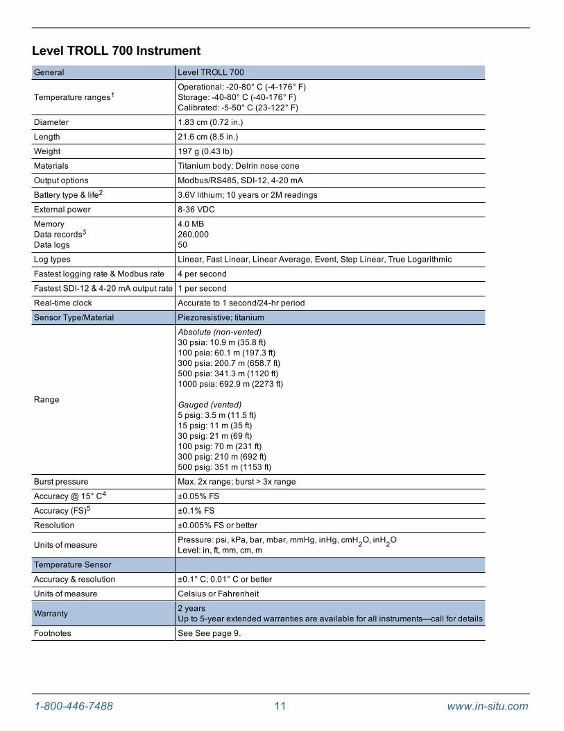
Level TROLL 700 InstrumentGeneral Level TROLL 700
Temperature ranges1Operational: -20-80° C (-4-176° F)Storage: -40-80° C (-40-176° F)Calibrated: -5-50° C (23-122° F)
Diameter 1.83 cm (0.72 in.)
Length 21.6 cm (8.5 in.)
Weight 197 g (0.43 lb)
Materials Titanium body; Delrin nose cone
Output options Modbus/RS485, SDI-12, 4-20 mA
Battery type & life2 3.6V lithium; 10 years or 2M readings
External power 8-36 VDC
MemoryData records3Data logs
4.0 MB260,00050
Log types Linear, Fast Linear, Linear Average, Event, Step Linear, True Logarithmic
Fastest logging rate & Modbus rate 4 per second
Fastest SDI-12 & 4-20 mA output rate 1 per second
Real-time clock Accurate to 1 second/24-hr period
Sensor Type/Material Piezoresistive; titanium
Range
Absolute (non-vented)30 psia: 10.9 m (35.8 ft)100 psia: 60.1 m (197.3 ft)300 psia: 200.7 m (658.7 ft)500 psia: 341.3 m (1120 ft)1000 psia: 692.9 m (2273 ft)
Gauged (vented)5 psig: 3.5 m (11.5 ft)15 psig: 11 m (35 ft)30 psig: 21 m (69 ft)100 psig: 70 m (231 ft)300 psig: 210 m (692 ft)500 psig: 351 m (1153 ft)
Burst pressure Max. 2x range; burst > 3x range
Accuracy @ 15° C4 ±0.05% FS
Accuracy (FS)5 ±0.1% FS
Resolution ±0.005% FS or better
Units of measure Pressure: psi, kPa, bar, mbar, mmHg, inHg, cmH2O, inH2OLevel: in, ft, mm, cm, m
Temperature Sensor
Accuracy & resolution ±0.1° C; 0.01° C or better
Units of measure Celsius or Fahrenheit
Warranty 2 yearsUp to 5-year extended warranties are available for all instruments—call for details
Footnotes See See page 9.

1-800-446-7488 12 www.in-situ.com
Level TROLL 700H InstrumentComply with the Office of Surface Water by using the most accurate pressuretransducer available. The Level TROLL 700H meets the surface-water specification of±0.01 foot.
For accuracy under all operating conditions, instruments are calibrated over the fullpressure and temperature range. Each instrument includes a serialized, NIST-traceablecalibration report.
General Level TROLL 700H
Temperature ranges1Operational: -20-80° C (-4-176° F)Storage: -40-80° C (-40-176° F)Calibrated: 0-40° C (32-104° F)
Diameter 1.83 cm (0.72 in.)
Length 21.6 cm (8.5 in.)
Weight 197 g (0.43 lb)
Materials Titanium body; Delrin nose cone
Output options Modbus/RS485, SDI-12, 4-20 mA
Battery type & life2 3.6V lithium; 5 years or 2M readings
External power 8-36 VDC
MemoryData records3Data logs
4.0 MB260,00050
Log types Linear, Fast Linear, Linear Average, Event, Step Linear, True Logarithmic
Fastest logging rate & Modbus rate 4 per second
Fastest SDI-12 & 4-20 mA output rate 1 per second
Real-time clock Accurate to 1 second/24-hr period
Pressure Sensor Type/Material Piezoresistive; titanium
Range Gauged (vented)15 psig: 11 m (35 ft)
Burst pressure Max. 2x range; burst > 3x range
Accuracy4 ±0.01 foot up to 10 ft and ±0.1% of reading > 10 ft
Resolution ±0.005% FS or better
Units of measure Pressure: psi, kPa, bar, mbar, mmHg, inHg, cmH2O, inH2OLevel: mm, cm, m, in, ft,
Temperature Sensor
Accuracy & resolution ±0.1° C; 0.01° C or better
Units of measure Celsius or Fahrenheit
Warranty 2 yearsUp to 5-year extended warranties are available for all instruments—call for details
Footnotes See See page 9.

1-800-446-7488 13 www.in-situ.com
BaroTROLL InstrumentThe titanium BaroTROLL measures and logs barometric pressure and temperature.Use the BaroTROLL in conjunction with non-vented In-Situ Instruments.
Win-Situ BaroMerge Software simplifies post-correction of water level data byautomatically subtracting barometric readings from data collected by a non-ventedinstrument to compensate for changes in pressure due to barometric fluctuations.
General BaroTROLL
Temperature ranges1Operational: -20-80° C (-4-176° F)Storage: -40-80° C (-40-176° F)Calibrated: -5-50° C (23-122° F)
Diameter 1.83 cm (0.72 in.)
Length 21.6 cm (8.5 in.)
Weight 197 g (0.43 lb)
Materials Titanium body; Delrin nose cone
Output options Modbus/RS485, SDI-12, 4-20 mA
Battery type & life2 3.6V lithium; 10 years or 2M readings
External power 8-36 VDC
MemoryData records3Data logs
1.0 MB65,0002
Log types Linear
Fastest logging rate & Modbus rate 1 per minute
Fastest SDI-12 & 4-20 mA output rate 1 per second
Real-time clock Accurate to 1 second/24-hr period
Sensor Type/Material Piezoresistive; titanium
Range 0 to 16.5 psi; 0 to 1.14 bar
Burst pressure Vaccum/over-pressure above 16.5 psi damages sensor
Accuracy @ 15° C4 ±0.1% FS
Accuracy (FS)5 ±0.2% FS
Resolution ±0.005% FS or better
Units of measure Pressure: psi, kPa, bar, mbar, mmHg, inHg, cmH2O, inH2O
Temperature Sensor
Accuracy & resolution ±0.1° C; 0.01° C or better
Units of measure Celsius or Fahrenheit
Warranty 2 yearsUp to 5-year extended warranties are available for all instruments—call for details
Footnotes See See page 9.

1-800-446-7488 14 www.in-situ.com
RuggedCable SystemGeneral RuggedCable System
Operating temp. range -25° to 80° C (-13° to 176° F)
Jacket options TPU (thermoplastic polyurethane)Tefzel (ETFE fluoropolymer; generic equivalent to Teflon)
Vent options Non-vented (absolute)Vented (gauged) with desiccant (used to mitigate moisture/humidity)
Conductors 6 conductors, 24 AWG, polypropylene insulation
Cable diameter TPU: 6.7 mm (0.265 in.)Tefzel: 6.35 mm (0.25 in.)
Connector diameter 18. 5 mm (0.73 in.)
Weight
Non-vented, TPU: 16 kg/300 m (35.6 lbs/1,000 ft)Non-vented, Tefzel: 14 kg/300 m (32 lbs/1,000 ft)Vented, TPU: 14 kg/300 m (32 lbs/1,000 ft)Vented, Tefzel: 14 kg/300 m (32 lbs/1,000 ft)
Minimum bend radius 2X cable diameter (13.5 mm; 0.54 in.)
Break strength 127 kg (280 lbs)
Maximum cable length 1,219 m (4,000 ft) for RS485
Desiccant pack(required for ventedsystems)
Large and extra large desiccant packs available with titanium, ABS, or stripped-and-tinnedtermination.
Warranty 2 years
Specifications are subject to change without notice.
Suspension WireGeneral Suspension Wire
Material 304 stainless steel, 7 x 7 strand
Coating 15 mil polyester elastomer insulation
Weight 0.28 kg / 30 m (0.60 lb / 100 ft)
Break strength 122 kg (270 lb) with proper clip tightening
Specifications are subject to change without notice.
1-800-446-7488 15 www.in-situ.com
About the Pressure/Level SensorA pressure transducer senses changes in pressure, measured in force per square unitof surface area, exerted by water or other fluid on an internal media-isolated straingauge. In-Situ Inc. offers instruments with either absolute (non-vented) or gauged(vented) pressure sensors.
The "Absolute vs. Gauged: Comparing Absolute and GaugedPressure Sensors" technical note describes the differencebetween absolute and gauged pressure sensors and explains theproper use of each type of sensor in different applications. Seewww.in-situ.com/technical_notes.
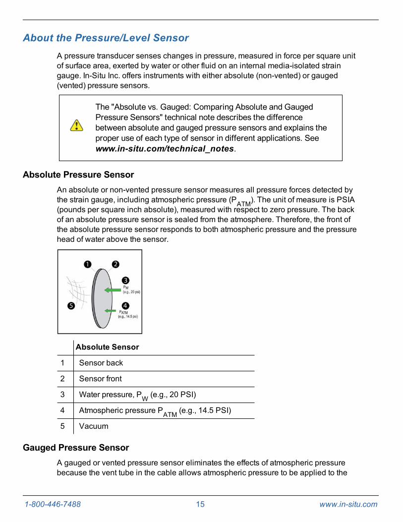
Absolute Pressure SensorAn absolute or non-vented pressure sensor measures all pressure forces detected bythe strain gauge, including atmospheric pressure (PATM). The unit of measure is PSIA(pounds per square inch absolute), measured with respect to zero pressure. The backof an absolute pressure sensor is sealed from the atmosphere. Therefore, the front ofthe absolute pressure sensor responds to both atmospheric pressure and the pressurehead of water above the sensor.
Absolute Sensor
1 Sensor back
2 Sensor front
3 Water pressure, PW (e.g., 20 PSI)
4 Atmospheric pressure PATM (e.g., 14.5 PSI)
5 Vacuum
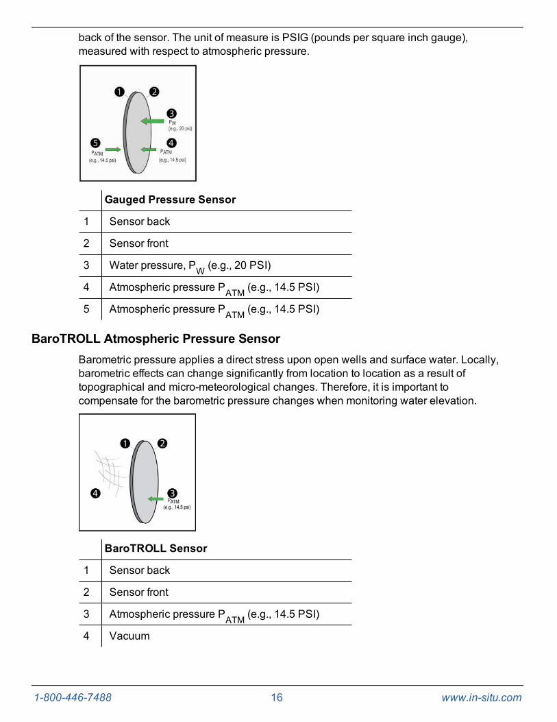
Gauged Pressure SensorA gauged or vented pressure sensor eliminates the effects of atmospheric pressurebecause the vent tube in the cable allows atmospheric pressure to be applied to the
1-800-446-7488 16 www.in-situ.com
back of the sensor. The unit of measure is PSIG (pounds per square inch gauge),measured with respect to atmospheric pressure.
Gauged Pressure Sensor
1 Sensor back
2 Sensor front
3 Water pressure, PW (e.g., 20 PSI)
4 Atmospheric pressure PATM (e.g., 14.5 PSI)
5 Atmospheric pressure PATM (e.g., 14.5 PSI)
BaroTROLL Atmospheric Pressure SensorBarometric pressure applies a direct stress upon open wells and surface water. Locally,barometric effects can change significantly from location to location as a result oftopographical and micro-meteorological changes. Therefore, it is important tocompensate for the barometric pressure changes when monitoring water elevation.
BaroTROLL Sensor
1 Sensor back
2 Sensor front
3 Atmospheric pressure PATM (e.g., 14.5 PSI)
4 Vacuum
1-800-446-7488 17 www.in-situ.com
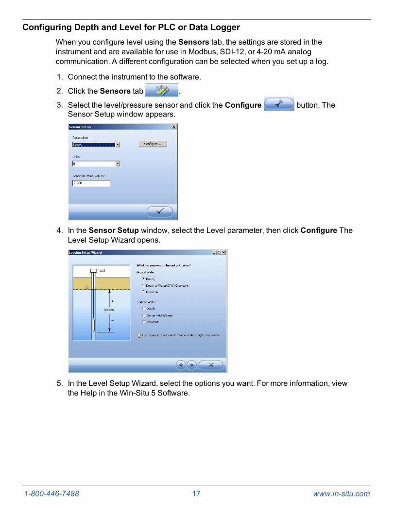
Configuring Depth and Level for PLC or Data LoggerWhen you configure level using the Sensors tab, the settings are stored in theinstrument and are available for use in Modbus, SDI-12, or 4-20 mA analogcommunication. A different configuration can be selected when you set up a log.
1. Connect the instrument to the software.
2. Click the Sensors tab .
3. Select the level/pressure sensor and click the Configure button. TheSensor Setup window appears.
4. In the Sensor Setup window, select the Level parameter, then click Configure TheLevel Setup Wizard opens.
5. In the Level Setup Wizard, select the options you want. For more information, viewthe Help in the Win-Situ 5 Software.

1-800-446-7488 18 www.in-situ.com
System Components
InstrumentThe Level TROLL Instrument is completely sealed and contains no user-serviceableparts. The instrument includes pressure and temperature sensors, a real-time clock,microprocessor, sealed lithium battery, data logger, and memory. Options include avented or non-vented pressure sensor in a variety of ranges.
RuggedCable SystemRuggedCable Systems are custom-built, durable, direct-read cables that include thefollowing items.
l Titanium twist-lock connectors for quick, reliable connections to the instrument,desiccant, and communication cable
l Metal shield beneath the cable jacket to prevent electrical interferences
l Kellems grip for secure instrument deployment
l Small desiccant for vented systems (for storage only)
Non-vented cables are marked with VF, which means vent free.
Vented or Non-Vented Cable
Vented cable is used with vented pressure sensors to produce gauged measurements.The cable vent tube ensures that atmospheric pressure is applied to the back of thesensor diaphragm.
Non-vented cable is used with non-vented instruments for absolute measurements.Compensate absolute measurements by using a BaroTROLL Instrument and Win-SituBaro Merge Software.
Vented cable is shipped with a small desiccant to protect againstcondensation. Larger desiccants are necessary for deployment.
Jacket Options
Tefzel (vented) or thermoplastic polyurethane (TPU, vented or non-vented)
Customizable Cable Lengths
Cables can be ordered up to 1,219 m (4,000 ft).
Cable Termination
Cables can be ordered with a twist-lock termination (female connector) on both endsthat connect to the instrument, the TROLL Com Communication Device, desiccant, and

1-800-446-7488 19 www.in-situ.com
other accessories.
Cables can also be ordered with stripped-and-tinned termination for wiring to a datalogger or controller using SDI-12, analog (4-20 mA), or Modbus communicationprotocol.
1 RuggedCable System with female to female connectors2 Stripped-and-tinned RuggedCable System with female connector
3Stripped-and-tinned RuggedCable System with male connector(short length that converts a cable with a twist-lock connector to astripped-and-tinned cable)
1-800-446-7488 20 www.in-situ.com
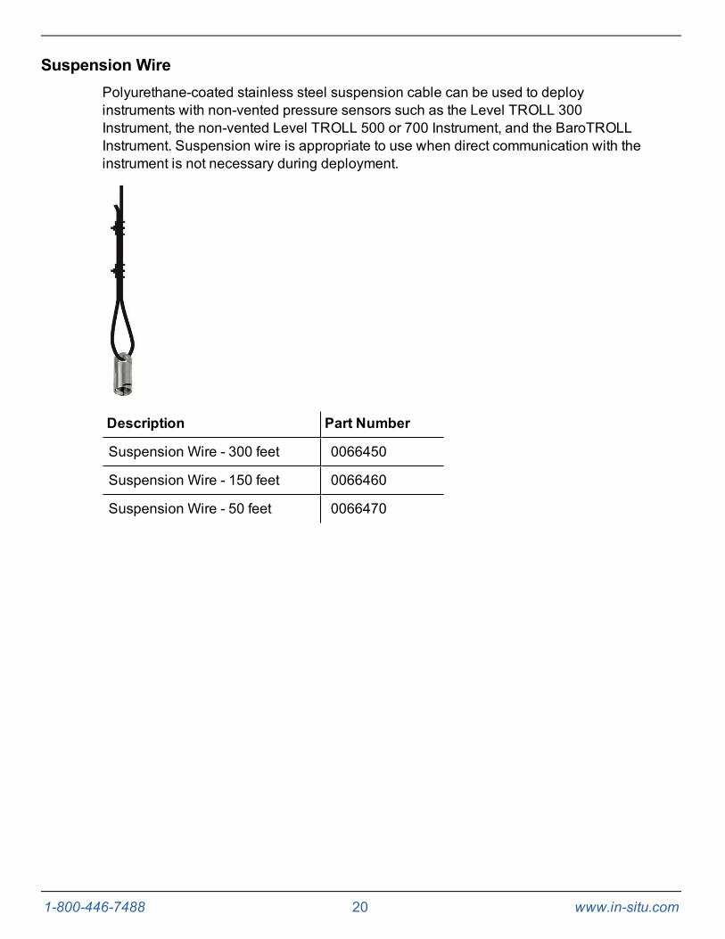
Suspension WirePolyurethane-coated stainless steel suspension cable can be used to deployinstruments with non-vented pressure sensors such as the Level TROLL 300Instrument, the non-vented Level TROLL 500 or 700 Instrument, and the BaroTROLLInstrument. Suspension wire is appropriate to use when direct communication with theinstrument is not necessary during deployment.
Description Part Number
Suspension Wire - 300 feet 0066450
Suspension Wire - 150 feet 0066460
Suspension Wire - 50 feet 0066470

1-800-446-7488 21 www.in-situ.com
Communication CablesThe TROLL Com Communication Device provides an interface between the instrumentand a desktop/laptop PC or the RuggedReader Handheld PC for calibrating andprogramming the instrument and for profiling and downloading data. The TROLL ComCommunication Device is offered in either a cable-connect or direct-connectconfiguration including a 0.9 m (3 ft) vented polyurethane cable, external power inputjack, and vent with replaceable membrane.
Cable-Connect TROLL Com Communication Device
The Cable-Connect TROLL Com Communication Device connects to an instrument'sRuggedCable System and to a serial or USB port. This communication cable isweatherproof and withstands temporary immersion in water (IP67 compliant).
1 RS232 TROLL Com, Cable-Connect, part number 0056140 (pictured) or USBTROLL Com, Cable-Connect, part number 0052500
2 External power input3 Vent4 Twist-lock connector
1-800-446-7488 22 www.in-situ.com
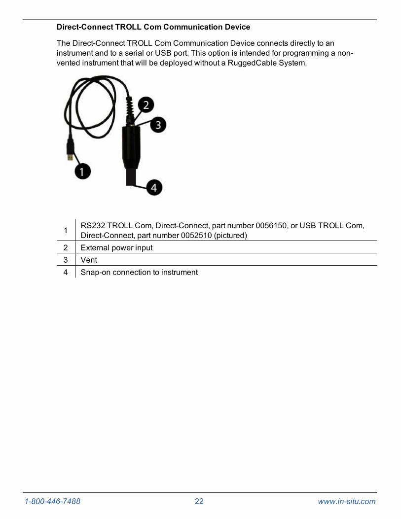
Direct-Connect TROLL Com Communication Device
The Direct-Connect TROLL Com Communication Device connects directly to aninstrument and to a serial or USB port. This option is intended for programming a non-vented instrument that will be deployed without a RuggedCable System.
1 RS232 TROLL Com, Direct-Connect, part number 0056150, or USB TROLL Com,Direct-Connect, part number 0052510 (pictured)
2 External power input3 Vent4 Snap-on connection to instrument
1-800-446-7488 23 www.in-situ.com
Power Options
Internal Power—Batteries
Internal batteries are not user-replaceable. The approximate percentage of the powerremaining in an internal battery is displayed on the Home Screen when an instrument isconnected to Win-Situ Software.
The instrument is powered by 3.6 VDC, supplied by a sealed, non-replaceable AAlithium battery. Battery life depends on sampling speed. The battery typically lasts for10 years or 2,000,000 readings, whichever occurs first.
When an instrument is wired to a data logger or PLC controller, power to the instrumentis supplied by the data logger or controller.
AC Adapter
The AC adapter provides 24 VDC, 0.75 A, AC input 100-250 V and includes a NorthAmerican power cord. The TROLL Com Communication Device includes an externalpower input port for connection to the AC adapter.
Description Part Number
AC Adapter 24 VDC 0052440
Use only In-Situ Inc.'s AC adapter. Damage to the instrumentcaused by the use of third-party converters is not covered by thewarranty.
External Power—External Battery Packs
External battery packs can significantly increase the life of an instrument, either forlong-term deployments or to preserve an aging instrument.
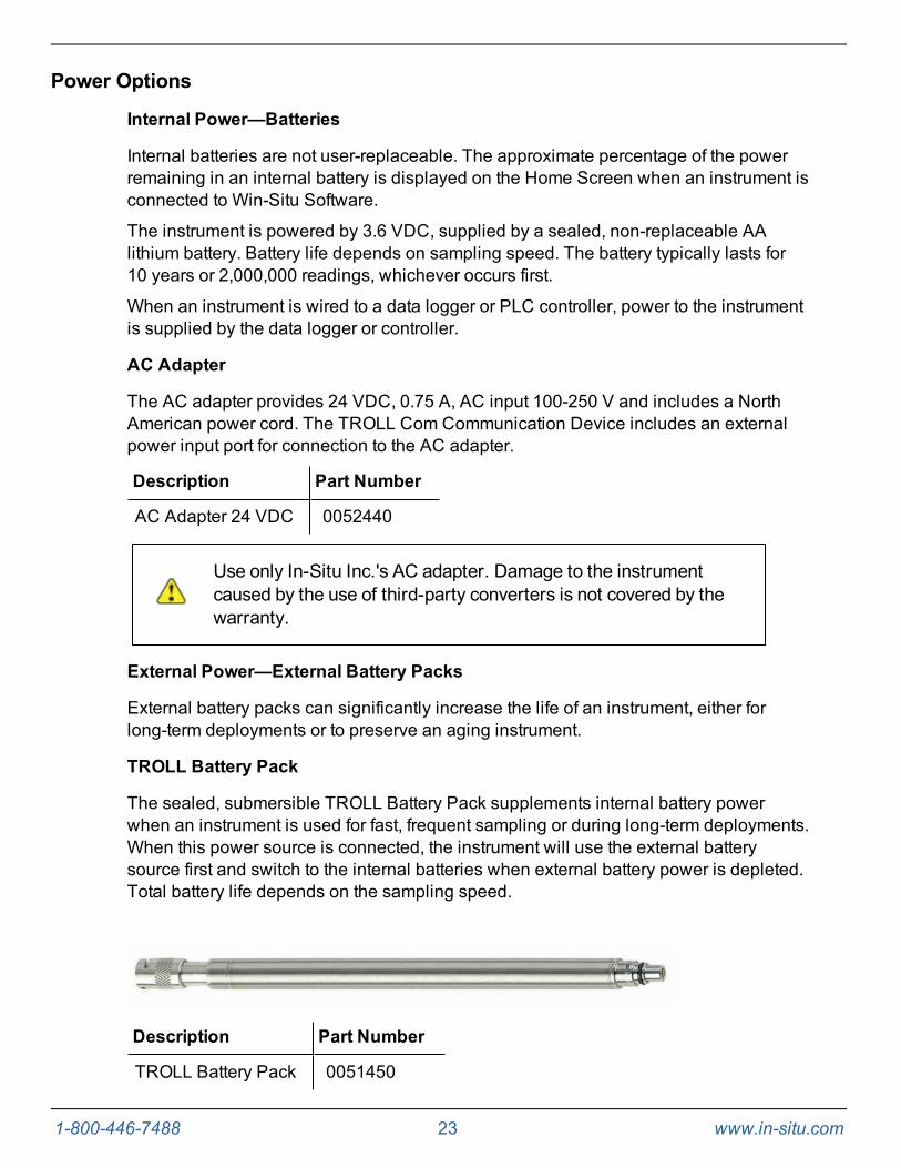
TROLL Battery Pack
The sealed, submersible TROLL Battery Pack supplements internal battery powerwhen an instrument is used for fast, frequent sampling or during long-term deployments.When this power source is connected, the instrument will use the external batterysource first and switch to the internal batteries when external battery power is depleted.Total battery life depends on the sampling speed.
Description Part Number
TROLL Battery Pack 0051450
1-800-446-7488 24 www.in-situ.com
The sealed, submersible TROLL Battery Pack supplies 14.4 V. When this powersource is connected, the Level TROLL will use the external battery source first andswitch to the internal batteries when external battery power is depleted.
0.5 second sampling interval 1.2 months
1 second sampling interval 2.3 months
1 minute (or longer) sampling interval 1 year
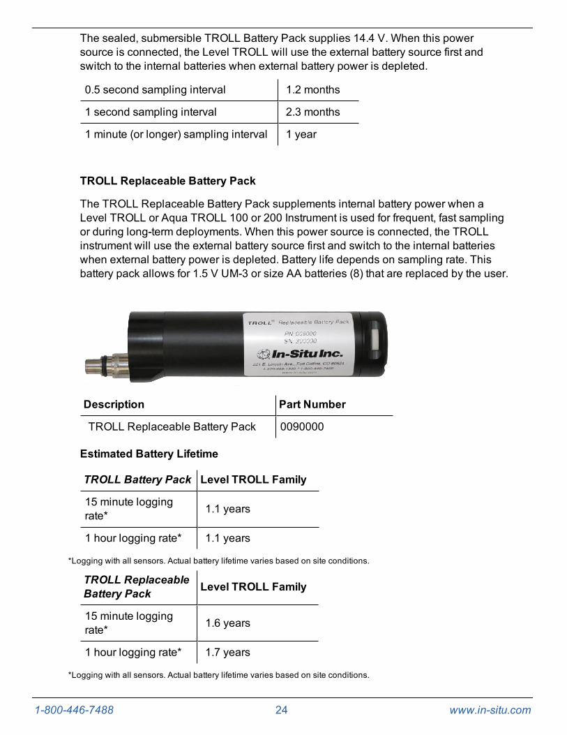
TROLL Replaceable Battery Pack
The TROLL Replaceable Battery Pack supplements internal battery power when aLevel TROLL or Aqua TROLL 100 or 200 Instrument is used for frequent, fast samplingor during long-term deployments. When this power source is connected, the TROLLinstrument will use the external battery source first and switch to the internal batterieswhen external battery power is depleted. Battery life depends on sampling rate. Thisbattery pack allows for 1.5 V UM-3 or size AA batteries (8) that are replaced by the user.
Description Part Number
TROLL Replaceable Battery Pack 0090000
Estimated Battery Lifetime
TROLL Battery Pack Level TROLL Family
15 minute loggingrate* 1.1 years
1 hour logging rate* 1.1 years
*Logging with all sensors. Actual battery lifetime varies based on site conditions.
TROLL ReplaceableBattery Pack Level TROLL Family
15 minute loggingrate* 1.6 years
1 hour logging rate* 1.7 years
*Logging with all sensors. Actual battery lifetime varies based on site conditions.
1-800-446-7488 25 www.in-situ.com
Installation Accessories
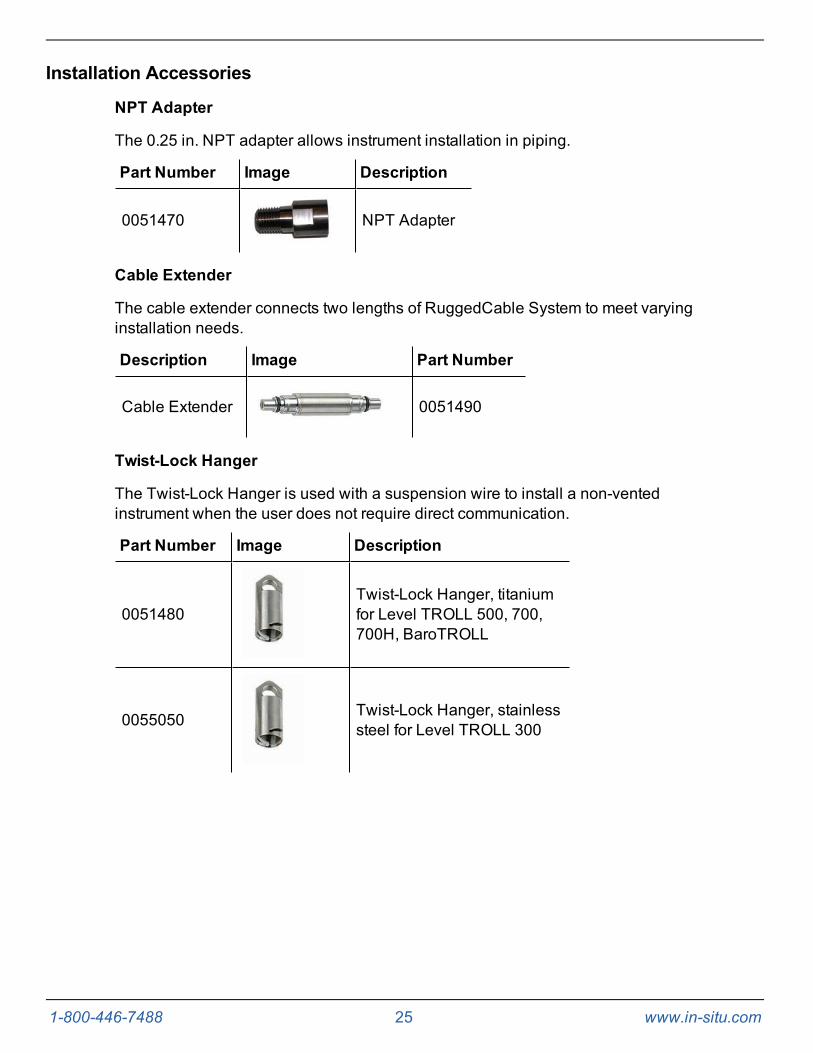
NPT Adapter
The 0.25 in. NPT adapter allows instrument installation in piping.
Part Number Image Description
0051470 NPT Adapter
Cable Extender
The cable extender connects two lengths of RuggedCable System to meet varyinginstallation needs.
Description Image Part Number
Cable Extender 0051490
Twist-Lock Hanger
The Twist-Lock Hanger is used with a suspension wire to install a non-ventedinstrument when the user does not require direct communication.
Part Number Image Description
0051480Twist-Lock Hanger, titaniumfor Level TROLL 500, 700,700H, BaroTROLL
0055050 Twist-Lock Hanger, stainlesssteel for Level TROLL 300

1-800-446-7488 26 www.in-situ.com
Bulkhead Connector
The panel-mounted bulkhead connector provides connection between RuggedCableSystem and a controller panel.
Part Number Image Description
0053240 Bulkhead Connector
Locking Well Cap
Description Part Number
Locking Well Cap, 2" 0020360
Locking Well Cap, 2" vented 0020370
Locking Well Cap, 4" 0020380
Locking Well Cap, 4" vented 0020390

1-800-446-7488 27 www.in-situ.com
Well Dock Installation Ring
The well dock installation ring provides installation support for 2", 4", and 6" wellcasings.
Description Part Number
Well Dock Installation Ring 2" 0004690
Well Dock Installation Ring 4" 0004700
Well Dock Installation Ring 6" 0020650

1-800-446-7488 28 www.in-situ.com
RuggedReader Handheld PCThe RuggedReader Handheld PC is a multi-purpose, field-ready computer designedfor Windows Mobile operating systems.
Win-Situ Mobile Software provides the features of Win-Situ 5 Software on theRuggedReader.
Description Part Number
RuggedReader Only (520 MHz) - RuggedReader only (does notinclude software or communications cable) 0057710
RuggedReader Kit (includes 520 MHz RuggedReader, CableConnect TROLL Com, and Win-Situ Mobile Software) 0057720

1-800-446-7488 29 www.in-situ.com
Control Software
Win-Situ 5 Software
Win-Situ 5 Software is the control and calibration software for the Level TROLL, AquaTROLL, and Rugged TROLL Instruments.
Win-Situ 5 Software provides instrument control for direct readings and profiling, long-term data logging, data downloads, data viewing, data export to spreadsheet programs,selecting units, displaying options, and tracking battery/memory usage. Win-Situ 5 Plusenables configuration of networks and telemetry.
Requirements
l 400 MHz Pentium II processor
l 128 MB RAM
l 100 MB free disk space
l Internet Explorer 6.01 or higher
l Windows 2000 Professional SP4 or higher, or Windows XP Professional SP2 orhigher, or Windows Vista SP1 or higher
l CD-ROM drive, and a serial or USB communications port.
Win-Situ Mobile Software
Win-Situ Mobile Software provides the features and functions of Win-Situ 5 on a field-portable platform.
Requirements
l In-Situ RuggedReader Handheld PC with Microsoft Windows Mobile operatingsystem
l Windows Mobile 5 or later
l Serial communications port
l At least 16 MB for data storage (SD card, CF card, or the device’s built-in non-volatile memory).
For installation and file exchange, Windows 7 requiresWindows Mobile Device Center to be installed on the computer.Earlier versions on Windows require Microsoft ActiveSync.
1-800-446-7488 30 www.in-situ.com
Getting StartedThis section provides an overview of the initial steps necessary to prepare theinstrument to log data.
l Select the appropriate TROLL Com Communication Device. This determines thehardware connections, and may influence the software installation. The drawingon the following page shows the function of the different TROLL ComCommunication Device models.
l Install the software.
l Connect the hardware.
l Open the software and establish communication with the instrument.
Select a TROLL Com Communication DeviceThe subsequent figure shows the function and connection features of the TROLL ComCommunication Device models.
l A Direct-Connect TROLL Commight be preferred for programming an instrumentthat will be deployed on a suspension cable.
l A RuggedCable System and a Cable-Connect TROLL Com are required if youintend to communicate with the instrument while it is deployed. However, you canprogram the instrument with any TROLL Com.
l A serial (RS232) TROLL Com is required for use with a RuggedReader HandheldPC.

1-800-446-7488 31 www.in-situ.com
1 Serial port on a PC/laptop and RuggedReader Handheld PC
2 Direct-Connect TROLL Com Communication Device, serialconnection, programming only, not submersible
3 Cable-Connect TROLL Com Communication Device, serialconnection, for field use
4 USB port on a PC/laptop
5 Direct-Connect TROLL Com Communication Device, USBconnection, programming only, not submersible
6 Cable-Connect TROLL Com Communication Device, USBconnection, for field use
1-800-446-7488 32 www.in-situ.com
Connecting RuggedCable Systems
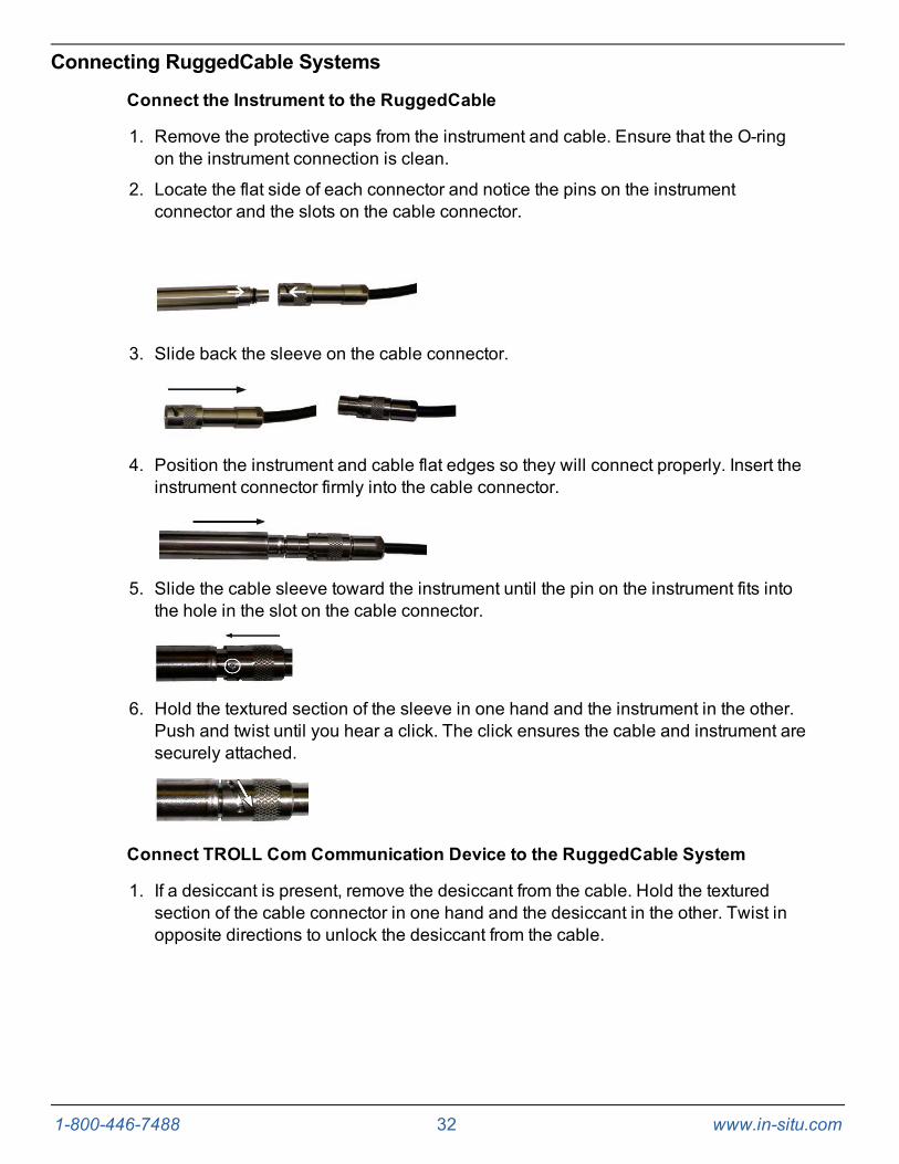
Connect the Instrument to the RuggedCable
1. Remove the protective caps from the instrument and cable. Ensure that the O-ringon the instrument connection is clean.
2. Locate the flat side of each connector and notice the pins on the instrumentconnector and the slots on the cable connector.
3. Slide back the sleeve on the cable connector.
4. Position the instrument and cable flat edges so they will connect properly. Insert theinstrument connector firmly into the cable connector.
5. Slide the cable sleeve toward the instrument until the pin on the instrument fits intothe hole in the slot on the cable connector.
6. Hold the textured section of the sleeve in one hand and the instrument in the other.Push and twist until you hear a click. The click ensures the cable and instrument aresecurely attached.
Connect TROLL Com Communication Device to the RuggedCable System
1. If a desiccant is present, remove the desiccant from the cable. Hold the texturedsection of the cable connector in one hand and the desiccant in the other. Twist inopposite directions to unlock the desiccant from the cable.

1-800-446-7488 33 www.in-situ.com
2. Position the TROLL Com and cable flat edges so they will connect properly. Insertthe TROLL Com connector firmly into the cable connector.
3. Hold the textured section of the sleeve in one hand and the TROLL Com in theother. Push and twist until you hear a click. The click ensures the cable and TROLLCom are securely attached.

1-800-446-7488 34 www.in-situ.com
Install the Software
Win-Situ 5 Software
Install Win-Situ 5 Software from the In-Situ software/resource CD or from the In-Situwebsite. Click the Win-Situ 5 link, and follow the instructions to install Win-Situ 5 to yourlocal hard drive.
USB TROLL Com Drivers
If you are using a USB TROLL Com Communication Device, be sure to select theoption "Install USB TROLL Com Drivers" during the Win-Situ 5 installation. Two driverswill be loaded to your hard drive, one for the USB TROLL Com, one for the USBTROLL Com serial port.
Win-Situ Mobile Software
Win-Situ Mobile provides the features and functions of Win-Situ 5 on a field-portableplatform. The RuggedReader is shipped with the software already installed.
To update or reinstall Win-Situ Mobile use the following procedure.
1. Install the desktop component of Win-Situ Mobile on a PC from the CD or website.The desktop component is called the Win-Situ Software Manager, and is needed toinstall Win-Situ Mobile on the RuggedReader.
2. Click the Win-Situ Mobile link and follow the instructions to install the Win-SituSoftware Manager to your local hard drive.
If using Windows 7, ensure that Windows Mobile Device Center isinstalled. If using an operating system prior to Windows 7, ensurethat Microsoft ActiveSync is installed on the desktop or laptop PCand a Guest connection or partnership has been establishedbetween the computers.
3. Connect the RuggedReader to the PC, establish a connection in MicrosoftActiveSync, open the Win-Situ Software Manager, and follow the instructions toinstall Win-Situ Mobile on the RuggedReader.
Win-Situ Sync Software
To synchronize log files from the RuggedReader to a PC after collecting data in thefield, install Win-Situ Sync from the CD or website.
1-800-446-7488 35 www.in-situ.com
Field Deployment
Program the InstrumentIn order to set up a log or download data, you must connect the instrument to acomputer running Win-Situ 5 Software, or a RuggedReader Handheld PC running Win-Situ Mobile. See page 51.
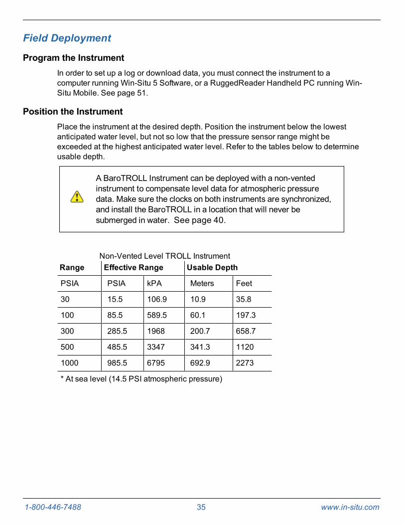
Position the InstrumentPlace the instrument at the desired depth. Position the instrument below the lowestanticipated water level, but not so low that the pressure sensor range might beexceeded at the highest anticipated water level. Refer to the tables below to determineusable depth.
A BaroTROLL Instrument can be deployed with a non-ventedinstrument to compensate level data for atmospheric pressuredata. Make sure the clocks on both instruments are synchronized,and install the BaroTROLL in a location that will never besubmerged in water. See page 40.
Range Effective Range Usable Depth
PSIA PSIA kPA Meters Feet
30 15.5 106.9 10.9 35.8
100 85.5 589.5 60.1 197.3
300 285.5 1968 200.7 658.7
500 485.5 3347 341.3 1120
1000 985.5 6795 692.9 2273
* At sea level (14.5 PSI atmospheric pressure)
Non-Vented Level TROLL Instrument

1-800-446-7488 36 www.in-situ.com
Range Usable Depth
PSIG kPA Meters Feet
5 34.5 3.5 11.5
15 103.4 11 35
30 206.8 21 69
100 689.5 70 231
300 2068 210 692
500 3447 351 1153
Vented Level TROLL Instrument
Verify Instrument DepthAfter you have installed the instrument, it is possible to connect the instrument to acomputer or RuggedReader, open the software, and take a reading to verify theinstallation position. If the reading confirms that the instrument is in the correct position,you can secure it as described below.
During log setup there was an option to "Remind Me Later" for setting a level reference.If you set the log to remind you later, ensure that the instrument is submerged and setthe level reference when prompted. See page 54.
Secure the CableThe RuggedCable System includes a Kellems grip near the up-hole end. You cancompress the wire mesh and slide the grip to the desired location on the cable. Pull onthe grip to tighten it on the cable.
Use the loop on the Kellems grip to anchor the cable to a convenient stationary objectsuch as the In-Situ well dock installation ring. To install the Kellems grip to theinstallation ring, insert the loop into the locking clip on the well dock and position theassembly at the top of a well casing.

1-800-446-7488 37 www.in-situ.com
1 Well Dock Installation Ring
2 Kellems Grip
3 Instrument Installed in Well
Install the Desiccant
Vented cable must be protected with a desiccant pack that isproperly sized for site conditions.
DesiccantDesiccant protects electronics from condensation, which can cause irreparable damageand loss of data. Indicating desiccant changes from blue to pink as it becomessaturated with moisture.
Desiccant stages (from left)New, nearly expired (replace now), expired

1-800-446-7488 38 www.in-situ.com
It is extremely important to use a properly-sized desiccant for your deployment and tochange desiccant often. Desiccant should be changed before the entire volume hasturned pink, and you should use enough desiccant to effectively keep cables,instruments, and electrical boards dry until your next scheduled maintenance.Desiccant life span is dependent on site conditions.
Installation Guidelines
l Never let the instrument fall freely down a well. Doing so will damage the sensor.
l After you have installed the instrument, verify the water level reading. Move theinstrument and take another reading to ensure that the instrument showsreasonable change. The instrument could be wedged against the well casing witha loop of cable hanging below. An instrument in such a position could becomedislodged and move while it is logging data, which would record a false change inthe water level.
l For accurate measurements, the instrument should remain immobile while it islogging data.
l Make sure that the uphole cable end is protected. The vented cable must beprotected with a desiccant, and the non-vented cable must be protected with adust cap. The uphole cable end must be positioned above the highest anticipatedwater level. Avoid placing this end in a location that might flood.
l Do not deploy instruments in such a way that ice may form on or near the sensoror cable connections. Ice formation is a powerful expansive force that can over-pressurize the sensor or otherwise cause damage. Damage associated with iceformation is not covered by the instrument warranty.
l Do not allow vented cable to bend enough to obstruct the internal vent tube. Therecommended bend radius is 13.5 mm (0.54 in), which is twice the cablediameter.
R Bend radius 13.5 mm (0.54 in)D Cable diameter

1-800-446-7488 39 www.in-situ.com
Stabilization Time
After you have installed the instrument, allow it to stabilize to the environment for about10 minutes before logging data. The T95 response time for temperature is less than 9minutes.
A generous stabilization time is always desirable, especially in long-term deployments.Even though the cable is shielded, temperature stabilization, stretching, and relaxingcan cause changes to readings.
If you intend to monitor water levels to the instrument's stringentaccuracy specifications, allow up to 60 minutes for the probe andcable to stabilize to the environment.

1-800-446-7488 40 www.in-situ.com
BaroTROLL Instrument InstallationThe BaroTROLL Instrument is designed to log barometric pressure from 0 to 16.5 PSIA(1.14 bar, 33.59 inHg) at the surface near a submerged non-vented Level TROLLInstrument or Aqua TROLL 200 Instrument. BaroTROLL data may then be used tocorrect the water level data for barometric pressure fluctuations. See page 15.
Programming the Baro TROLL Instrument
Connect the BaroTROLL to Win-Situ 5 Software and sync the clock.See page 52.
Set up a log with the same start time and sample interval as you set up in the non-vented level instrument. See page 52.
Installation
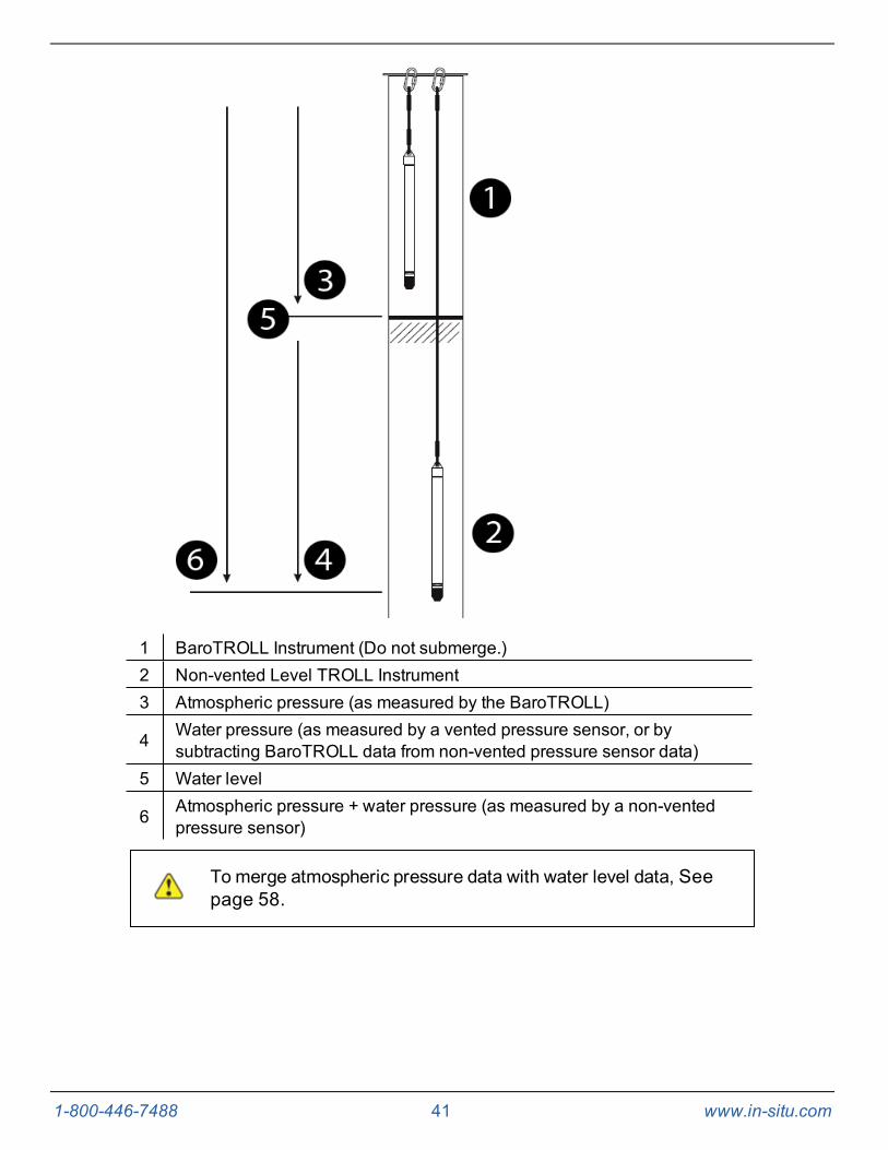
After the BaroTROLL Instrument is programmed, install it in a protected location abovethe water level near the submerged water level instrument. One installationconfiguration option is shown below using a twist-lock hanger and a suspension wire.
To prevent flooding of the BaroTROLL electronics, attach thetwist-lock hanger before you install the BaroTROLL.
1-800-446-7488 41 www.in-situ.com
1 BaroTROLL Instrument (Do not submerge.)2 Non-vented Level TROLL Instrument3 Atmospheric pressure (as measured by the BaroTROLL)
4 Water pressure (as measured by a vented pressure sensor, or bysubtracting BaroTROLL data from non-vented pressure sensor data)
5 Water level
6 Atmospheric pressure + water pressure (as measured by a non-ventedpressure sensor)
To merge atmospheric pressure data with water level data, Seepage 58.

1-800-446-7488 42 www.in-situ.com
Software Overview
First Screen (Data Tab)When you open Win-Situ 5 Software, the Data tab appears. The left side of the screencontains a file tree where you can view previously downloaded site data as well as datayou have exported to Microsoft Office Excel. The link on the right side of the screenshows where downloaded data is stored on your computer. The open plug icon in thelower-right corner of the screen indicates that the software is not yet communicatingwith an instrument.
Screen Element Definition
The disconnected plug indicates the instrument is notcommunicating with the software. Click to establish communicationwith a connected instrument.
The connected plug indicates the instrument is communicatingwith the software. Click to disconnect the software from theinstrument.
The Home tab displays real-time readings from the instrument.When connection to the instrument is first established, the softwaredisplays one reading of all available parameters in light gray.You must click the Play button at the bottom of the screento view real-time readings.
1-800-446-7488 43 www.in-situ.com
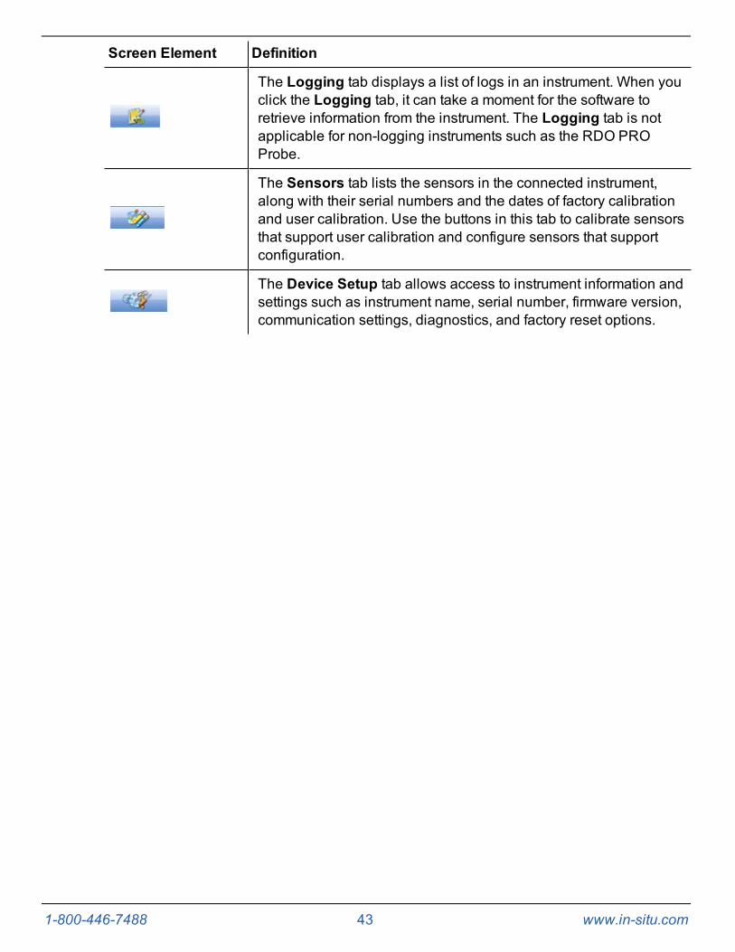
Screen Element Definition
The Logging tab displays a list of logs in an instrument. When youclick the Logging tab, it can take a moment for the software toretrieve information from the instrument. The Logging tab is notapplicable for non-logging instruments such as the RDO PROProbe.
The Sensors tab lists the sensors in the connected instrument,along with their serial numbers and the dates of factory calibrationand user calibration. Use the buttons in this tab to calibrate sensorsthat support user calibration and configure sensors that supportconfiguration.
The Device Setup tab allows access to instrument information andsettings such as instrument name, serial number, firmware version,communication settings, diagnostics, and factory reset options.

1-800-446-7488 44 www.in-situ.com
Home TabThe Home tab displays real-time readings from a connected instrument. When you firstestablish communication, the software displays one reading of all available parametersin light gray. You must click the Start button to view real-time readings.
Screen Element Definition
The Sites button allows you to add, edit, or delete a site. Click thedrop-down arrow next to the button to view the list of sites.
The Device Memory gauge turns yellow when the internal memoryis used. Note: Non-logging instruments do not have internalmemory, however, the gauge shows 100 percent green when poweris applied.
The Device Battery gauge turns yellow as the battery is depleted.This example shows 80 percent of the battery remaining (green) and20 percent used (yellow). Note: Non-logging instruments do nothave internal batteries, however, the gauge shows 100 percentgreen when power is applied.

1-800-446-7488 45 www.in-situ.com
Screen Element Definition
The Logging Status icon:
Green—The instrument is actively logging data.
Gray—The instrument has no logs pending or running. Non-logging instruments always show a gray status icon.
Yellow—The instrument has log data that was collectedaccording to specific instructions in the "Pending" or"Suspended" state.
The Alarm icon provides additional instrument statusinformation.
Green—No alarms or warnings
Yellow—One or more warnings
Red—One or more alarms
Move the cursor over the alarm icon to view a description.Click the Device Setup tab for detailed information on thealarm or warning.
Note: Disregard the Device Reset alarm for non-logginginstruments such as the RDO PRO Probe or the Aqua TROLL400.
System Time is displayed on the left. Device Time is displayed onthe right. Clocks are updated once every two seconds. When theDevice Time is displayed in red, it differs from the current SystemTime, and should be synchronized.
The Time Sync button is used to write the current PC time to theinstrument. If you need to set the instrument clock to a time otherthan the system (PC) time, use the Set Clock button on the DeviceSetup tab.
Meter View shows the last known parameter values, displayed withcurrent units and time stamp. Readings are sized to occupy theentire screen. This is the default display in the Home tab. If the typeis black, the readings are updating in real time.
List View is a running list of the most recent records. New readingsare continuously added to the top of the list and old readings scrolloff the bottom.
Graph View shows a real-time trend graph of the selectedparameters.
The Snapshot button records one set of readings.
1-800-446-7488 46 www.in-situ.com
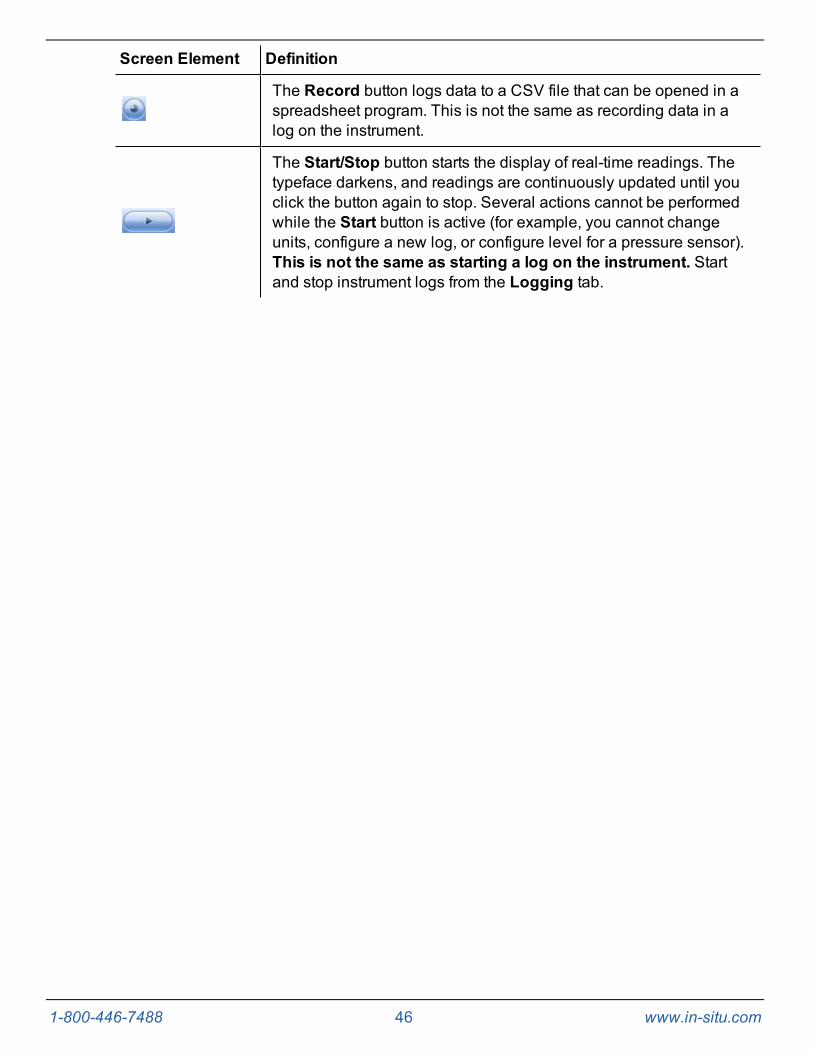
Screen Element Definition
The Record button logs data to a CSV file that can be opened in aspreadsheet program. This is not the same as recording data in alog on the instrument.
The Start/Stop button starts the display of real-time readings. Thetypeface darkens, and readings are continuously updated until youclick the button again to stop. Several actions cannot be performedwhile the Start button is active (for example, you cannot changeunits, configure a new log, or configure level for a pressure sensor).This is not the same as starting a log on the instrument. Startand stop instrument logs from the Logging tab.
1-800-446-7488 47 www.in-situ.com
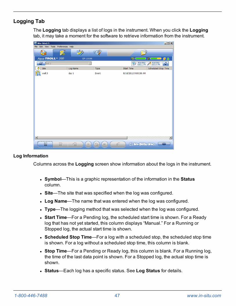
Logging TabThe Logging tab displays a list of logs in the instrument. When you click the Loggingtab, it may take a moment for the software to retrieve information from the instrument.
Log Information
Columns across the Logging screen show information about the logs in the instrument.
l Symbol—This is a graphic representation of the information in the Statuscolumn.
l Site—The site that was specified when the log was configured.
l Log Name—The name that was entered when the log was configured.
l Type—The logging method that was selected when the log was configured.
l Start Time—For a Pending log, the scheduled start time is shown. For a Readylog that has not yet started, this column displays “Manual.” For a Running orStopped log, the actual start time is shown.
l Scheduled Stop Time—For a log with a scheduled stop, the scheduled stop timeis shown. For a log without a scheduled stop time, this column is blank.
l Stop Time—For a Pending or Ready log, this column is blank. For a Running log,the time of the last data point is shown. For a Stopped log, the actual stop time isshown.
l Status—Each log has a specific status. See Log Status for details.

1-800-446-7488 48 www.in-situ.com
l Used Size—Kilobytes of instrument memory allocated for this log. For a Pendingor Ready log, the current size of the log configuration is shown. For a Completedlog, the size of the entire log file is shown. For a Running log, the current size ofthe log up to the last data point is shown.
Log Status
The status of each log in the instrument is displayed in the Logging tab by a symbolbeside the log name, and in the Status column.
l Ready—Manual Start log is ready to start.
l Pending—Scheduled start log is ready to start at its programmed time, or whenyou click the Start button.
l Running—The log is actively logging data.
l Suspended—The log has been paused (stopped temporarily).
l Stopped—The log has been stopped, either manually or on a schedule.
l Deleted—The log has been marked for deletion and will be deleted from theinstrument when memory is needed. The software manages this automatically.
l Invalid—The log as programmed cannot be run.
Ready, Pending, Running, and Suspended logs areconsidered active. Only one log can be active in the instrument.
Log Control Buttons
You can control the status of a log by selecting the log and clicking the appropriatebutton in the Logging tab control panel:
The Start button starts a Ready or Pending log, or resumes a Suspended log.
The Pause button pauses a Running log allowing you the option to resume it.
The Restart button restarts the selected Running log from the beginning. This canbe useful during aquifer testing using a logarithmic data collection schedule.
The Stop button permanently stops the selected Running log.
Log Operations
Use the buttons in the control panel to perform the following actions:
Create a new log.
The New button is disabled if a Ready, Pending, Running, or Suspended log is on theinstrument. When the instrument contains its maximum number of logs, the New buttonis unavailable.
Edit (or review) the log configuration for a Ready, Pending, or Invalid log.
Delete the log. (Note that you must delete a log twice before it is permanentlyremoved.)
Download the log to a PC.
1-800-446-7488 49 www.in-situ.com
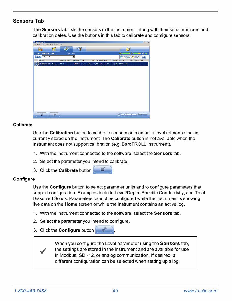
Sensors TabThe Sensors tab lists the sensors in the instrument, along with their serial numbers andcalibration dates. Use the buttons in this tab to calibrate and configure sensors.
Calibrate
Use the Calibration button to calibrate sensors or to adjust a level reference that iscurrently stored on the instrument. The Calibrate button is not available when theinstrument does not support calibration (e.g. BaroTROLL Instrument).
1. With the instrument connected to the software, select the Sensors tab.
2. Select the parameter you intend to calibrate.
3. Click the Calibrate button .
Configure
Use the Configure button to select parameter units and to configure parameters thatsupport configuration. Examples include Level/Depth, Specific Conductivity, and TotalDissolved Solids. Parameters cannot be configured while the instrument is showinglive data on the Home screen or while the instrument contains an active log.
1. With the instrument connected to the software, select the Sensors tab.
2. Select the parameter you intend to configure.
3. Click the Configure button .
When you configure the Level parameter using the Sensors tab,the settings are stored in the instrument and are available for usein Modbus, SDI-12, or analog communication. If desired, adifferent configuration can be selected when setting up a log.
1-800-446-7488 50 www.in-situ.com
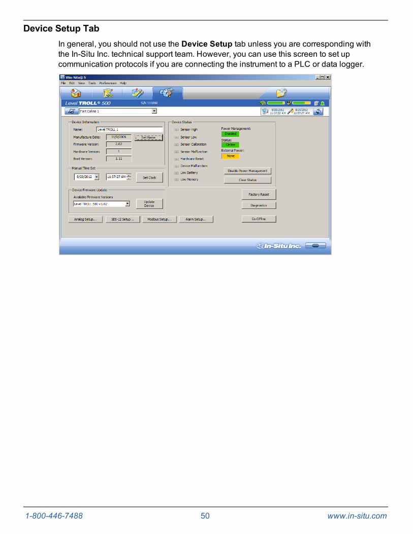
Device Setup TabIn general, you should not use the Device Setup tab unless you are corresponding withthe In-Situ Inc. technical support team. However, you can use this screen to set upcommunication protocols if you are connecting the instrument to a PLC or data logger.
1-800-446-7488 51 www.in-situ.com
Using Win-Situ 5 Software
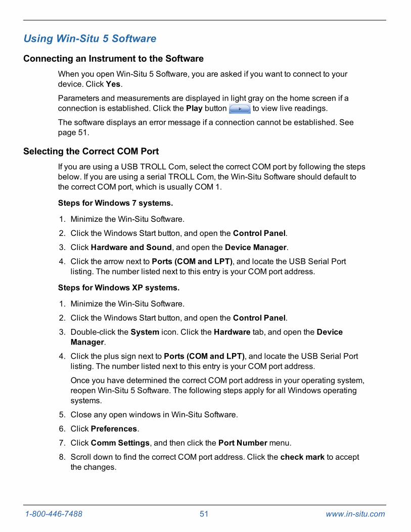
Connecting an Instrument to the SoftwareWhen you open Win-Situ 5 Software, you are asked if you want to connect to yourdevice. Click Yes.
Parameters and measurements are displayed in light gray on the home screen if aconnection is established. Click the Play button to view live readings.
The software displays an error message if a connection cannot be established. Seepage 51.
Selecting the Correct COM PortIf you are using a USB TROLL Com, select the correct COM port by following the stepsbelow. If you are using a serial TROLL Com, the Win-Situ Software should default tothe correct COM port, which is usually COM 1.
Steps for Windows 7 systems.
1. Minimize the Win-Situ Software.
2. Click the Windows Start button, and open the Control Panel.
3. Click Hardware and Sound, and open the Device Manager.
4. Click the arrow next to Ports (COM and LPT), and locate the USB Serial Portlisting. The number listed next to this entry is your COM port address.
Steps for Windows XP systems.
1. Minimize the Win-Situ Software.
2. Click the Windows Start button, and open the Control Panel.
3. Double-click the System icon. Click the Hardware tab, and open the DeviceManager.
4. Click the plus sign next to Ports (COM and LPT), and locate the USB Serial Portlisting. The number listed next to this entry is your COM port address.
Once you have determined the correct COM port address in your operating system,reopen Win-Situ 5 Software. The following steps apply for all Windows operatingsystems.
5. Close any open windows in Win-Situ Software.
6. Click Preferences.
7. Click Comm Settings, and then click the Port Numbermenu.
8. Scroll down to find the correct COM port address. Click the check mark to acceptthe changes.

1-800-446-7488 52 www.in-situ.com
9. Click the yellow Connect button in the lower right corner to establish a connectionto the instrument.
Setting the Instrument TimeThe instrument time and the current PC time are shown at the top of the screen whenan instrument is connected to the software.
The PC time appears on the left, the instrument time on the right. Both clocks areupdated at 0.5 Hz (once every two seconds). The device time is displayed in red if itdiffers by more than a few seconds from the current PC time. Data logging schedulesdepend on a correct instrument time.
To synchronize the instrument time to the current PC time, click the Clock Sync button. Win-Situ writes the current PC time to the instrument.
Adding a New SiteTo add a new site to the site database in your working directory do one of the following:
On the Data tab, click the Site Data folder, select File> New > Site.
or
On the Home tab, click the Site button to display the site list, then click New . Enter aname for the site. This is the only required field.
Click Save to save the new site. The new site will appear in the Site Data folder, andWin-Situ will add it to the site database in the working directory on your computer. It isnow available to select for any instrument log.
Log SetupThe Log Setup Wizard presents sequential screens to help you supply all theinformation necessary to set up a data log in the instrument.
To access the Log Setup Wizard the instrument must be connected to the software.
1. Click the Logging tab .
2. Click the New button .
The New button may be disabled or may show a warning if anactive log already exists on the instrument, or if the instrument ispolling live data (see the Home screen), or if the device alreadycontains its maximum number of logs.
3. Select the Site where the set of data will be logged and supply a name for the log.
4. Click the right arrow to continue after each step.

1-800-446-7488 53 www.in-situ.com
5. Select the parameters you intend to measure, choose the measurement units, andspecify the order in which the selected parameters will be logged.
6. Select the logging method you intend to use. See page 53.
7. Select the log interval. A log interval is how often a measurement will be taken andstored.
8. Select the start condition, stop condition, and specify how to handle full devicememory.
9. If you selected Level or Depth as a parameter to measure, specify how you intendto log this parameter. See page 54.
10. The final screen summarizes the log setup. Click the check mark to write thisinformation to the instrument.
Logging Method DescriptionsThe following is a list of log types and their descriptions. The log types that areavailable on an instrument vary depending upon the capabilities of the instrumentmodel.
Logging Methods for Long-Term Monitoring
Linear
Linear log type measures and records at a user-defined fixed interval of one minute ormore. This method is used for long-term studies, landfill monitoring, stream gauging,tidal studies, and background monitoring prior to aquifer testing. Intervals are measuredin days, hours, or minutes.
Linear Average
Linear Average log type can smooth out anomalous highs and lows that may occur in adata set, for example, when a water wave passes over the instrument. Each storedmeasurement is the average of several rapid measurements. This method is used forlong-term studies, stream gauging, tidal and open-water studies where trends are moreimportant than accuracy. Intervals are measured in days, hours, minutes, or seconds.
Event
Linear Event log type combines basic fixed-interval logging of specified parameterswith the ability to log data at a faster interval when a single-parameter event condition ispresent.
Logging Methods for Aquifer Testing
True Logarithmic
True Logarithmic log type captures early-time water-level data during aquifer testing.Measurements are very closely spaced at the start of the test (4 measurements persecond) and move further apart on a logarithmically decaying schedule as the test

1-800-446-7488 54 www.in-situ.com
progresses. There are 40 measurements per log decade. This log type is commonlyused for rapid step-drawdown pump tests, constant-rate pump tests, and slug tests.
Fast Linear
Fast Linear log type measures and records at a user-defined fixed interval of oneminute or less. The interval is small (seconds, milliseconds), and the test is usually ofshort duration due to the volume of data logged and the impact of very fast sampling onbattery life.
Step Linear
Step Linear log type measures and records data according to a number of user-definedelapsed time intervals or "steps" within a schedule. Both the elapsed time and thenumber of measurements within each step can vary. After completing the elapsed timefor each step, the schedule will automatically move to the next step. Up to 10 separatesteps can be defined.
About the Level ReferenceA Level Reference, also called an offset, is a user-specified starting point for loggedLevel readings. It is entered in the Logging Setup Wizard when a log is configured, or itcan be stored in the device without configuring a log using the Configure button in theSensors tab.
Depth mode does not require that you enter a Level Reference.
The Level Reference can be any value you choose. Here are some examples:
l Elevation—If you calculate the water level above mean sea level (MSL) and enterthis as the Level Reference, then elevations above MSL will be logged.
l Depth to Water—If you measure the depth to the water surface (DTW) from thetop of the well casing and enter this as the Level Reference, then DTW (alsocalled drawdown) values will be logged.
l Gauge Height or Stage—Logged readings track water level as related tomarkings on a nearby staff gauge.
l Zero—A Level Reference of 0 effectively sets the probe to zero at the start of thelog. Changes, both positive and negative, from the starting water level, will belogged.
Once you have determined the value of your Level Reference, the software gives youthree options for entering it. These control when the level reference is applied.
l New Reference—This option is designed to be used with an active softwareconnection when the device is installed in the water.
1-800-446-7488 55 www.in-situ.com
A new level reference must be entered while thedevice's pressure sensor is submerged in its finalposition in the water. This is because the current probereading is set equal to the Level Reference to create the offsetthat takes effect at the start of the data log. The log header willshow the probe reading at the time you entered the LevelReference.
During log setup, the software presents two additional options for entering the LevelReference:
l Set first logged reading—Use this option when the instrument will be deployedon wire rather than cable because you will not be able to communicate with theinstrument when it is submerged.
l Remind me to set reference later—Use this option to defer the entry of the LevelReference during log setup and set a reminder to enter it when the device issubmerged in its final position.
Starting a LogEvery log is programmed for either a manual or a scheduled start. A log with a manualstart time is displayed in the Logging screen with Ready in the Status column. A logwith a scheduled start time is displayed with Pending in the Status column.
Starting a Pending Log
A Pending log automatically starts at the scheduled time without any user intervention.
A scheduled log with Pending status can be manually started atany time before its scheduled start.
Starting a Manual Log
With the instrument connected to the software, select the Logging tab.
Select the Ready log you want to start.
Click the Start Log button . The log starts and the symbol changes. The Statuscolumn displays Running.
Suspending (Pausing) a LogA running log may be temporarily paused. For example, you might want to reposition aninstrument, calibrate a sensor, or clean a sensor and later resume the log. A log can besuspended and resumed three times.
1. With the instrument connected to the software, select the Logging tab .
2. Select the log you intend to suspend.
1-800-446-7488 56 www.in-situ.com
3. Click the Suspend button . Suspended appears in the Status column.
Resuming a Suspended Log
1. To resume logging after a log has been suspended, select the Logging tab.
2. Select the Suspended log.
3. Click the Start Log button . Logging resumes. Running appears in the Statuscolumn. The data file will show the time when the log was suspended and the timewhen it restarted.
Stopping a LogA log can be manually stopped at any time, even if a stop time has been previouslyscheduled. If you did not specify a stop condition when you defined the log, the log willrun until the instrument is out of memory or battery power, or until you manually stop it.
A log that has been stopped cannot be resumed. If you intend toresume a log later, you should suspend a log rather than stop it.
1. To manually stop a log, the instrument must be connected to the software.
2. Select the Logging tab .
3. Select the running log you intend to stop.
4. Click the Stop Log button .
Downloading Data to a PCThis procedure copies the data log from the instrument to a PC. It does not remove thedata log from the instrument. After a log is downloaded, it can be exported to a CSV fileformat that can be used by spreadsheet programs. The time shown in the log name isthe time the log was downloaded.
1. With an instrument connected, select the Logging tab .
2. Select the log you intend to download.
3. Choose a Running, Suspended, Stopped, or Deleted log.
4. Click the Download button.
5. In the next screen, select one of the three download options.
l All data
l New data (data logged since the last download)
l Time interval to download
1-800-446-7488 57 www.in-situ.com
New data is downloaded by default to a new log file. To appendnew data to the last download of this log, be sure the option"Append logs on download" is selected in the General Settingsdialog (Preferences >General Settings).
2. The log is copied to the connected PC into your Win-Situ working directory folder.View or change the working directory using File > Settings.
3. At the end of the download, Win-Situ gives you the option of viewing the data.
l Select Yes and the log is displayed in the Data screen.
l Select No and the Logging screen appears. You can view the dataat any time by selecting it in the Data tab.
Viewing Logged Data
1. To view the data stored in the instrument, you must first download the data. Aconnection to an instrument is not needed after the data log has been downloaded.
2. Select the Data tab .
3. On the left side of the screen, select the log you want to view. To expand a foldershown in the navigation tree, double-click the folder. The content of the data log isdisplayed on the right side of the screen in text or graph format.
To switch between view formats, click the Text or theGraphbutton in the control panel. To customize the text or graph view,select Preferences > Graph Settings or Preferences >Data View Settings. These options apply to all downloads untilyou change them.
1-800-446-7488 58 www.in-situ.com
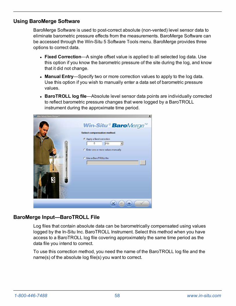
Using BaroMerge SoftwareBaroMerge Software is used to post-correct absolute (non-vented) level sensor data toeliminate barometric pressure effects from the measurements. BaroMerge Software canbe accessed through the Win-Situ 5 Software Tools menu. BaroMerge provides threeoptions to correct data.
l Fixed Correction—A single offset value is applied to all selected log data. Usethis option if you know the barometric pressure of the site during the log, and knowthat it did not change.
l Manual Entry—Specify two or more correction values to apply to the log data.Use this option if you wish to manually enter a data set of barometric pressurevalues.
l BaroTROLL log file—Absolute level sensor data points are individually correctedto reflect barometric pressure changes that were logged by a BaroTROLLinstrument during the approximate time period.
BaroMerge Input—BaroTROLL FileLog files that contain absolute data can be barometrically compensated using valueslogged by the In-Situ Inc. BaroTROLL Instrument. Select this method when you haveaccess to a BaroTROLL log file covering approximately the same time period as thedata file you intend to correct.
To use this correction method, you need the name of the BaroTROLL log file and thename(s) of the absolute log file(s) you want to correct.

1-800-446-7488 59 www.in-situ.com
1. From the Tools menu in Win-Situ 5 Software, selectWin-Situ BaroMerge.
2. Select the "Use a BaroTROLL file:" option.
3. Click the browse button to the right of the file field.
4. Select a BaroTROLL file and click the check mark.
5. Values from the BaroTROLL file will be displayed in the next window. You can editthese values if necessary.
6. Click the right arrow button.
7. Select the log file(s) you intend to correct and click the check mark.
8. Compensated data files can be viewed or exported from the Data tab.
BaroMerge OutputYour original log file is not changed. A new, corrected log file with the same name andpath is created. The original “.wsl” extension is replaced by “-Baro Merge.wsl”.
1-800-446-7488 60 www.in-situ.com
Disconnecting an Instrument From the SoftwareClick the plug icon in the lower-right corner of the screen to disconnect theinstrument from the software.
Disconnect the instrument from the TROLL Com Communication Device. Attach adesiccant pack if you are using a vented cable.
Connect to a Data Logger or PLC ControllerThe instrument can be connected to a data logger or controller via a stripped-and-tinned RuggedCable System for communication using one of the following protocols.
l Analog (4-20 mA)
l SDI-12
l RS485 Modbus
l RS232 Modbus (with a customer-supplied converter)
Stripped-and-tinned RuggedCable System includes a female connector on one endthat connects to the instrument. The uphole end terminates in stripped-and-tinned wiresfor connection to a PLC controller or data logger.
A shorter length Stripped-and-tinned RuggedCable System with a male connector isavailable to convert a female to female RuggedCable System to a stripped-and-tinnedconfiguration.

1-800-446-7488 61 www.in-situ.com
1 PLC or Data Logger2 Stripped-and-tinned RuggedCable System with female connector3 Short stripped-and-tinned RuggedCable System with male connector4 RuggedCable System with female to female twist-lock connector5 Instrument

1-800-446-7488 62 www.in-situ.com
WiringRefer to the diagrams on the following pages for wiring information. Make sure that youtrim and insulate unused wires. The shield must be wired to a chassis ground or earthground.
Signal Color Pin
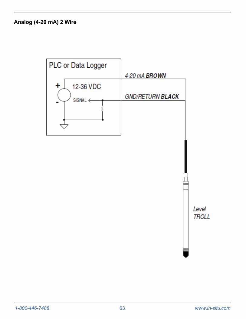
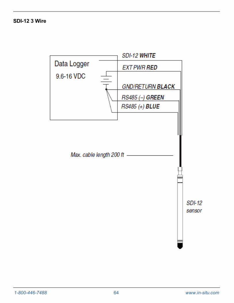
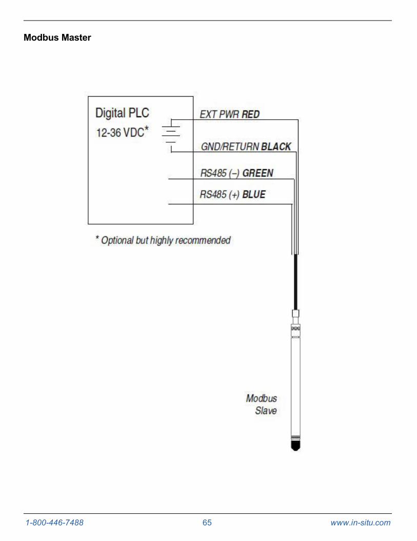
Gnd/Return Black 6
Ext Power Red 5
4-20 mA Brown 4
RS485(-) Green 3
RS485(+) Blue 2
SDI-12 White 1
1-800-446-7488 63 www.in-situ.com
Analog (4-20 mA) 2 Wire
1-800-446-7488 64 www.in-situ.com
SDI-12 3 Wire
1-800-446-7488 65 www.in-situ.com
Modbus Master

1-800-446-7488 66 www.in-situ.com
Modbus Master with RS232 (Converter Required)
1-800-446-7488 67 www.in-situ.com
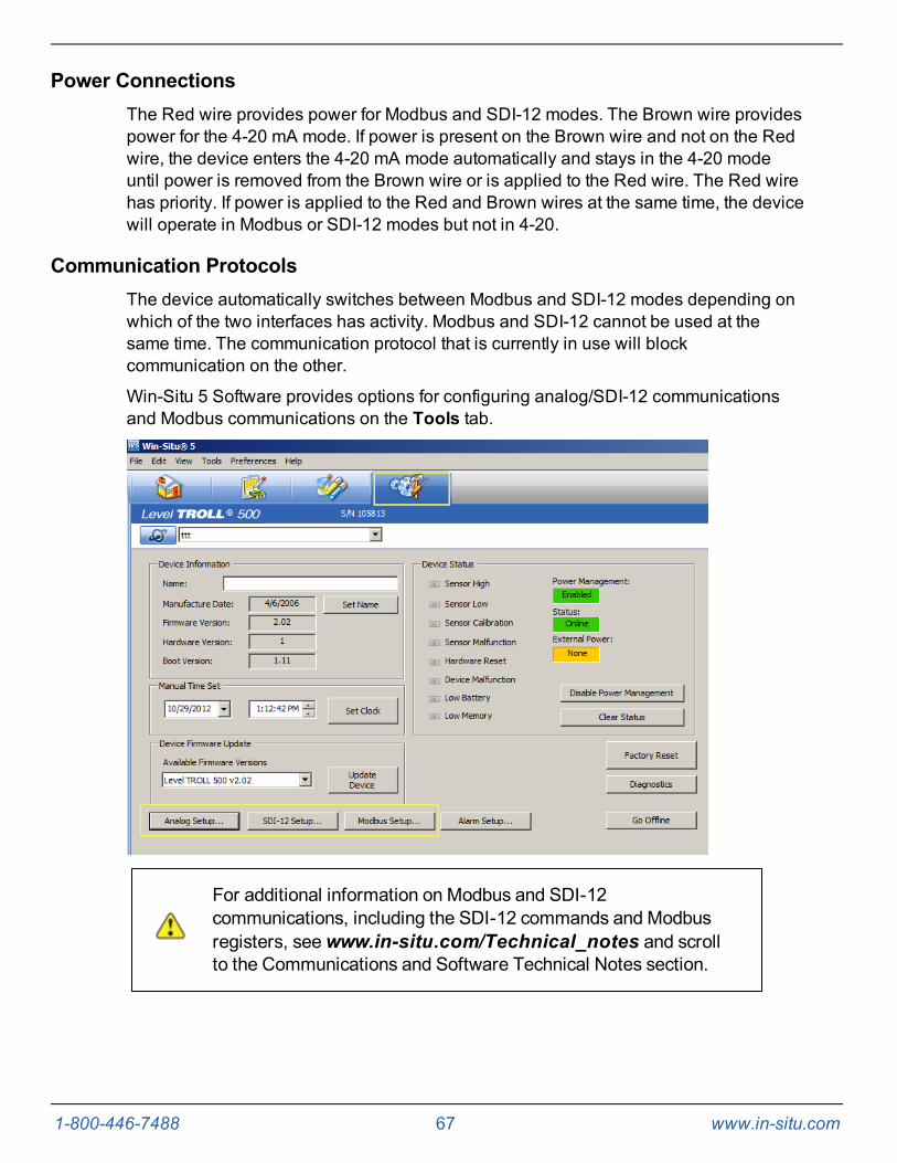
Power ConnectionsThe Red wire provides power for Modbus and SDI-12 modes. The Brown wire providespower for the 4-20 mA mode. If power is present on the Brown wire and not on the Redwire, the device enters the 4-20 mA mode automatically and stays in the 4-20 modeuntil power is removed from the Brown wire or is applied to the Red wire. The Red wirehas priority. If power is applied to the Red and Brown wires at the same time, the devicewill operate in Modbus or SDI-12 modes but not in 4-20.
Communication ProtocolsThe device automatically switches between Modbus and SDI-12 modes depending onwhich of the two interfaces has activity. Modbus and SDI-12 cannot be used at thesame time. The communication protocol that is currently in use will blockcommunication on the other.
Win-Situ 5 Software provides options for configuring analog/SDI-12 communicationsand Modbus communications on the Tools tab.
For additional information on Modbus and SDI-12communications, including the SDI-12 commands and Modbusregisters, seewww.in-situ.com/Technical_notes and scrollto the Communications and Software Technical Notes section.

1-800-446-7488 68 www.in-situ.com
Redundant LoggingThe instrument is capable of internal logging while participating in a Modbus, SDI-12 oranalog network. However, Win-Situ 5 Software cannot communicate with theinstrument while it is transmitting Modbus, SDI-12, or 4-20 mA analog data, and theinstrument cannot receive or respond to Modbus, SDI-12, or 4-20 mA analogcommands while connected to a PC serial port.
If the PLC or data logger loses data, the data that was logged internally on theinstrument can be retrieved using Win-Situ 5 Software.
If the PLC or data logger experiences power loss, the instrument will continue to collectdata using its internal batteries and clock.
A port-powered RS485 converter like that shown for Modbus connections may be usedfor temporary connection of the Level TROLL to a serial port on a PC.
1-800-446-7488 69 www.in-situ.com
Cleaning and Maintenance
OverviewIt is important for users to perform scheduled maintenance on their instruments tosustain the accuracy and longevity of the probes and cables. The frequency of thismaintenance depends on the characteristics of the deployment site, including humiditylevels and the degree of fouling.
Users should be aware of the conditions at their deployment sites and developappropriate maintenance schedules to replace desiccant, clean the instruments, andsend in the instruments for factory calibration. Users should check instruments oftenduring the first portion of the deployment to determine the frequency of maintenance.General maintenance should be performed as often as possible. In-Situ Inc.recommends that you send your instrument in for factory service at least every 12months.
Operating ConsiderationsThe instrument has been designed to withstand harsh field conditions. However, aswith any electronic instrument, it can be permanently damaged if used outside itsoperating specifications.
Temperature
Review the instrument specifications to determine the operating range. Do not deployinstruments in such a way that ice may form on or near the sensors or cableconnections. Ice formation is a powerful expansive force that can over-pressurize thesensor or otherwise cause damage that is not covered by the warranty.
Pressure Range
The instrument can withstand pressures of up to two times (2X) the rated range of thepressure sensor without damage, although it may not read correctly at such pressure. Ifthe pressure range is exceeded by 3X, the sensor will be destroyed.
Batteries
Internal batteries in the instrument are not user-replaceable. The approximatepercentage remaining is displayed on the Win-Situ 5 Dashboard when the instrument isconnected in software.
If batteries are completely exhausted, external power and battery pack options areavailable. See page 23.
1-800-446-7488 70 www.in-situ.com
Desiccant Pack Options
Small Desiccant
The Small Desiccant is a disposable cap that ships with In-Situ Inc. products. The smalldesiccant is meant to protect the instrument and cable only during shipping andshould not be used for deployments.
Large Desiccant
The Large Desiccant is a replaceable desiccant pack designed for low-humidityenvironments or deployments where maintenance occurs frequently. The largedesiccant is available with a plastic or a titanium twist-lock connector.
Description Part Number
Large Desiccant, TitaniumLarge Desiccant, ABS
00518100053550
Outboard Desiccant
The Outboard Desiccant is a replaceable desiccant pack designed to attach to the venttube of the stripped-and-tinned cable.
Description Part Number
Outboard Desiccant 0051380
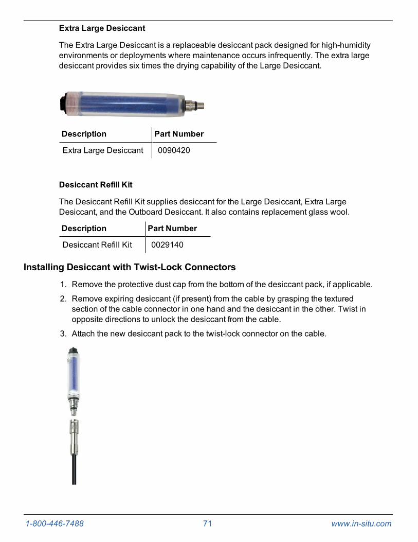
1-800-446-7488 71 www.in-situ.com
Extra Large Desiccant
The Extra Large Desiccant is a replaceable desiccant pack designed for high-humidityenvironments or deployments where maintenance occurs infrequently. The extra largedesiccant provides six times the drying capability of the Large Desiccant.
Description Part Number
Extra Large Desiccant 0090420
Desiccant Refill Kit
The Desiccant Refill Kit supplies desiccant for the Large Desiccant, Extra LargeDesiccant, and the Outboard Desiccant. It also contains replacement glass wool.
Description Part Number
Desiccant Refill Kit 0029140
Installing Desiccant with Twist-Lock Connectors
1. Remove the protective dust cap from the bottom of the desiccant pack, if applicable.
2. Remove expiring desiccant (if present) from the cable by grasping the texturedsection of the cable connector in one hand and the desiccant in the other. Twist inopposite directions to unlock the desiccant from the cable.
3. Attach the new desiccant pack to the twist-lock connector on the cable.

1-800-446-7488 72 www.in-situ.com
Installing Outboard DesiccantVented cable must be installed with outboard desiccant to protect the cable andinstrument electronics from condensation in high-humidity environments.
The desiccant can be removed from the vent tube, if necessary, to trim the conductorwires. However, you must reinstall the desiccant after trimming and connecting thewires.
1. Cut off the knot at the bottom of the vent tube extension.
2. Firmly attach the vent tube extension to the cable vent tube. Cover at least 6.4 mm(0.25 in.) of the cable vent tube for a secure attachment.
3. Use the attached hook-and-loop strap to secure the desiccant to the cable, belowthe stripped wires.
4. Remove the red dust cap from the black nylon cap to allow air to reach the cable’svent tube.
1 Outboard desiccant is attached to thecable vent tube.
2 Desiccant is secured to the cable with astrap.
Using the Desiccant Refill Kit
1. Remove the black nylon vent cap from the top of the desiccant.
2. Pour out and discard the used desiccant. Check the glass wool in the bottom of thecontainer and replace if necessary.
The glass wool prevents the desiccant beads from falling out thecable end of the desiccant pack. If the wool glass does thiseffectively, there is no need to replace it when refilling thedesiccant.

1-800-446-7488 73 www.in-situ.com
3. Fill the container with fresh desiccant. Replace the vent cap. Reattach to cable ifremoved.
Antifouling
TROLL Shield Nose Cone
The copper TROLL Shield Nose Cone is designed to reduce macro- and micro-foulingof the pressure sensor on Level TROLL and Aqua TROLL Instruments. Reducedfouling on the sensor improves measurement accuracy and extends the length ofdeployments.
For optimum performance, the TROLL Shield Nose Cone should be replaced every 12months or sooner if site conditions are extremely harsh.
Description Part Number
TROLL Shield Nose Cone 0081480
O-ring Inspection and ReplacementExamine O-rings for wear, dryness, discoloration, stretching, cracks, nicks, andbrittleness. Replace when any of these conditions are present. Replacing O-rings on aregular schedule, regardless of O-ring condition, is the best way to protect againstdamage.
Perform the following steps to replace an O-ring.
1. Remove and discard the damaged O-ring.
2. Use a clean, dry, soft cloth to clean the O-ring groove to remove dirt or residue.
3. Lubricate the new O-ring using high-vacuum grease.
a. Wash your hands thoroughly.
b. Apply a small amount of grease to the pad of your index finger, andrub your index finger and thumb together to spread the greaseevenly.
c. Inspect the new O-ring and remove any debris stuck to it.
d. Rub your fingers around the O-ring until there is a thin layer ofgrease on the entire O-ring.
4. Install the O-ring in the groove and remove any excess lubricant with a clean cloth.
Do not allow water or lubricant to enter the connector.

1-800-446-7488 74 www.in-situ.com
Cleaning and Storage
Cleaning the Instrument
Clean the instrument body with water and a soft brush or plastic scouring pad, or soakovernight in a mild acidic solution, such as household vinegar. NEVER submerge thetwist-lock connector portion of the instrument when it is not connected to a cable.
If the ports on the front end are clogged with silt or mud, try the following procedures.
l Agitate the instrument vigorously in a bucket of clean water.
l Apply a gentle rinse of water from a wash bottle.
l In severe cases, remove the nose cone and clean out the holes with a soft brushor pipe cleaner.
Do not attempt to remove material from the instrument by tapping the instrument againsta surface. To avoid damage to the pressure sensor diaphragm, do not insert any objectinto the sensor opening or attempt to dig out dirt or other materials. You void theinstrument's warranty by inserting anything into the sensor opening. Ifcontamination cannot be removed using the recommendations above, please contactIn-Situ Inc. for cleaning.
A TROLL pressure sensor with the nose cone removed. Do not insert ANY object intothe sensor opening. Doing so voids the warranty.
Twist-Lock Connectors
Keep the pins on all connectors free of dirt and moisture by using the soft protectivedust caps when cable is not attached.
Storage
Store the instrument in a clean, dry place. Place the protective red dust cap on thecable end or store with cable attached to protect the connector pins and O-ring. Ensuredesiccant is the appropriate size and change it when needed. Store the instrumentwhere it will not roll off a bench onto a hard surface or sustain other mechanical shock.Protect the instrument from temperature extremes. Store instruments properly:
l Level TROLL Instruments—store within the temperature range -40° C to +80° C (-40° F to +176° F)
1-800-446-7488 75 www.in-situ.com
Factory Calibration and Service
In-House Factory Calibration
Factory calibration of In-Situ Inc. instruments should be performed every 12 months, orwhen the unit data appears to drift significantly. Factory calibration includes a thoroughcleaning, full functionality check, and adjustments of the pressure sensor, temperaturesensor, and conductivity sensor (when applicable) over the entire calibratedtemperature range.
Return Materials Authorization (RMA) Form
To obtain a factory calibration, fill out and return the online Return MaterialsAuthorization (RMA) form located at www.in-situ.com/Return_authorization.
Obtaining Repair Service
If you suspect your system is malfunctioning and repair is needed, you can help assureefficient servicing by following these guidelines:
1. Call or email In-Situ Technical Support. Have the product model and serial numberavailable.
2. Be prepared to describe the problem, including how the product was used and theconditions noted at the time of the malfunction.
3. If Technical Support determines that service is needed, they will ask that yourcompany to fill out the RMA form and pre-approve a specified monetary amount forrepair charges. When the form and pre-approval is received, Technical Support willassign an RMA (Return Material Authorization) number.
4. Clean the product as described in the manual.
5. If the product contains a removable battery, remove and retain it unless you arereturning the system for a refund or Technical Support states otherwise.
6. Carefully pack your product in its original shipping box, if possible.
7. Mark the RMA number clearly on the outside of the box.
8. Send the package, shipping prepaid, to:
In-Situ Inc.ATTN: Repairs221 East Lincoln AvenueFort Collins, CO 80524
The warranty does not cover damage during transit. In-Situ recommends insurance forall shipments. Warranty repairs will be shipped back prepaid.
Outside the U.S.
Contact your international In-Situ distributor for repair and service information.

1-800-446-7488 76 www.in-situ.com
Guidelines for Cleaning Returned Equipment
Please help us protect the health and safety of our employees by cleaning anddecontaminating equipment that has been subjected to potential biological or healthhazards, and labeling such equipment. Unfortunately, we cannot service yourequipment without such notification. Please complete and sign the form on page 77 (ora similar statement certifying that the equipment has been cleaned anddecontaminated) and send it to us with each instrument.
l We recommend the glassware cleaning product, Alconox, available from In-Situand from laboratory supply companies.
l Clean all cables and remove all foreign matter.
l Clean the cable connectors with a clean, dry cloth. Do not submerge theconnectors.
l Clean the instrument including the nosecone, cable head, and protective caps.
If an instrument is returned to our Service Center for repair orrecalibration without a statement that it has been cleaned anddecontaminated, or if it is the opinion of our ServiceRepresentatives that the equipment presents a potential health orbiological hazard, we reserve the right to withhold service untilproper certification is obtained.

1-800-446-7488 77 www.in-situ.com
Decontamination and Cleaning Form

1-800-446-7488 78 www.in-situ.com
TroubleshootingIn addition to the following troubleshooting items, the In-Situ Inc. website includesinstructional videos, technical notes, and more. See www.in-situ.com/resources.Problem Possible Cause Possible Solution
Win-Situ 5 Software cannotconnect to the instrument.
Wrong COM port is selected,communication settings are incompatible,cable connections are loose or dirty, orbatteries are low.
Make sure cable connections are tight andconnectors are clean and dry.
Make sure the cable is securely attached to theinstrument.
Make sure the correct COM port is selected (selectPreferences > Comm Settings to verify).
Make sure the communication settings in Win-Situand in the instrument match. To reset the devicecommunication settings to the serial defaults, click“Reset all Devices” in the Comm Settings dialog(Preferences > Comm Settings).
Make sure the internal battery has voltageremaining, or external power is supplied.
See www.in-situ.com/Technical_notes and scrollto the Communications and Software TechnicalNotes section for more information.
Real-time readings display thewrong units. Default units are being used.
Click the Sensors tab, select the sensor, click theconfigure button and select the desired units foreach parameter in the Sensor Setup window.
Cannot add a new log.
Only one active log can reside in thedevice at a time—an active log is a logthat is Ready, Pending, Running, orSuspended as shown in the Statuscolumn of the Logging Tab.
The device has its maximum number oflogs already stored—the Level TROLL300, 500, and Baro TROLL have acapacity of 2 logs.
Stop or delete the log if possible. Alternatively,configure the new log after the active log iscompleted.
Download, and then delete a log you no longerneed. This will make room for an additional log onthe device.
New log exceeds availablememory (software message).
The log as configured would exceed thedevice memory.
Edit the log and select a longer sampling interval.
If available, select the "wrap data" option. Thiscauses more recent data to overwrite older datawhen memory is full.
For a log with a scheduled start, select None as thestop condition, or select a stop time that is closer tothe start time.
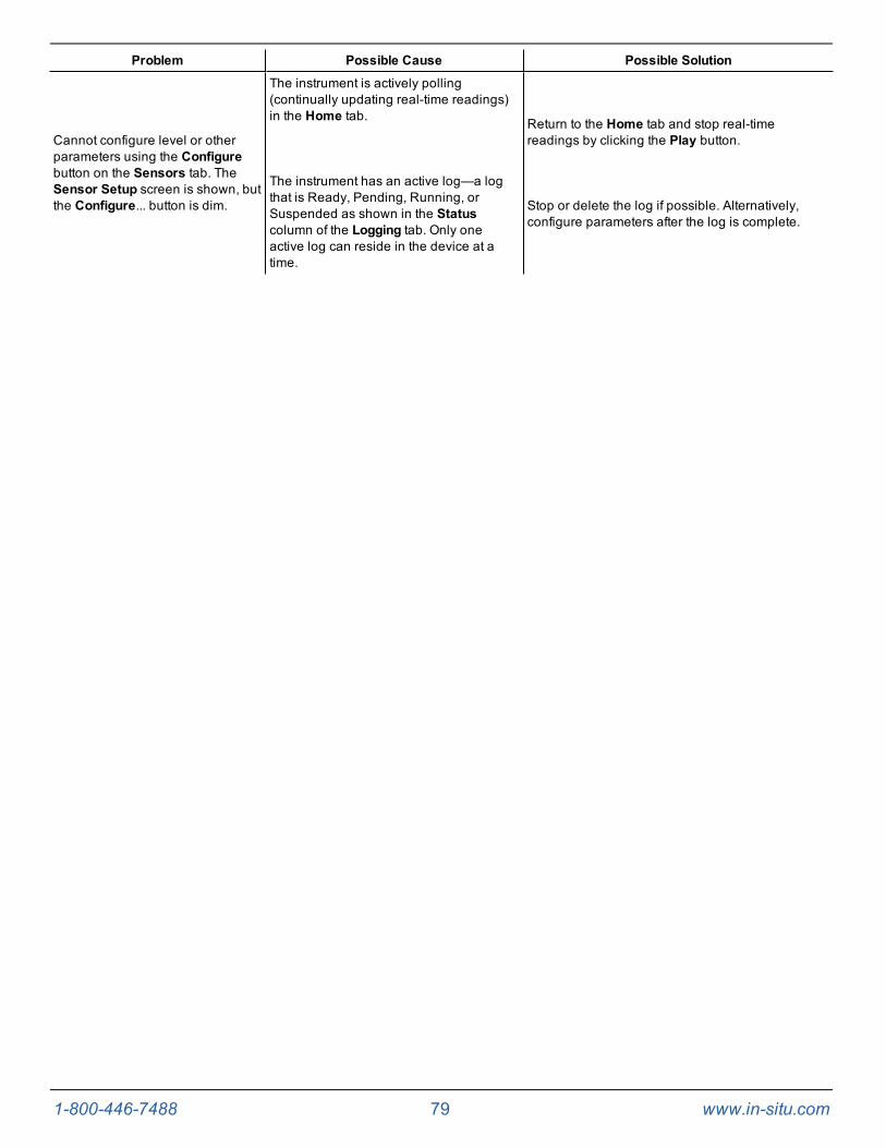
1-800-446-7488 79 www.in-situ.com
Problem Possible Cause Possible Solution
Cannot configure level or otherparameters using the Configurebutton on the Sensors tab. TheSensor Setup screen is shown, butthe Configure... button is dim.
The instrument is actively polling(continually updating real-time readings)in the Home tab.
The instrument has an active log—a logthat is Ready, Pending, Running, orSuspended as shown in the Statuscolumn of the Logging tab. Only oneactive log can reside in the device at atime.
Return to the Home tab and stop real-timereadings by clicking the Play button.
Stop or delete the log if possible. Alternatively,configure parameters after the log is complete.

1-800-446-7488 80 www.in-situ.com
Declaration of Conformity
Level TROLL 300 Instrument

1-800-446-7488 81 www.in-situ.com
Level TROLL 500 Instrument

1-800-446-7488 82 www.in-situ.com
Level TROLL 700 Instrument
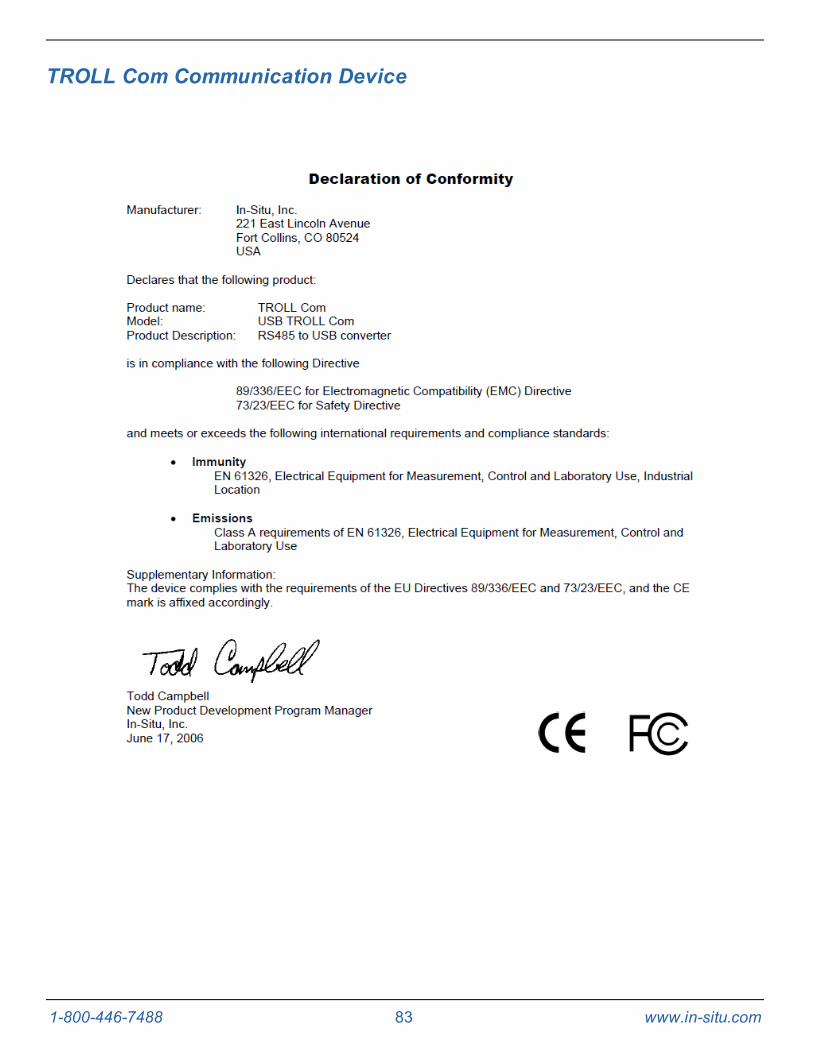
1-800-446-7488 83 www.in-situ.com
TROLL Com Communication Device
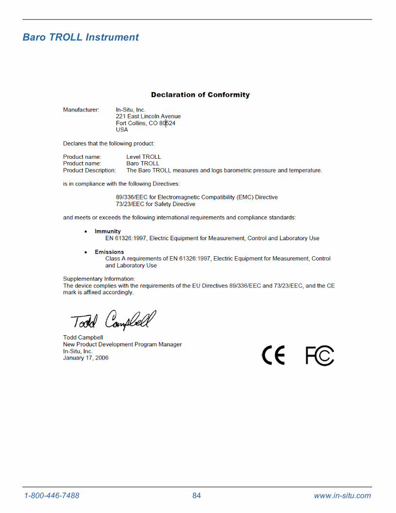
1-800-446-7488 84 www.in-situ.com
Baro TROLL Instrument