Letter of Transmittal - KIER Construction - "Experience ... · Letter of Transmittal To: ... KIER...
35
Ph : (801)627-1414 3710 QUINCY AVENUE OGDEN, UT 84403-1934 Date: 5/17/2012 Job: 12-78-00 CALIFORNIA SQUARE Letter of Transmittal Transmittal #: 16 To: WESTERN REGION NONPROFIT ATTN: GARY CARTER 223 WEST 700 SOUTH, SUITE 250 SALT LAKE CITY, UT 84101 Ph: (801)531-9200 Fax: (801)531-9201 Subject: Submittal Samples Change order Shop drawings Under separate cover via the following items: Attached WE ARE SENDING YOU Submittal Prints Plans Copy of letter Specifications Description No. Date Copies Document Type 1 5/17/12 15400-15500-001 Rev HVAC Submittal Other PRINTS RETURNED AFTER LOAN TO US FOR BIDS DUE For review and comment Return ___ corrected prints Returned for corrections Submit ___ copies for distribution Approved as noted For approval Resubmit ___ copies for approval Approved as submitted THESE ARE TRANSMITTED as checked below: FOR YOUR APPROVAL. THANK YOU. Remarks: For your use As requested Copy To: Signature: From: BRIAN VAN GORP (KIER CONSTRUCTION CO If enclosures are not as noted, kindly notify us at once. Page 1 of 1
Transcript of Letter of Transmittal - KIER Construction - "Experience ... · Letter of Transmittal To: ... KIER...

Ph : (801)627-1414
3710 QUINCY AVENUEOGDEN, UT 84403-1934
Date: 5/17/2012Job: 12-78-00 CALIFORNIA SQUARE
Letter of Transmittal
Transmittal #: 16To: WESTERN REGION NONPROFITATTN: GARY CARTER223 WEST 700 SOUTH, SUITE 250SALT LAKE CITY, UT 84101Ph: (801)531-9200 Fax: (801)531-9201
Subject: Submittal
Samples
Change order
Shop drawings
Under separate cover via the following items:AttachedWE ARE SENDING YOU
Submittal
Prints Plans
Copy of letter Specifications
DescriptionNo.DateCopiesDocument Type
1 5/17/12 15400-15500-001 Rev
HVACSubmittal
Other
PRINTS RETURNED AFTER LOAN TO USFOR BIDS DUE
For review and comment
Return ___ corrected printsReturned for corrections
Submit ___ copies for distributionApproved as noted
For approval Resubmit ___ copies for approvalApproved as submitted
THESE ARE TRANSMITTED as checked below:
FOR YOUR APPROVAL.
THANK YOU.
Remarks:
For your use
As requested
Copy To:
Signature:From: BRIAN VAN GORP (KIER CONSTRUCTION CO
If enclosures are not as noted, kindly notify us at once. Page 1 of 1
brian
SIGNATURE

Ph : (801)627-1414
3710 QUINCY AVENUEOGDEN, UT 84403-1934
Job:
CALIFORNIA SQUARE
Package No:
1600 GARLAND AVENUE
Spec Section No:1540015500-001
Sent Date:Revision No: 0
Submittal
5/17/2012
12-78-00
LOUISVILLE, KY 40210 Spec Sections Included:
Spec Section Title: Plumbing
Submittal Title: HVAC
E & E MECHANICAL INC12-78-00
Sub/Supplier:
Contractor's Stamp
Architect's Stamp Engineer's Stamp
ROGER NIELSEN
KIER CONSTRUCTION CORPORATION
Contractor:
Owner:WESTERN REGION NONPROFIT HOUSI12-78-00
brian
REVIEW STAMP
brian
Rejected
brian
Reviewed
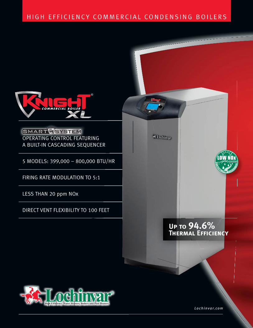
Up to 94.6%Thermal Efficiency
Lo c h i n v a r.c o m
H I G H E F F I C I E N C Y CO M M E R C I A L CO N D E N S I N G B O I L E R S
OPERATING CONTROL FEATURING A BUILT-IN CASCADING SEQUENCER
5 MODELS: 399,000 – 800,000 BTU/HR
FIRING RATE MODULATION TO 5:1
LESS THAN 20 ppm NOx
DIRECT VENT FLEXIBILITY TO 100 FEET
OPERATING CONTROL FEATU
brian
Text Box
2 BOILERS Model: KBN801
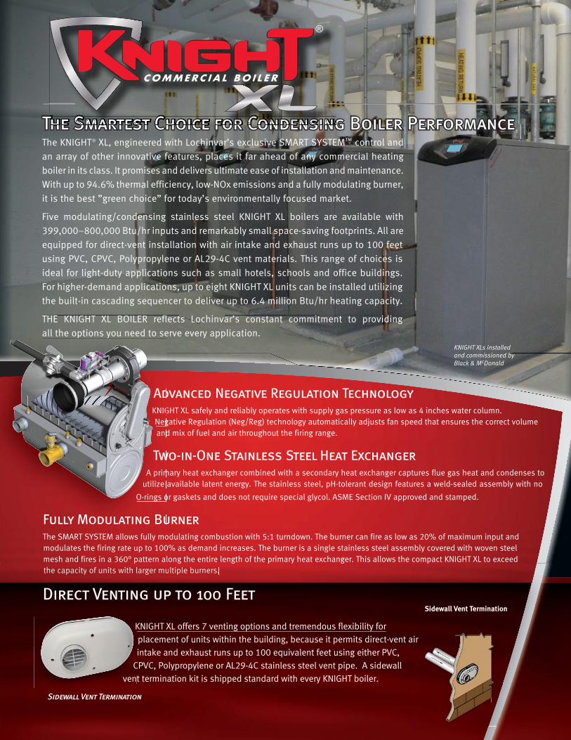
The KNIGHT® XL, engineered with Lochinvar’s exclusive SMART SYSTEM™ control and
an array of other innovative features, places it far ahead of any commercial heating
boiler in its class. It promises and delivers ultimate ease of installation and maintenance.
With up to 94.6% thermal efficiency, low-NOx emissions and a fully modulating burner,
it is the best ”green choice” for today’s environmentally focused market.
Five modulating/condensing stainless steel KNIGHT XL boilers are available with
399,000–800,000 Btu/hr inputs and remarkably small space-saving footprints. All are
equipped for direct-vent installation with air intake and exhaust runs up to 100 feet
using PVC, CPVC, Polypropylene or AL29-4C vent materials. This range of choices is
ideal for light-duty applications such as small hotels, schools and office buildings.
For higher-demand applications, up to eight KNIGHT XL units can be installed utilizing
the built-in cascading sequencer to deliver up to 6.4 million Btu/hr heating capacity.
THE KNIGHT XL BOILER reflects Lochinvar’s constant commitment to providing
all the options you need to serve every application.
Advanced Negative Regulation TechnologyKNIGHT XL safely and reliably operates with supply gas pressure as low as 4 inches water column.
Negative Regulation (Neg/Reg) technology automatically adjusts fan speed that ensures the correct volume
and mix of fuel and air throughout the firing range.
Two-in-One Stainless Steel Heat ExchangerA primary heat exchanger combined with a secondary heat exchanger captures flue gas heat and condenses to
utilize available latent energy. The stainless steel, pH-tolerant design features a weld-sealed assembly with no
O-rings or gaskets and does not require special glycol. ASME Section IV approved and stamped.
Fully Modulating Burner The SMART SYSTEM allows fully modulating combustion with 5:1 turndown. The burner can fire as low as 20% of maximum input and
modulates the firing rate up to 100% as demand increases. The burner is a single stainless steel assembly covered with woven steel
mesh and fires in a 360° pattern along the entire length of the primary heat exchanger. This allows the compact KNIGHT XL to exceed
the capacity of units with larger multiple burners.
KNIGHT XLs installedand commissioned byBlack & McDonald
The Smartest Choice for Condensing Boiler Performance
p g g p y g p
ththee cacapapap cicitytyy ooff ununititss wiwithth llarargegerr mumultltipiplele bbururnenersrs.
KNIGHT XL offers 7 venting options and tremendous flexibility for
placement of units within the building, because it permits direct-vent air
intake and exhaust runs up to 100 equivalent feet using either PVC,
CPVC, Polypropylene or AL29-4C stainless steel vent pipe. A sidewall
vent termination kit is shipped standard with every KNIGHT boiler.
K
C
ven
Sidewall Vent Termination
Sidewall Vent Termination
The Smaaaartest Choice fooooooorrrrrrrr CCCCCCCCCooooooooonnnnnnnddddeeennnnnnsssssss ngThe Smaaaartest Choice fooooorrrrrrrr CCCCCCCCCoooooooonnnnnnnndddddeeeeeeennnnnnnssssssssiiiing
all the options you need to se
AdKKNIG
Neg
and
TTwAA prim
uutilize
OO-rings o
Fully Modulating Bu
Direct Venting up to 100 Feet

• Multi-Color Graphic LCD Display• Navigation Dial• USB Port• Ability to control up to three different setpoint temperatures• Compatibility with Copper-Fin II Non-Condensing Boiler to Create a Front-End Loading System• Boilers with Different Inputs can be Cascaded Together to Maximize Boiler Plant Turndown• Modbus Capability (Optional) • DHW Modulation Limiting• DHW Night Setback*• 0-10 V Boiler Rate Output• 0-10V Signal to control variable speed boiler pump*• 0-10V System Pump Signal Input*• Heat Demand from 0-10V Input• Installer Can Program Name and Number into the Boiler• Installer Adjustable Freeze Protection Parameters• Separately adjustable SH/DHW Switching times*• Installer access to BMS and ramp delay settings
*Exclusive to Lochinvar Smart System
Refined Design Puts More Controland Information at your Fingertips
The Smartest Choice for Condensing Boiler Performance
Room Air VerticalDirect Vent Vertical Direct Vent Vertical*Room Air SidewallDirect Vent Sidewall Direct Vent Sidewall*Vertical w/Sidewall Air
Advannced featuurrees iincclude::
*Optional Concentric Vent Kit Sold Separately (for 400-601 Models)
7 Flexible Venting Options
Lead-Lag Cascade
The “lead” boiler modulates with demand to capacity. As demand increases,
additional boilers fire and modulate to capacity. This continues, with additional
boilers firing and modulating to capacity until all units are operating. Every 24
hours, the SMART SYSTEM automatically shifts the lead boiler role to the next
in the sequence, distributing lead-lag runtimes equally.
Efficiency Optimized Cascade
This feature optimizes the modulation capabilities of the Boiler Plant while
evenly distributing run time across all cascaded boilers. Every 24 hours the
SMART SYSTEM automatically shifts the 1st boiler on role to the next in the
sequence, distributing run time equally.
SMART SYSTEM Cascade option allows 2 - 8 boilers to be sequenced.
New Selectable Cascade OptionsWhen muultiiple KKNIGHT boileers aaree iinstalledd together,r, tthhee SSMARTT SSYYSYSSTEM built--inn sseeqquencer can be setet foor ““Leadad-Lag” cascaade oor ““Efficienccy Optimizzedd” caascadde ooppeeratioon.
At-a-Glance Color Coding
Yellow ScreenMaintenance due - shows
the installer’s name and
number on the display.
Red ScreenLockout mode.
Blue ScreenNormal system
operation.
R D P M C

> High Voltage Terminal Strip > 120 VAC / 60 Hertz / 1 Phase Power Supply
> Three sets of Pump Contacts with Pump Relays
> Low Voltage Terminal Strip > 24 VAC Device Relay
> Proving Switch Contacts
> Flow Switch Contacts
> Alarm on Any Failure Contacts
> Runtime Contacts
> DHW Thermostat Contacts
> 3 Space Heat Thermostat Contacts
> System Sensor Contacts
> DHW Tank Sensor Contacts
> Outdoor Air Sensor Contacts
> Cascade Contacts
> 0-10 VDC BMS External Control Contact
> 0-10VDC Boiler Rate Output Contacts
> 0-10VDC Variable Speed System Pump Signal Input
> 0-10VDC Signal to Control Variable Speed Boiler Pump
> Modbus Contacts
> Time Clock> Data Logging > Hours Running, Space Heating
> Hours Running, Domestic Hot Water
> Ignition Attempts
> Last 10 Lockouts
> Other Features > Low Water Flow Safety Control & Indication > Password Security
> Inlet & Outlet Temperature Readout
> Customizable Freeze Protection Parameters
> Custom Maintenance Reminder with Contractor Info
*Exclusive feature, available only from Lochinvar
Standard Features> Up to 94.6% Thermal Efficiency> Modulating Burner with 5:1 Turndown > Direct-Spark Ignition
> Low NOx Operation
> Sealed Combustion
> Low Gas Pressure Operation
> ASME Stainless Steel Heat Exchanger > ASME Certified, ”H” Stamped
Gasketless Heat Exchanger
> 160 psi Working Pressure
> 50 psi ASME Relief Valve
> Highly efficient, condensing design
> Vertical & Horizontal Direct-Vent > Category IV venting up to 100 feet
> PVC, CPVC, Polypropylene or AL29-4C Venting
up to 100 Feet
> Factory Supplied Sidewall Vent Termination
> Smart System Control> Other Features > On/Off Switch
> Adjustable High Limit w/ Manual Reset
> Automatic Reset High Limit
> Flow Switch
> Flue Temperature Sensor
> Low Air Pressure Switch
> Temperature & Pressure Gauge
> Adjustable Leveling Legs
> Condensate Trap
> Zero Clearances to Combustible Material
> 10 Year Limited Warranty (See Warranty)
Smart System Features> SMART SYSTEM Digital Operating Control
> Multi-Color Graphic LCD Display w/ Navigation Dial> Three Reset Temperature Inputs with curves for three set point temperature inputs> Built in Cascading Sequencer for up to 8 Boilers
> Multiple Size Boiler Cascade > Lead Lag > Efficiency Optimization > Outdoor Reset Control with Outdoor Air Sensor > Programmable System Efficiency Optimizers > Night Setback > DHW Night Setback > Anti-Cycling > Outdoor Air Reset Curve > Ramp Delay > Boost Temperature & Time > Three Pump Control > System Pump With Parameter for Continuous Operation
> Boiler Pump With Variable Speed Pump Control* > Domestic Hot Water Pump > Domestic Hot Water Prioritization > DHW tank piped with priority in the boiler loop > DHW tank piped as a zone in the system with the pumps controlled by the Smart System > DHW Modulation Limiting > Separately Adjustable SH/DHW Switching Times* > Building Management System Integration > 0-10VDC Input to Control Modulation or Set Point
> 0-10VDC Input Signal from Variable Speed System Pump*
> 0-10VDC Modulation Rate Output
> 0-10VDC Input to Enable/Disable call for heat
> Access to BMS Settings through Display
KBX-05 (Revised KBX-05 6/11) FG-5M-2/12-Printed in U.S.A.
3 0 0 M a d d o x S i m p s o n P a r k w a y, L e b a n o n, T N 3 7 0 9 0 | 6 1 5 - 8 8 9 - 8 9 0 0 | f a x : 6 1 5 - 5 4 7- 1 0 0 0 | w w w . L o ch i n v a r .c om
Knight® XL Boiler Dimensions and Specifications
Model Number Guide
KB N 701 M13
Mod
el
Firing Controls
Natural G
as
Btu/hr Input
Input Net Model Min Max Thermal Output I=B=RNumber MBH MBH Efficiency MBH MBHKBN400 80 399 93.3% 373 324
KBN501 100 500 93.3% 467 406
KBN601 120 600 94.6% 567 493
KBN701 140 700 94.3% 660 574
KBN801 160 800 94.0% 752 654
A B C D E F G H I J K Gas Water Air Vent Shipping Conn. Conn. Inlet Size Wt. (lbs.) 42-1/2” 15-1/2” 27-3/4” 3-3/4” 20-3/4” 21” 14” 34” 34” 2” 18-3/4” 1” 1-1/2” 4” 4” 280
42-1/2” 15-1/2” 31-1/2” 3-3/4” 25-1/2” 21” 14” 32-1/2” 36” 2” 18” 1” 1-1/2” 4” 4” 310
42-1/2” 15-1/2” 36-1/4” 3-3/4” 25” 21” 14” 36” 32-3/4” 5-1/2” 19-1/2” 1” 2” 4” 4” 340
42-1/2” 15-1/2” 40-1/4” 3-3/4” 29” 23” 17” 36” 32-3/4” 3-1/4” 23-1/2” 1” 2” 4” 6” 370
42-1/2” 15-1/2” 45-1/4” 3-3/4” 33-1/4” 23” 17” 36” 32-3/4” 3-1/4” 27-3/4” 1” 2” 4” 6” 405
Notes: Indoor installation only. All information subject to change. Change “N” to “L” for LP gas models.
Knight XL Boiler,
Natural Gas,
700,000 Btu/hr input,
M13 firing controls
night XL Boiler Dimensions and Spec
LEFT SIDE
FRONTBACK
8"
39-1/2"
13-3/4"
18-3/4"
H
K
D
GF
EC
9"
A
1-1/4"1/4" - ADJUSTABLE
AIR INLET
FLUE
LOW VOLTAGEELECTRICALCONNECTIONS
GAS
INLET OUTLET
HEATEXCHANGERDRAIN3/4" NPT
CONDENSATEDRAIN
FLUE
B
I
J
HIGH VOLTAGEELECTRICALCONNECTIONS
38-3/4"
3-1/2"
Patent
Pending
Optional Equipment > Alarm Bell> Condensate Neutralization Kit)> Concentric Vent Kit (KB400-KB601)> BMS Gateway to LON or BacNet> High & Low Gas Pressure Switches w/ Manual Reset (KB501-KB801)> MODBUS Communication
> Multi Temperature Loop Control> Low Water Cutoff w/Manual Reset & Test> Boiler Circulation Pump> SMART SYSTEM PC Software> Stainless Steel Vent Kits (KB701-KB801)> Stack Frame
Firing Codes > M9 Standard Construction
> M7 California Code
> M13 CSD1 / FM / GE Gap (KB501-KB801)
Knight XL Heating Boiler Dimensions and Specifications
L
OCHINVAR, LLC
LEB
ANON, TENNESSEE
brian
Line

H I G H E F F I C I E N C Y C O M M E R C I A L W A T E R H E A T E R S
OPERATING CONTROL FEATURING A BUILT-IN CASCADING SEQUENCER
UP TO 87% THERMAL EFFICIENCY
500,000 TO 2,000,000 BTU/HR
MODELS AVAILABLE IN 100% ON/OFF,2:1 TURNDOWN OR 5:1 TURNDOWN
LESS THAN 20 ppm NOx
L o c h i n v a r .c o m
Up to 87%Thermal Efficiency
brian
Text Box
One Water Heater Model: PFN0752

A Symbol of Lochinvar’s Commitment to Excellence!Since its introduction in 1986, the Power-Fin® water heater has carried
on the Lochinvar tradition of always giving more to our customers. The
latest generation of Power-Fin continues to evolve, with new “Built-in
Advantages” from Lochinvar. These include expanded burner modulation
and the advanced SMART SYSTEM™ operating control, including a built-
in cascading sequencer for up to eight water heaters.
Power-Fin water heaters can be installed with Lochinvar’s advanced
Lock-Temp® storage tanks, in a wide variety of combinations to meet
system sizing requirements. “Factory packaged” water heater/storage
tank systems can be built to your specifications, with all piping installed,
and shipped on I-beam skids.
Infinite ModulationWith thermal efficiencies up to 87%, Power-Fin water heaters feature infinitely modulating
burner firing rates (turndown), precisely matching the firing rate to domestic water load
requirements. The result is better overall efficiency and less cycling.
Power-Fin water heaters may be specified as either 5:1 turndown (502 - 2001), 2:1 turndown
(1501 - 2001), or ON/OFF (502 - 1302). With 5:1 turndown the burner fires as low as 20% of
maximum input when demand is lowest and increases the firing rate up to 100% as demand
increases. Models with 2:1 turndown modulate from 50% to 100% of maximum input.
Gasketless Heat ExchangerThe Power-Fin heat exchanger features an array of 20 to 24 copper-finned tubes surrounding
the burner for maximum heat transfer. Lochinvar also pioneered the “gasketless”
heat exchanger, which eliminates the use of O-rings and gaskets. Because of the
time-proven reliability of this design, the Power-Fin heat exchanger is backed by a
5-year limited warranty.
The vertical heat exchanger also makes Power-Fin compact and easy to handle, install
and service. All access for installation or service is through the front or back, and
multiple units can line up side-by-side with zero clearance to combustibles.
First Power-Fin in 1986
e infin
dom
200
res as
100%
maxim
ubes
the “
Beca
s ba
andl
or ba
bles
nitely moodulatingg
mestic waater loadd
1), 2:1 tuurndownn
s low as 20% ofof
% as demmand
mum inpuut.
s surrounddingg
“gasketleesss””
ause of tthee
acked by a a
le, instaalllll
ack, anndd
.

23-1/4" (502 - 1302)
27-1/4" (1501 - 2001)
zero clearanceto combustibles
Lead-Lag RotationEvery 24 hours, the SMART SYSTEM automatically shifts the lead water
heater role to the next unit in the sequence. This rotation ensures long
life by distributing “lead-lag” run times equally over each unit in the system.
Control Features
Easy to use – makes setup and service a breeze
2-Line 16-character LCD display of setup, system status and diagnostic data in words, not codes
Water heater pump control:> Pump delay w/freeze protection> Pump exercise
High-voltage terminal strip:> 120 Vac input to water heater> 120 Vac output to pump
Low-voltage terminal strip with 22 points of connection
Built-in cascading sequencer controls up to 8 units without the added cost of a separate third-party sequencer
0-10Vdc BMS input for easy integration intobuilding management systems
Password security
Interface for optional SMART SYSTEM PC software for advanced setup and diagnostics
C FControl Features

Venting Solutions
*Requires factory-supplied vent kit with M firing code models. See Specification Chart for specific venting sizes based on venting materials category type.
Power-Fin features flexible two-pipe, independent air inlet and exhaust vent
piping. When equipped with 100% On/Off (F Models) Firing Controls (502 -
1302), 2:1 (B Models) Modulating Firing Controls (1501 - 2001), the Power-Fin
utilizes Category I, Type B vent material and is ideal for replacement/retrofit
applications with an existing vent stack. When equipped with 5:1 (M Models)
Modulating Firing Controls (502 - 2001), the Power-Fin requires Category IV,
corrosion-resistant, sealed vent pipe. Category IV models provide more venting
flexibility and expanded turndown. In addition, (M Models) Modulating units may
be installed as Category II appliances, allowing multiple units to be manifolded
together into a common vent stack – giving you even more design options!
Direct Venting*Horizontal or vertical vent-ing up to 50 equivalent feet. Draws combustion air up to50 feet from the same pres-sure zone using Category IV vent materials. This option only available with 5:1 (M#) firing code models.
Vertical VentingUsing Category I or Category IV vent materials
Common Venting*Vents multiple units horizontally through one vent termination and draws combustion air from the room, roof or sidewall. Category IV to II conversion kit required with (M#) firing code models.
Sidewall Venting*Horizontal venting up to 50 equivalent feet using Category IV vent materials.
DirectAire Horizontal*Vents horizontally up to 50 equivalent feet and draws combustion air up to 50 feet from a different pressure zone using Category IV vent materials. This option only available with 5:1 (M#) firing code models.
DirectAire Vertical*Vertical venting up to 50 equivalent feet. Draws combustion air up to 50 feet from a different pressure zone using Category I or IV vent materials.

Engineered and Packaged Systems for Ultimate FlexibilityLochinvar’s unique “engineered systems” approach to water
heating provides the flexibility to package the heating unit(s)
with the exact size and capacity storage tank that is needed for
any given application.
For example: Use a high-output Power-Fin with a small tank for
applications where the demand is almost constant, or team a
low-output water heater with a large tank for short-term, high
draw situations. Whatever the need, Lochinvar has a Lock-Temp
tank to match it – from 100 to 5000 gallons.
Each package system can be custom-configured to the exact
specifications and available space of each job.
Power-Fin Package Systems are: > Pre-engineered
> Pre-piped
> Pre-tested
> Pre-assembled and shipped on
channel iron skids – ready for installation
PFX-03 (Revised PFX-03 10/10) FG-5M-3/12-Printed in U.S.A.
HLW
3 0 0 M a d d o x S i m p s o n P a r k w a y, L e b a n o n, T N 3 7 0 9 0 | 6 1 5 - 8 8 9 - 8 9 0 0 | f a x : 6 1 5 - 5 4 7- 1 0 0 0 | w w w . L o ch i n v a r .c om
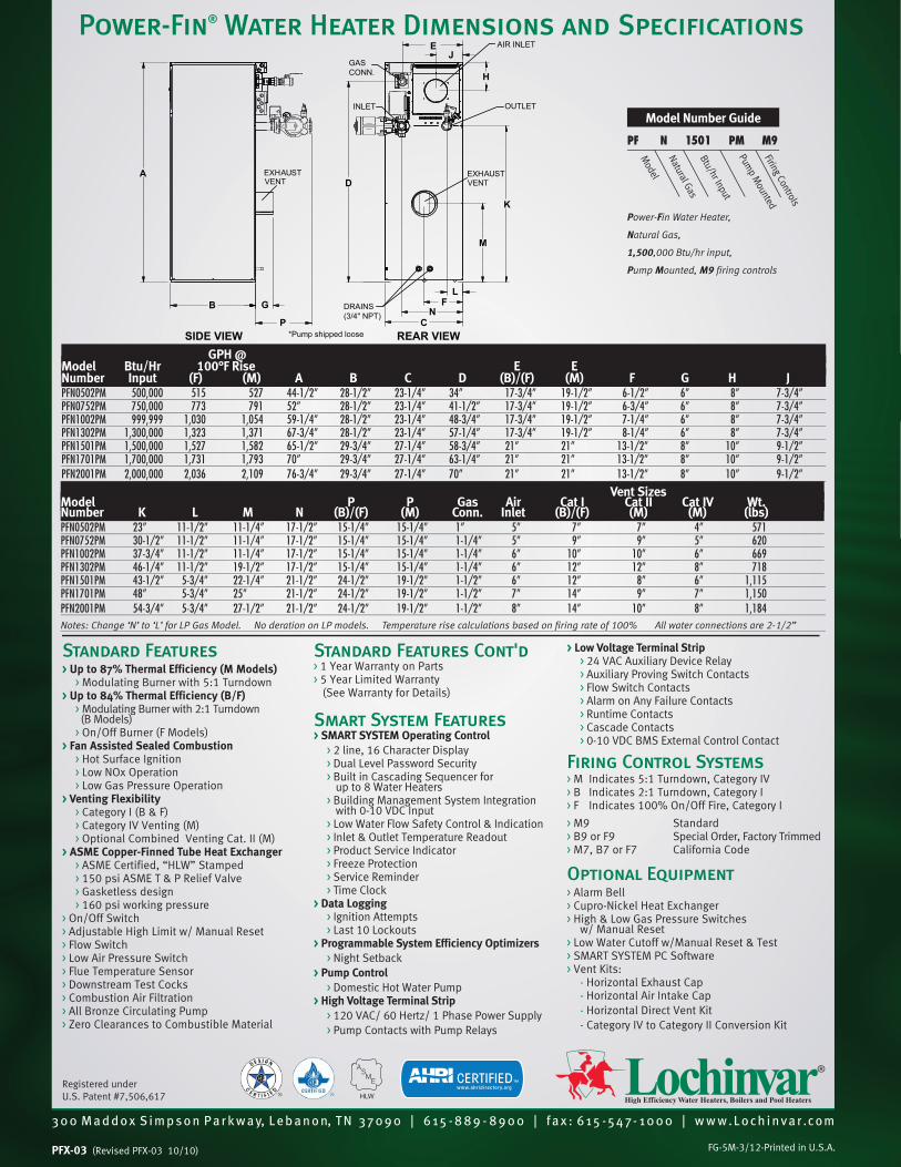
Power-Fin® Water Heater Dimensions and Specifications
> Low Voltage Terminal Strip > 24 VAC Auxiliary Device Relay
> Auxiliary Proving Switch Contacts
> Flow Switch Contacts
> Alarm on Any Failure Contacts
> Runtime Contacts
> Cascade Contacts
> 0-10 VDC BMS External Control Contact
Firing Control Systems> M Indicates 5:1 Turndown, Category IV
> B Indicates 2:1 Turndown, Category I
> F Indicates 100% On/Off Fire, Category I
> M9 Standard
> B9 or F9 Special Order, Factory Trimmed
> M7, B7 or F7 California Code
Optional Equipment > Alarm Bell
> Cupro-Nickel Heat Exchanger
> High & Low Gas Pressure Switchesw/ Manual Reset
> Low Water Cutoff w/Manual Reset & Test
> SMART SYSTEM PC Software
> Vent Kits:
- Horizontal Exhaust Cap
- Horizontal Air Intake Cap
- Horizontal Direct Vent Kit
- Category IV to Category II Conversion Kit
Standard Features> Up to 87% Thermal Efficiency (M Models) > Modulating Burner with 5:1 Turndown
> Up to 84% Thermal Efficiency (B/F) > Modulating Burner with 2:1 Turndown
(B Models)
> On/Off Burner (F Models)
> Fan Assisted Sealed Combustion > Hot Surface Ignition
> Low NOx Operation
> Low Gas Pressure Operation
> Venting Flexibility > Category I (B & F)
> Category IV Venting (M)
> Optional Combined Venting Cat. II (M)
> ASME Copper-Finned Tube Heat Exchanger > ASME Certified, “HLW” Stamped
> 150 psi ASME T & P Relief Valve
> Gasketless design
> 160 psi working pressure
> On/Off Switch
> Adjustable High Limit w/ Manual Reset
> Flow Switch
> Low Air Pressure Switch
> Flue Temperature Sensor
> Downstream Test Cocks
> Combustion Air Filtration
> All Bronze Circulating Pump
> Zero Clearances to Combustible Material
Standard Features Cont'd> 1 Year Warranty on Parts
> 5 Year Limited Warranty
(See Warranty for Details)
Smart System Features> SMART SYSTEM Operating Control > 2 line, 16 Character Display
> Dual Level Password Security
> Built in Cascading Sequencer for up to 8 Water Heaters
> Building Management System Integration with 0-10 VDC Input
> Low Water Flow Safety Control & Indication
> Inlet & Outlet Temperature Readout
> Product Service Indicator
> Freeze Protection
> Service Reminder
> Time Clock
> Data Logging > Ignition Attempts
> Last 10 Lockouts
> Programmable System Efficiency Optimizers > Night Setback
> Pump Control > Domestic Hot Water Pump
> High Voltage Terminal Strip > 120 VAC/ 60 Hertz/ 1 Phase Power Supply
> Pump Contacts with Pump Relays
Model Number Guide
PF N 1501 PM M9
Mod
el
Firing Controls
Natural G
asB
tu/hr Input
Power-Fin Water Heater,
Natural Gas,
1,500,000 Btu/hr input,
Pump Mounted, M9 firing controls
Pump M
ounted
GPH @ Model Btu/Hr 100°F Rise E ENumber Input (F) (M) A B C D (B)/(F) (M) F G H JPFN0502PM 500,000 515 527 44-1/2” 28-1/2” 23-1/4” 34” 17-3/4” 19-1/2” 6-1/2” 6” 8” 7-3/4”PFN0752PM 750,000 773 791 52” 28-1/2” 23-1/4” 41-1/2” 17-3/4” 19-1/2” 6-3/4” 6” 8” 7-3/4”PFN1002PM 999,999 1,030 1,054 59-1/4” 28-1/2” 23-1/4” 48-3/4” 17-3/4” 19-1/2” 7-1/4” 6” 8” 7-3/4”PFN1302PM 1,300,000 1,323 1,371 67-3/4” 28-1/2” 23-1/4” 57-1/4” 17-3/4” 19-1/2” 8-1/4” 6” 8” 7-3/4”PFN1501PM 1,500,000 1,527 1,582 65-1/2” 29-3/4” 27-1/4” 58-3/4” 21” 21” 13-1/2” 8” 10” 9-1/2”PFN1701PM 1,700,000 1,731 1,793 70” 29-3/4” 27-1/4” 63-1/4” 21” 21” 13-1/2” 8” 10” 9-1/2”PFN2001PM 2,000,000 2,036 2,109 76-3/4” 29-3/4” 27-1/4” 70” 21” 21” 13-1/2” 8” 10” 9-1/2”
Vent SizesModel P P Gas Air Cat I Cat II Cat IV Wt.Number K L M N (B)/(F) (M) Conn. Inlet (B)/(F) (M) (M) (lbs)PFN0502PM 23” 11-1/2” 11-1/4” 17-1/2” 15-1/4” 15-1/4” 1” 5” 7” 7” 4” 571 PFN0752PM 30-1/2” 11-1/2” 11-1/4” 17-1/2” 15-1/4” 15-1/4” 1-1/4” 5” 9” 9” 5” 620PFN1002PM 37-3/4” 11-1/2” 11-1/4” 17-1/2” 15-1/4” 15-1/4” 1-1/4” 6” 10” 10” 6” 669PFN1302PM 46-1/4” 11-1/2” 19-1/2” 17-1/2” 15-1/4” 15-1/4” 1-1/4” 6” 12” 12” 8” 718PFN1501PM 43-1/2” 5-3/4” 22-1/4” 21-1/2” 24-1/2” 19-1/2” 1-1/2” 6” 12” 8” 6” 1,115PFN1701PM 48” 5-3/4” 25” 21-1/2” 24-1/2” 19-1/2” 1-1/2” 7” 14” 9” 7” 1,150PFN2001PM 54-3/4” 5-3/4” 27-1/2” 21-1/2” 24-1/2” 19-1/2” 1-1/2” 8” 14” 10” 8” 1,184Notes: Change ‘N’ to ‘L’ for LP Gas Model. No deration on LP models. Temperature rise calculations based on firing rate of 100% All water connections are 2-1/2”
Registered under
U.S. Patent #7,506,617
B G
P C
J
K
M
L
N
brian
Line

23 Bertrand Avenue, Toronto, Ontario, Canada, M1L 2P3Tel:(416)755-2291 Fax(Main):(416)759-9101www.armstrongintegrated.com
Project Name: California Square
Name: MATT HITT
Reference: 303772.1.1
Location:
Engineer:
Date: 2012/5/14
Pumps ScheduleTag No. Qty Series Size Flow Head Motor Speed Electrics
P-1 1 4030 3x2.5x8 175 USgpm 55 ft 5 hp 1800 208/3/60
2012/05/14, 09:46, Matt Hitt, Plumber's Supply Co., Inc., Page: 1 / 3
brian
Text Box
2 Hot Water Pumps

Project # :303772.1 rev1Submittal
Model: 4030-3x2.5x8-5 hp
Type : HORZ
Project Number: 303772.1.1 Representative:Name: California Square
Reference: 303772.1.1 Phone: , Fax:
Project Location: Order No: Date: 5/14/2012
Engineer: Submitted by: Matt Hitt Date: 5/14/2012
Contractor: Approved by: Date:
PUMP DESIGN DATA
Tag Num P-1
Service HW/CW LoopLocation
Qty 1
Duty Flow 175 USgpmDuty Head 55 ftPipe Orientation SinglePump Run Qty 1Suction Pressure 0 psigFluid:Percent WaterOp Temp 60 FViscosity 31 SSUSpecific Gravity 1.0000Suction (inches) 3Discharge 2.5
MOTOR DESIGN DATA
Motor Supplier Factory Choice
Motor Size 5 hp
Mtr Frame Num. 184T
Motor Enclosure ODP
Power Supply 208/3/60
Insulation Classes Class F Insulation
Inverter Motor Type [none]
Motor RPM 1800
Motor Efficiency NEMA Prem (12.12) 89.5%
MATERIALS OF CONSTRUCTION
Construction BF
Rating ANSI-125
Casing (Volute) Cast Iron (A48-30)
Impeller Bronze (B584-844)
Shaft Sleeve 304 SS
Flexible Couplings Standard
Pump Shaft Carbon Steel
Casing Gasket Confined Non-Asbestos Fiber
Bearings Anti-Friction Grease Lubricated
Size 3x2.5x8
MECHANICAL SEAL DESIGN DATA
Manufacturer Armstrong
Seal Type Inside Single-Spring
Manu. Code C-sc L EPSS 2A
Rotating Face Resin Bonded Carbon
Stationary Seat Silicon Carbide
Secondary Seal EPDM
Springs Stainless Steel
Rotating Hardware Stainless Steel
Fluid Type Non-Potable Fluid
Seat Elastomer EPDM (L-Cup)
Seal Armstrong 2A
Drawing
Pump casings are hydrostatically tested to 150% of maximum pump working pressure
DIMENSIONAL DATA (in, lb ) NOT for CONSTRUCTIONHA
0
HB
0
HC
0
HD
0
HE
0
HF
0
HG
0
HH
0
HL
0
HP
0
X
0
Y
0
Weight
60
2012/05/14, 09:46, Matt Hitt, Plumber's Supply Co., Inc., Page: 2 / 3

Model: 4030-3x2.5x8-5 hp
Type : HORZ
--- Admin Data --- Tag Num: P-1 Service: HW/CW Loop Location:
--- Motor Data --- Motor Size: 5 hp Motor Speed: 1800 rpm
--- Design Duty Point --- Flow: 175 usgpm Head: 55 ft Impeller: 7.788 in
--- Performance Data --- • NPSHR: 7.816 ft • Eff. @ Design: 73.60 % • BHP @ Design: 3.30 hp • Mtr Capability @ Rated Spd: 5.00 hp • %Mtr Safety: 51.41% • BEP @ Design Imp.: 74.87 % @ 218.1 usgpm • Impeller Max BHP @ Flow: 4.70 hp @ 327.2 usgpm • %max imp. range: 85.13 % • Outlet Velocity: 11.73 ft/s
Series 4030
3x2.5x8 @ 1740 rpm
0 80 160 240 320 4000
10
20
30
40
50
60
70
80
8.19 in
5.50 in
System
7.79 in
1.5 hp2 hp
3 hp
5 hp
7.5 hp
1 hp
76
76
74
74
70
70
63
63
53
53%
40
Flow (usgpm)
Head
(ft)
Water, spgr= 1.0000
PT56-1-0 (3.4.0.3)ISO/CD 9906 Grade 2
Annex D
76
CONNECTION DETAILS (in)Connection Size Rating OD #Bolts BCD Bolt Size
Inlet 3 ANSI-125 7.5 4 6 0.625
Outlet 2.5 ANSI-125 7 4 5.5 0.625
2012/05/14, 09:46, Matt Hitt, Plumber's Supply Co., Inc., Page: 3 / 3

Unit Report For 80 TonProject: ~Untitled10 04/20/2012 Prepared By: Joe Rademaker 04:30PM
Unit Information Tag Name: 80 Ton Model Number: 30RB080 Condenser Type: Air Cooled Compressor Type: Scroll Nameplate Voltage: 208/230-3-60 V-Ph-Hz Quantity: 1 Manufacturing Source: Charlotte, NC USA Refrigerant: R410A Independent Refrigerant Circuits: 2 Capacity Control Steps: 4 Minimum Capacity: 16.0 % Shipping Weight: 4335 lb Operating Weight: 4600 lb Unit Length: 95 in Unit Width: 89 in Unit Height: 90 in
Accessories and Installed Options Freeze Protection Suction Service Valves Al Fin/Cu Tube Low Sound Option Low Ambient Head Pressure Control Minimum Load Control Single Point Coil Trim Panels, Grilles, Full End Screens
Warranty Information (Note: for US & Canada only) First Year - Parts Only (Standard)
Ordering Information
Part Number Description Quantity 30RBX0805--HFG-K Packaged Chiller 1
Base Unit Freeze Protection Suction Service Valves Al Fin/Cu Tube Low Sound Option Low Ambient Head Pressure Control Minimum Load Control Single Point Coil Trim Panels, Grilles, Full End Screens
Packaged Chiller Builder NACO 3.39g Page 1 of 7
brian
Text Box
1 CHILLER

Certified Drawing for 80 TonProject: ~Untitled10 04/20/2012 Prepared By: Joe Rademaker 04:30PM
Packaged Chiller Builder NACO 3.39g Page 2 of 7

Field Wiring Diagram for 80 TonProject: ~Untitled10 04/20/2012 Prepared By: Joe Rademaker 04:30PM
Packaged Chiller Builder NACO 3.39g Page 3 of 7
jrademaker
Line

Summary Performance Report For 80 TonProject: ~Untitled10 04/20/2012 Prepared By: Joe Rademaker 04:30PM
AquaSnapTM Air-Cooled Scroll Chiller
Unit Information Tag Name: 80 Ton Model Number: 30RB080 Quantity: 1 Manufacturing Source: Charlotte, NC USA Refrigerant: R410A Independent Refrigerant Circuits: 2 Shipping Weight: 4335 lb Operating Weight: 4600 lb Unit Length: 95 in Unit Width: 89 in Unit Height: 90 in Evaporator Information Fluid Type: Fresh Water Fouling Factor: 0.00010 (hr-sqft-F)/BTU Leaving Temperature: 44.0 °F Entering Temperature: 54.0 °F Fluid Flow: 181.6 gpm Pressure Drop: 7.0 ft Condenser Information Altitude: 0 ft Number of Fans: 4 Total Condenser Fan Air Flow: 49600 CFM Entering Air Temperature: 95.0 °F Integrated Pump Information No Pump Selected
Performance Information Cooling Capacity: 76.0 Tons Total Compressor Power: 85.0 kW Total Fan Motor Power: 10.3 kW Total Unit Power (without pump): 95.3 kW Efficiency (without pump): 9.56 EER A-Weighted Sound Power Level: 95 dbA Accessories and Installed Options Freeze Protection Suction Service Valves Al Fin/Cu Tube Low Sound Option Low Ambient Head Pressure Control Minimum Load Control Single Point Coil Trim Panels, Grilles, Full End Screens Electrical Information Unit Voltage: 208/230-3-60 V-Ph-Hz Connection Type: Single Point Minimum Voltage: 187 Volts Maximum Voltage: 253 Volts
Electrical Electrical Amps Circuit 1 Circuit 2 MCA 366.5 --- MOCP 400.0 --- ICF 757.8 ---
Certified in accordance with the AHRI Water-Chilling Packages using the Vapor Compression Cycle Certification Program, which is based on AHRI Standard 550/590-2003.
Sound power measured in accordance with ANSI/AHRI Standard 370-2001.
Packaged Chiller Builder NACO 3.39g Page 4 of 7
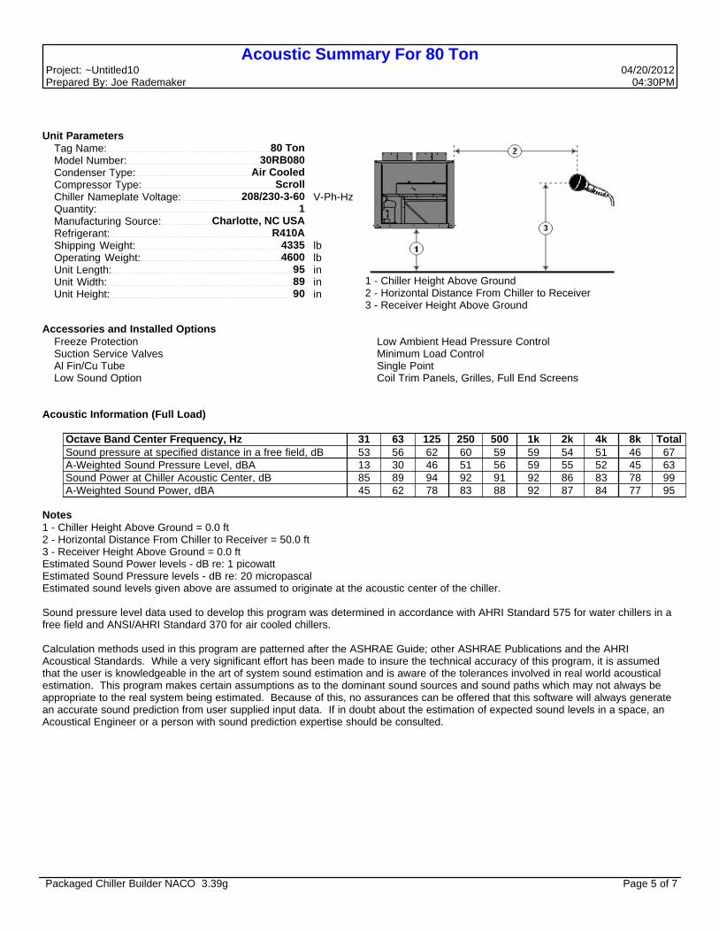
Acoustic Summary For 80 TonProject: ~Untitled10 04/20/2012 Prepared By: Joe Rademaker 04:30PM
Unit Parameters Tag Name: 80 Ton Model Number: 30RB080 Condenser Type: Air Cooled Compressor Type: Scroll Chiller Nameplate Voltage: 208/230-3-60 V-Ph-Hz Quantity: 1 Manufacturing Source: Charlotte, NC USA Refrigerant: R410A Shipping Weight: 4335 lb Operating Weight: 4600 lb Unit Length: 95 in Unit Width: 89 in Unit Height: 90 in
1 - Chiller Height Above Ground2 - Horizontal Distance From Chiller to Receiver3 - Receiver Height Above Ground
Accessories and Installed Options Freeze Protection Suction Service Valves Al Fin/Cu Tube Low Sound Option
Low Ambient Head Pressure Control Minimum Load Control Single Point Coil Trim Panels, Grilles, Full End Screens
Acoustic Information (Full Load)
Octave Band Center Frequency, Hz 31 63 125 250 500 1k 2k 4k 8k Total Sound pressure at specified distance in a free field, dB 53 56 62 60 59 59 54 51 46 67 A-Weighted Sound Pressure Level, dBA 13 30 46 51 56 59 55 52 45 63 Sound Power at Chiller Acoustic Center, dB 85 89 94 92 91 92 86 83 78 99 A-Weighted Sound Power, dBA 45 62 78 83 88 92 87 84 77 95
Notes1 - Chiller Height Above Ground = 0.0 ft2 - Horizontal Distance From Chiller to Receiver = 50.0 ft3 - Receiver Height Above Ground = 0.0 ftEstimated Sound Power levels - dB re: 1 picowattEstimated Sound Pressure levels - dB re: 20 micropascalEstimated sound levels given above are assumed to originate at the acoustic center of the chiller.
Sound pressure level data used to develop this program was determined in accordance with AHRI Standard 575 for water chillers in a free field and ANSI/AHRI Standard 370 for air cooled chillers.
Calculation methods used in this program are patterned after the ASHRAE Guide; other ASHRAE Publications and the AHRI Acoustical Standards. While a very significant effort has been made to insure the technical accuracy of this program, it is assumed that the user is knowledgeable in the art of system sound estimation and is aware of the tolerances involved in real world acoustical estimation. This program makes certain assumptions as to the dominant sound sources and sound paths which may not always be appropriate to the real system being estimated. Because of this, no assurances can be offered that this software will always generate an accurate sound prediction from user supplied input data. If in doubt about the estimation of expected sound levels in a space, an Acoustical Engineer or a person with sound prediction expertise should be consulted.
Packaged Chiller Builder NACO 3.39g Page 5 of 7

Detailed Performance Summary For 80 TonProject: ~Untitled10 04/20/2012 Prepared By: Joe Rademaker 04:30PM
Unit Information Tag Name: 80 Ton Model Number: 30RB080 Condenser Type: Air Cooled Compressor Type: Scroll Nameplate Voltage: 208/230-3-60 V-Ph-Hz Quantity: 1 Manufacturing Source: Charlotte, NC USA Refrigerant: R410A Capacity Control Steps: 4 Minimum Capacity: 16.0 % Shipping Weight: 4335 lb Operating Weight: 4600 lb Unit Length: 95 in Unit Width: 89 in Unit Height: 90 in Minimum Outdoor Operating Temp: -20 °F
Performance Information Cooling Capacity: 76.0 Tons Total Compressor Power: 85.0 kW Total Fan Motor Power: 10.3 kW Total Unit Power (without pump): 95.3 kW Efficiency (without pump): 9.56 EER
Acoustics Information A-Weighted Sound Power Level: 95 dbAEvaporator Information Fluid Type: Fresh Water Fouling Factor: 0.00010 (hr-sqft-F)/BTU Leaving Temperature: 44.0 °F Entering Temperature: 54.0 °F Fluid Flow: 181.6 gpm Pressure Drop: 7.0 ft
Condenser Information Altitude: 0 ft Number of Fans: 4 Total Condenser Fan Air Flow: 49600 CFM Entering Air Temperature: 95.0 °F
Electrical Information Unit Voltage: 208/230-3-60 V-Ph-Hz Connection Type: Single Point Minimum Voltage: 187 Volts Maximum Voltage: 253 Volts
Electrical Electrical Amps Circuit 1 Circuit 2 MCA 366.5 MOCP 400.0 ICF 757.8
Integrated Pump Information No Pump Selected
Accessories and Installed Options
Packaged Chiller Builder NACO 3.39g Page 6 of 7

Detailed Performance Summary For 80 TonProject: ~Untitled10 04/20/2012 Prepared By: Joe Rademaker 04:30PM
Freeze Protection Suction Service Valves Al Fin/Cu Tube Low Sound Option Low Ambient Head Pressure Control Minimum Load Control Single Point Coil Trim Panels, Grilles, Full End Screens
Certified in accordance with the AHRI Water-Chilling Packages using the Vapor Compression Cycle Certification Program, which is based on AHRI Standard 550/590-2003.
Sound power measured in accordance with ANSI/AHRI 370-2001.
Packaged Chiller Builder NACO 3.39g Page 7 of 7

VERTICAL HI-RISE FAN COIL UNITS
MODELS TVA, TVE, TVS, TFA, TFE, TFS, TCA, TCE, TCS ¾ THROUGH 4 TONS CAPACITY
brian
Text Box
111 Vertical Fan Coil Units TF UNIT 3/4 Ton Pipes to the Back Model # 3FRRA0-126-3RH-BRLX. 3......300 cfm or 3/4 ton capacity F......for factory use only RR.....stand alone verticle draw thru unit (no piping risers) A......available factory revision code 0......electric strip heat kw...none - 126....voltage 120/1/60 electrical - 3......3 row water coil RH.....standard production model (would also indicate riser location if used) - B......backside unit piping connections (not left or right) R......first supply diffuser location (right side) L......second supply diffuser location (left side) X......no fresh air inlet option

15
7 Drain pan, pitched in two directions, insulated on the underside.
8 Chilled water coil.
9 Hot water coil in a four pipe unit (model TFS).
10 Direct drive centrifugal fan with multi-speed P.S.C. motor.
11 Electric heater (model TFE).
12 Top supply air opening (knock out) for attachment of ductwork.
13 Control cable entry point (remote thermostat).
14 Power cable entry point.
R.A.
33"
B
86"
4"
4"
A
D
FRONT VIEWSIDE SECTION VIEW
TOPVIEW
13
11
1
2
4
3
2
510
8
9
7
6
12
14
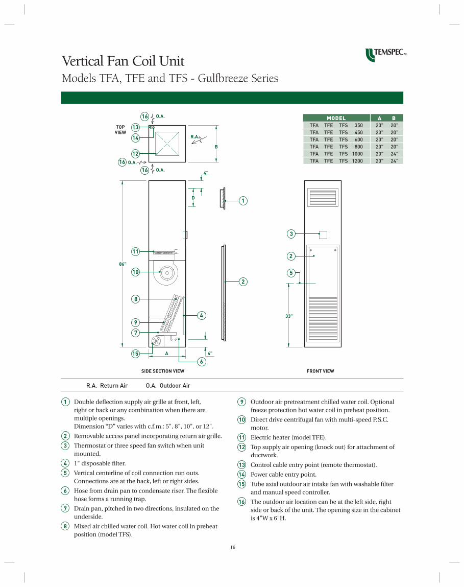
Vertical Fan Coil UnitModels TFA, TFE and TFS
1 Double defl ection supply air grille at front, left, right or back or any combination when there are multiple openings. Dimension “D” varies with c.f.m.: 5", 8", 10", or 12".
2 Removable access panel incorporating return air grille.
3 Thermostat or three speed fan switch when unit mounted.
4 1" disposable fi lter.
5 Vertical centerline of coil connection run outs. Connections are at the back, left or right sides.
6 Hose from drain pan to condensate riser. The fl exible hose forms a running trap.
MODEL A B TFA TFE TFS 350 18" 18" TFA TFE TFS 450 18" 18" TFA TFE TFS 600 20" 20" TFA TFE TFS 800 20" 20" TFA TFE TFS 1000 20" 24" TFA TFE TFS 1200 20" 24"
R.A. Return Air
16
9 Outdoor air pretreatment chilled water coil. Optional freeze protection hot water coil in preheat position.
10 Direct drive centrifugal fan with multi-speed P.S.C. motor.
11 Electric heater (model TFE).
12 Top supply air opening (knock out) for attachment of ductwork.
13 Control cable entry point (remote thermostat).
14 Power cable entry point.
15 Tube axial outdoor air intake fan with washable fi lter and manual speed controller.
16 The outdoor air location can be at the left side, right side or back of the unit. The opening size in the cabinet is 4"W x 6"H.
33"
86"
4"
4"
A
D
FRONT VIEWSIDE SECTION VIEW
11
10
8
9
7
15
4
6
1
2
3
2
5
Vertical Fan Coil UnitModels TFA, TFE and TFS - Gulfbreeze Series
1 Double defl ection supply air grille at front, left, right or back or any combination when there are multiple openings. Dimension “D” varies with c.f.m.: 5", 8", 10", or 12".
2 Removable access panel incorporating return air grille.
3 Thermostat or three speed fan switch when unit mounted.
4 1" disposable fi lter.
5 Vertical centerline of coil connection run outs. Connections are at the back, left or right sides.
6 Hose from drain pan to condensate riser. The fl exible hose forms a running trap.
7 Drain pan, pitched in two directions, insulated on the underside.
8 Mixed air chilled water coil. Hot water coil in preheat position (model TFS).
MODEL A B TFA TFE TFS 350 20" 20" TFA TFE TFS 450 20" 20" TFA TFE TFS 600 20" 20" TFA TFE TFS 800 20" 20" TFA TFE TFS 1000 20" 24" TFA TFE TFS 1200 20" 24"
R.A. Return Air O.A. Outdoor Air
R.A.
O.A.
O.A.
O.A.
B
4"
TOPVIEW
13
16
16
16
12
14
17
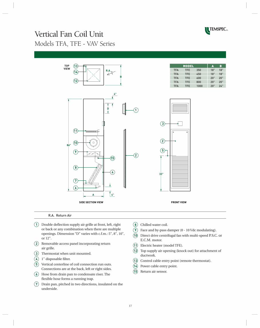
8 Chilled water coil.
9 Face and by-pass damper (0 - 10 Vdc modulating).
10 Direct drive centrifugal fan with multi-speed P.S.C. or E.C.M. motor.
11 Electric heater (model TFE).
12 Top supply air opening (knock out) for attachment of ductwork.
13 Control cable entry point (remote thermostat).
14 Power cable entry point.
15 Return air sensor.
33"
B
86"
4"
4"
A
D
FRONT VIEWSIDE SECTION VIEW
TOPVIEW
R.A.
13
12
14
11
10
8
9
7
6
15
4
1
2
3
2
5
Vertical Fan Coil UnitModels TFA, TFE - VAV Series
1 Double defl ection supply air grille at front, left, right or back or any combination when there are multiple openings. Dimension “D” varies with c.f.m.: 5", 8", 10", or 12".
2 Removable access panel incorporating return air grille.
3 Thermostat when unit mounted.
4 1" disposable fi lter.
5 Vertical centerline of coil connection run outs. Connections are at the back, left or right sides.
6 Hose from drain pan to condensate riser. The fl exible hose forms a running trap.
7 Drain pan, pitched in two directions, insulated on the underside.
MODEL A B TFA TFE 350 18" 18" TFA TFE 450 18" 18" TFA TFE 600 20" 20" TFA TFE 800 20" 20" TFA TFE 1000 20" 24"
R.A. Return Air

19 19
ARCHITECTURAL DETAILS
Attention should be paid to the height of drywall which encapsulates ductwork in a bulkhead. Note the height of the side supply air opening shown in the submittals and ensure that the drywall does not interfere with the side wall grille. Make allowance for the 1" fl ange around the grille. Call Temspec at the time of submittal review if side supply air openings need to be lowered or rotated to a vertical position to avoid interference with walls or doors.
Temspec does not include wall sleeves which might be needed to bridge a gap between the grille collar on the unit and the drywall surface, howsoever caused. Also fl oor sleeves, extension sleeves through shear walls and extension of thermostat speed switch wiring through shear walls are not included.
HANDLING
The fan coil units must be handled with the due care required for an HVAC unit. Avoid dropping or jarring the unit during off-loading and moving the unit into position. Do not lift the unit using the riser pipes.
INSTALLATION
Unless otherwise requested by the customer at the time of shop drawing approval, the cabinet insulation is left intact, covering the supply air openings and, if applicable, the secondary return air opening. The reasons for this are:
• To provide a measure of protection from wind driven rain or snow entering the unit before the windows are installed.
• To prevent construction dust entering the unit.
The installer is responsible for cutting out the insulation and buttering the cut edge prior to installing the grilles.
Use solder to connect the risers. Do not use Silfos (brazing) as this will cause the pipe to overheat and the insulation to be damaged. Ensure that the horizontal run-out from each riser is centered in the slot in the cabinet and that the run-out from the riser is at 90º as it enters the cabinet, prior to soldering the risers. Anchoring the risers to the fl oor slabs is the responsibility of the contractor. Shim the unit plumb. It is not necessary to use a pad under the unit. Fire stopping the fl oor opening and making good the riser insulation at the fl oor opening is the responsibility of the contractor. Check that the drain hose is not kinked before soldering the condensate riser. If the risers incorporate expansion compensation loops, remove the support brackets after anchoring the risers.
The fan coil unit has compression fi ttings or unions at the shut off valves. These fi ttings must be tightened prior to pressure testing the system by the contractor as part of the installation procedure. Mechanical fi ttings can loosen during transportation and handling.
The coil is pressure tested hydrostatically at the factory using a propylene glycol solution. Trace amounts of this solution are allowed to remain in the coil to ensure that the coil does not freeze during transportation.
The interior of the unit must be vacuumed clean before the unit is started up. This includes fan motor windings.
TWO-WAY CONTROL VALVES
When two way valves are used, pump and chiller bypass or pump speed control must be included in the system. This is necessary to ensure that the close-off pressure rating of the valve is not exceeded. The maximum close-off pressure rating is given in the submittals.
ELECTRICAL CONNECTION
It is assumed that the fan coil unit will be in a dedicated electrical circuit. If the unit is to be in a circuit which includes electrical outlets or other electrical devices, Temspec must be informed prior to releasing the units for production as a power fuse might have to be incorporated.
ACCESSORIES
Do not install grilles or thermostats until after the walls have been painted. Caution the painter against spraying over the labels on the front cover of the unit.
Installation Guidelines

20
Pipe Connections for Units Without RisersModels TVA, TVE, TVS, TFA, TFE and TFS
Power and Control Cable Entry PointsModels TVA, TVE, TVS, TFA, TFE and TFS
2 5/8"
33" 33"
7"
SUPPLY AND RETURN CONNECTIONS (TWO)1/2" OR 3/4" DIA. COPPER TUBE
CONDENSATE CONNECTION5/8" ID. HOSE
REAR OR SIDE VIEW
MODELS
TVA, TVE, TFA, TFE
CL
REAR OR SIDE VIEW
2 5/8"
5 1/4"
3 3/4" 3 3/4"
SUPPLY AND RETURN CONNECTIONS (FOUR)1/2" OR 3/4" DIA. COPPER TUBE
CONDENSATE CONNECTION5/8" ID. HOSE
MODELS
TVS, TFS
CL
1 1/2"
2"
2"
Ø 7/8" HOLECABLE ENTRYEACH SIDE
Ø 7/8" HOLECABLE ENTRY
10 3/4"
44 5/16"
SIDE VIEW
MODELS
TVA, TVE, TVS
MODELS
TFA, TFE, TFS
PLAN VIEW
FRONTOF UNIT
FRONTOF UNIT
CL

21
Outdoor Air Intake Opening
Secondary Return Air Opening
6"
4"
K
6"
K
VIEW ON LEFT OR RIGHT SIDE OF UNIT
O.A. OPENING WITH MANUAL SLIDING DAMPER OR MOTORIZED DAMPER
O.A OPENING WITH MANUAL SLIDING DAMPER OR MOTORIZED DAMPER
VIEW ON BACK OF UNIT
F.F.L
BACKFRONT RISERS
THIS SIDE
1"
4"
1"
CL
14"1 1/2"
5"
1
43
2
• For model TV units, K = 1/2".
• For model TF and TC units, K = 2".
• If a circular opening is preferred, please call the factory for details.
NOTES
1 Fan coil cabinet.
2 Secondary return air opening.
3 Secondary return air grille with fi lter media.
4 Sleeving collar.
NOTES
• The opening can be in the back panel or in either side.
• The fan coil unit is a draw-through type and the drainpan is low in the unit. This restricts the height of the opening to the 1 ½" dimension shown above.
22
2
4
3
1
5
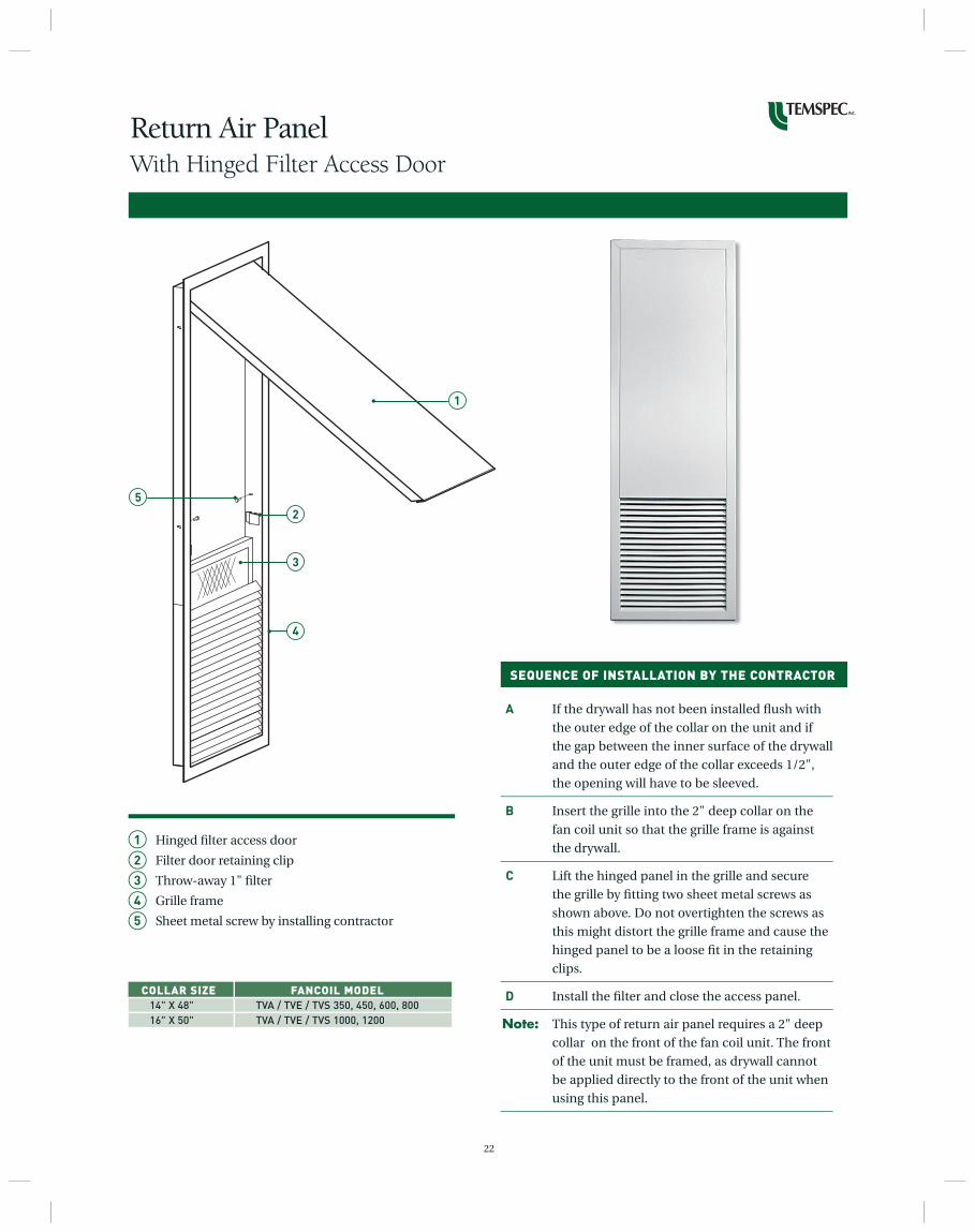
Return Air PanelWith Hinged Filter Access Door
A If the drywall has not been installed fl ush with
the outer edge of the collar on the unit and if
the gap between the inner surface of the drywall
and the outer edge of the collar exceeds 1/2",
the opening will have to be sleeved.
B Insert the grille into the 2" deep collar on the
fan coil unit so that the grille frame is against
the drywall.
C Lift the hinged panel in the grille and secure
the grille by fi tting two sheet metal screws as
shown above. Do not overtighten the screws as
this might distort the grille frame and cause the
hinged panel to be a loose fi t in the retaining
clips.
D Install the fi lter and close the access panel.
Note: This type of return air panel requires a 2" deep
collar on the front of the fan coil unit. The front
of the unit must be framed, as drywall cannot
be applied directly to the front of the unit when
using this panel.
1 Hinged fi lter access door
2 Filter door retaining clip
3 Throw-away 1" fi lter
4 Grille frame
5 Sheet metal screw by installing contractor
COLLAR SIZE FANCOIL MODEL 14" X 48" TVA / TVE / TVS 350, 450, 600, 800 16" X 50" TVA / TVE / TVS 1000, 1200
SEQUENCE OF INSTALLATION BY THE CONTRACTOR

23
Flush Mounted Return Air/Access PanelWith Quarter Turn Fasteners
1 Return air grille/access panel with quarter turn
fasteners
2 Bottom hook of access panel
3 Throw-away 1" fi lter
4 1/4 turn fastener with slotted head and square
shaft
5 Pawl of the 1/4 turn fastener
6 Pawl lock screw
7 Plastic washer
8 Spring retainer
9 1/2" deep collar around return air opening on
fan coil unit
10 1/2" drywall
A Insert the square shaft of the fastener into
the recessed hole in the panel. Put the plastic
washer onto the shaft followed by the retainer.
Push the retainer as far as possible so that it
fi rmly holds the fastener in place.
B Put the pawl onto the shaft and position it so
that the pawl pulls the panel tightly against the
wall. Tighten the lock screw in the pawl.
C Install the fi lter in the panel, hook the access
panel over the bottom collar of fan coil unit,
rotate the panel so that it is against the wall,
turn the head of the fastener to the locked
position.
Note: This type of return air panel requires a 1/2"
deep collar on the front of the fan coil unit.
Drywall must be attached directly to the front of
the unit when using this panel.
COLLAR SIZE FANCOIL MODEL 14" X 48" TVA / TVE / TVS 350, 450, 600, 800 16" X 50" TVA / TVE / TVS 1000, 1200
1"
TOP SIDE SECTION
BOTTOM SIDE SECTION
4
10
6
5
9
9
2
3
10
7
8
SEQUENCE OF INSTALLATION BY THE CONTRACTOR
Up Arrow indicates locked position
1
3
24
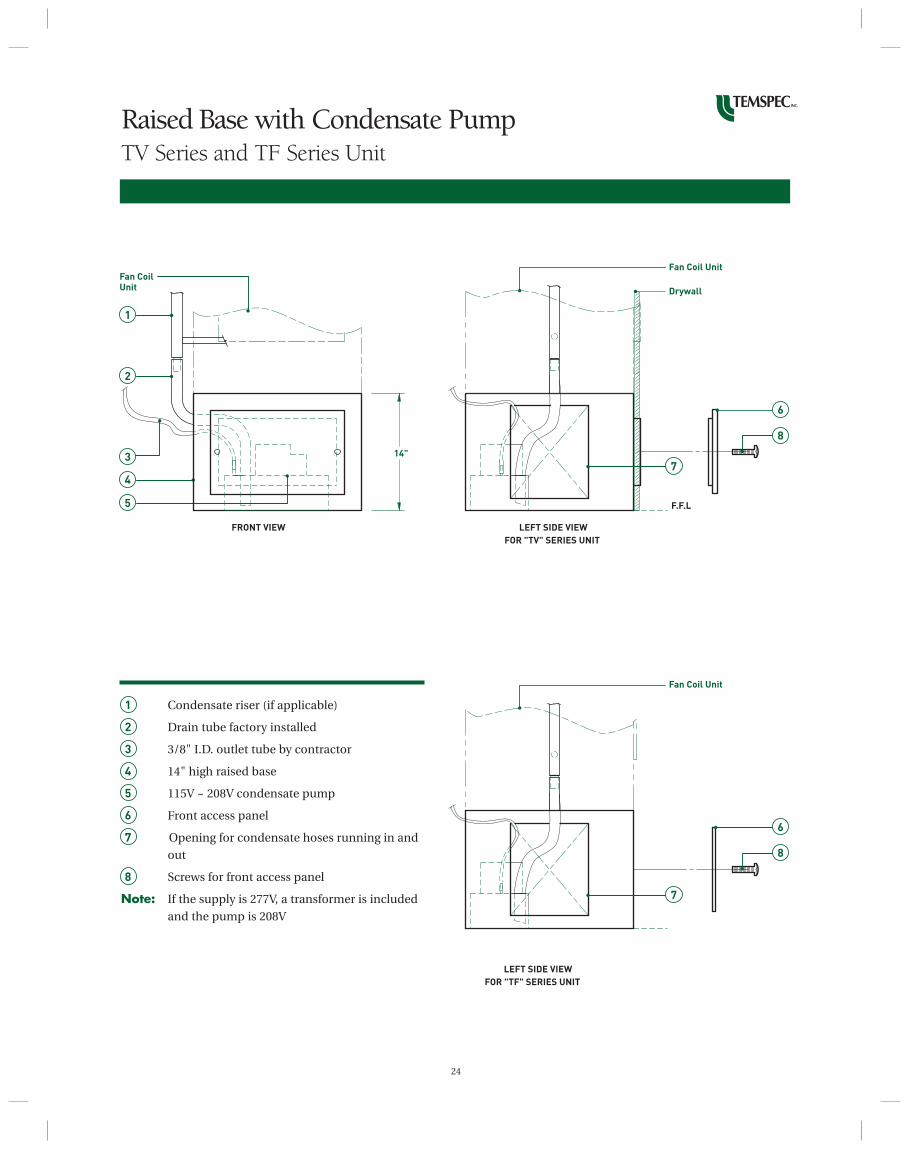
Raised Base with Condensate PumpTV Series and TF Series Unit
14"
Fan Coil Unit
FRONT VIEW
1
2
4
5
3
1 Condensate riser (if applicable)
2 Drain tube factory installed
3 3/8" I.D. outlet tube by contractor
4 14" high raised base
5 115V ~ 208V condensate pump
6 Front access panel
7 Opening for condensate hoses running in and
out
8 Screws for front access panel
Note: If the supply is 277V, a transformer is included
and the pump is 208V
Fan Coil Unit
LEFT SIDE VIEW
FOR "TV" SERIES UNIT
F.F.L
Drywall
7
6
8
LEFT SIDE VIEW
FOR "TF" SERIES UNIT
7
Fan Coil Unit
6
8
25
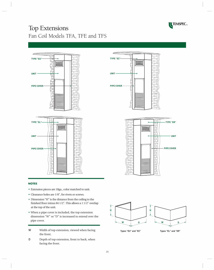
Top Extensions Fan Coil Models TFA, TFE and TFS
TYPE "EU"
TYPE "EL"
UNIT
UNIT
PIPE COVER
PIPE COVER
• Extension pieces are 18ga., color matched to unit.
• Clearance holes are 1/8", for rivets or screws.
• Dimension “H” is the distance from the ceiling to the fi nished fl oor minus 84 1/2". This allows a 1 1/2" overlap
at the top of the unit.
• When a pipe cover is included, the top extension
dimension “W” or “D” is increased to extend over the
pipe cover.
W Width of top extension, viewed when facing
the front.
D Depth of top extension, front to back, when
facing the front.
TYPE "EC"
TYPE "ER"
UNIT
UNIT
PIPE COVER
PIPE COVER
HH
DW DW
Types "EL" and "ER"Types "EU" and "EC"
NOTES
26
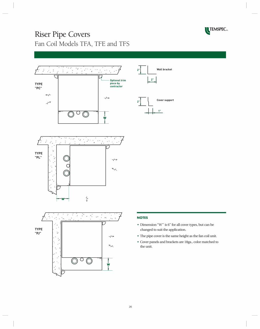
Riser Pipe CoversFan Coil Models TFA, TFE and TFS
Optional trim piece by contractor
w
w
TYPE
"PC"
TYPE
"PL"
TYPE
"PJ"
w
NOTES
• Dimension “W” is 6" for all cover types, but can be
changed to suit the application.
• The pipe cover is the same height as the fan coil unit.
• Cover panels and brackets are 18ga., color matched to the unit.
2"
2"
2"
1"
Wall bracket
Cover support

UNIT VENTILATORS WITH SELF-CONTAINED AIR CONDITIONING
VHC and VLC SERIES
All units have 100% economizer cooling and are available in an upfl ow draw through confi guration for ducted supply air systems or upfl ow blow through for non-ducted units.
Cooling capacities:Self contained DX2 through 5 tons
VUD 1200
Cooling capacities:Split system DX2.0, 2.5, 3.0 tons
Chilled water (2 or 4 pipe)Up to 3.5 tons
UNIT VENTILATORS WITH CHILLED WATER COOLING
All units have 100% economizer cooling and are available in an upfl ow draw through confi guration for ducted supply air systems or upfl ow blow through for non-ducted units. The VDF 1200 unit has a down fl ow option for supply air distribution in a plenum behind casework such as bookshelves or using baseboard level duct.
The HCD 1200 and HCD 1600 units are installed hori-zontally above the ceiling tile. Heating is by hot water, steam or electric coil. Cooling is by a chilled water coil or split system DX coil.
VUD 1600
Cooling capacities:Split system DX4.0 and 5.0 tons
Chilled water (2 or 4 pipe)Up to 5 tons
RESIDENTIAL THERMOSTATHoneywell T6575/8575 Series
HOTEL THERMOSTAT
HotelTech LT Series
• Other thermostat types are available for specifi c applications. Please call the factory for options.
• The Honeywell T6575/8575 and HotelTech LT series thermostats cycle a two position control valve. If modulating or fl oating point valve actuators, or face and bypass damper control, are a requirement a thermostat with analog heat/cool outputs must be used. Chilled water valve modulation (0-10Vdc) is not recommended in humid climates.
GENERAL NOTES PERTAINING TO FAN COIL THERMOSTATS
• The Temspec “TF” series fan coil with exposed fi nished cabinet should be specifi ed with a remote thermostat or with a return air sensor. The T8575D thermostat has a return air sensor option. When a unit mounted thermostat is used, there is a risk of heat pick up from the fan coil cabinet by the thermostat sensor which is within the thermostat casing.
• Unit mounted thermostats can be specifi ed with a quick connect plug.
FAN COIL THERMOSTATS
OTHER TEMSPEC HVAC PRODUCTS
brian
Oval