Lesson Sequence: S4A (Scratch for Arduino) -...
13
Lesson Sequence: S4A (Scratch for Arduino) Rationale: STE(A)M education (STEM with the added ‘Arts’ element) brings together strands of curriculum with a logical integration. The inclusion of CODING in STE(A)M curriculum is a time- sensitive and urgent initiative as technological change underpins growing skills and concepts needed for learners of the 21 st century. The direction of this series of lessons with suggested project –based activities attempts to meet three critical needs: Availability – easy access to apparatus for children to design, build and test project ideas in real time Affordability – while much commercial apparatus is available for school use, it tends to have a high per student cost that excludes many learners form essential skill development. A LEGO Mindstorm kit to service the needs of 4 learners exceeds $300. With more functionality and a price ~$20, the Adruino interface puts more capability into more student hands. Environmental differences quickly show the raw experiential nature of design and connectivity that commercial approaches conceal in plastic containers (like programmable brick in a LEGO kit). Wire connectors, LEDs and switches are only some of the components that have to be properly arranged following a design process. Learner Prerequisites: Science: Basic Electricity / circuits Scratch Fundamentals: You can find introductory tutorials composed by many teachers in the Scratch community o Andreas Gramm – March 2012 http://andreasgramm.de/projects/S4A%20HowTo%20- %20A.%20Gramm.pdf Steps to operation once the hardware is connected:
-
Upload
vuongduong -
Category
Documents
-
view
230 -
download
0
Transcript of Lesson Sequence: S4A (Scratch for Arduino) -...

Lesson Sequence: S4A (Scratch for Arduino)
Rationale: STE(A)M education (STEM with the added ‘Arts’ element) brings together strands of
curriculum with a logical integration. The inclusion of CODING in STE(A)M curriculum is a time-
sensitive and urgent initiative as technological change underpins growing skills and concepts needed
for learners of the 21st century. The direction of this series of lessons with suggested project –based
activities attempts to meet three critical needs:
Availability – easy access to apparatus for children to design, build and test project
ideas in real time
Affordability – while much commercial apparatus is available for school use, it tends to
have a high per student cost that excludes many learners form essential skill
development. A LEGO Mindstorm kit to service the needs of 4 learners exceeds $300.
With more functionality and a price ~$20, the Adruino interface puts more capability
into more student hands.
Environmental differences quickly show the raw experiential nature of design and
connectivity that commercial approaches conceal in plastic containers (like
programmable brick in a LEGO kit). Wire connectors, LEDs and switches are only some
of the components that have to be properly arranged following a design process.
Learner Prerequisites:
Science: Basic Electricity / circuits
Scratch Fundamentals: You can find introductory tutorials composed by many teachers in the
Scratch community
o Andreas Gramm – March 2012 http://andreasgramm.de/projects/S4A%20HowTo%20-
%20A.%20Gramm.pdf
Steps to operation once the hardware is connected:

o Start Arduino software so that computer ‘connects’ to the microcontroller Software is
available at <https://www.arduino.cc/> if needed.
o Load the Arduino script <S4A Firmware16> so that Scratch can communicate with the
microcontroller. It’s available at the same web location <https://www.arduino.cc/> and
<http://s4a.cat/>
o You are now ready to experiment.
To keep in mind: o Projects have more than 1 solution both in the hardware design and/or software
program. o Knowing the common connection strips on a breadboard is essential to circuit design.
(We tried a classroom chart for this.) o What is shown as a sample pattern, can express in many different positions on
Breadboard … The skill to be able to ‘Follow the path of the circuit’ is essential. o The LED looks so simple, yet, many learners, get the polarity backwards. When held up
to the light, ‘the smaller section connected to the longer leg is the anode’. o Learning to ‘Debug’ (the art of uncovering design faults ) both hardware and software
in a new must-have skill for learners. Having tenacity to resolve a problem is a mindset worth pursuing.
o Having a classroom model, as a physical reference, showing basic set-up seems to function smoothly. Include the USB cable (and optional power supply, if using more ‘power hungry’ devices like motors)
The sequence to startup should be displayed for reference. o Connect all devices. o Start the Arduino software. o Upload the S4AFirmware to Arduino memory. o Start ‘Scratch for Arduino’ or ‘Snap for Arduino’ software. (see Appendix if needed to
locate these web resource pages) You may wish to fasten Arduino boards and breadboards to a small piece of plastic. (see
below) This seems to keep centres more organized in the rigor of typical work sessions.
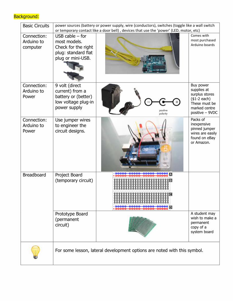
Background:
Basic Circuits power sources (battery or power supply, wire (conductors), switches (toggle like a wall switch or temporary contact like a door bell) , devices that use the ‘power’ (LED, motor, etc)
Connection: Arduino to computer
USB cable – for most models. Check for the right plug: standard flat plug or mini-USB.
Comes with most purchased Arduino boards
Connection: Arduino to Power
9 volt (direct current) from a battery or (better) low voltage plug-in power supply
Buy power supplies at surplus stores ($1-2 each)
These must be marked centre positive – 9VDC
Connection: Arduino to Power
Use jumper wires to engineer the circuit designs.
Packs of inexpensive pinned jumper wires are easily
found on eBay or Amazon.
Breadboard Project Board (temporary circuit)
Prototype Board (permanent circuit)
A student may wish to make a permanent copy of a
system board
For some lesson, lateral development options are noted with this symbol.
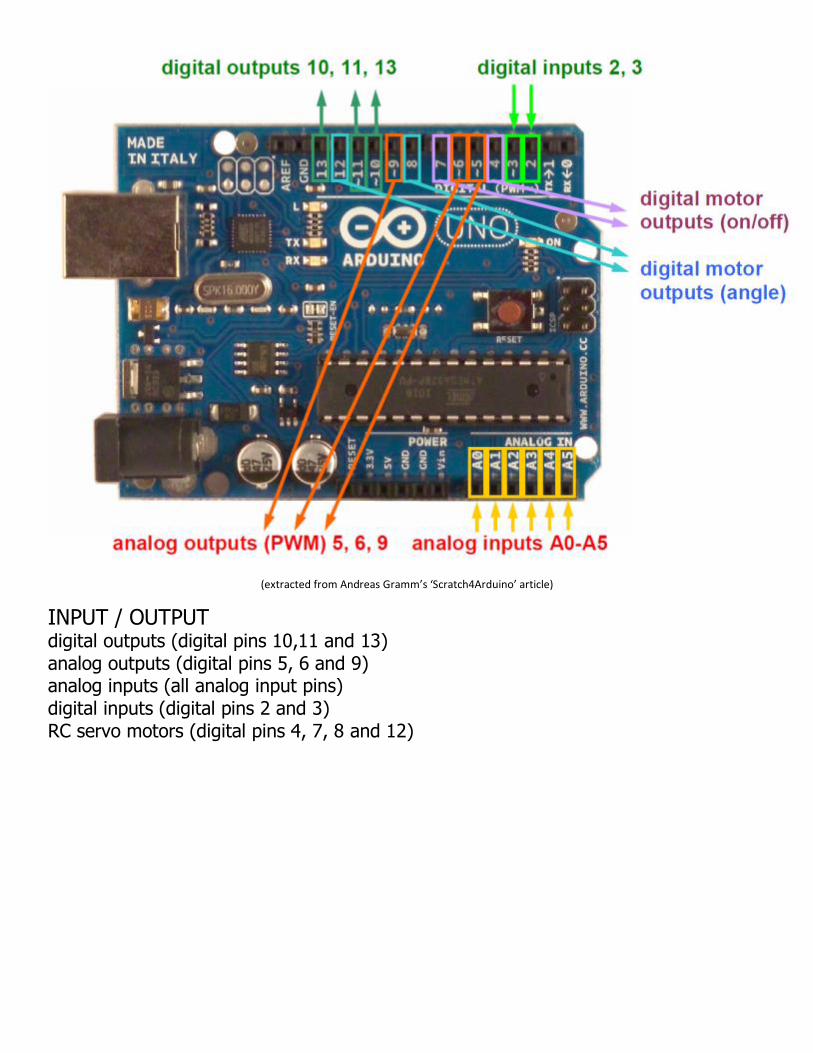
(extracted from Andreas Gramm’s ‘Scratch4Arduino’ article)
INPUT / OUTPUT digital outputs (digital pins 10,11 and 13) analog outputs (digital pins 5, 6 and 9) analog inputs (all analog input pins) digital inputs (digital pins 2 and 3) RC servo motors (digital pins 4, 7, 8 and 12)

Project 1: In this first set of tasks, we’ll program <Output> from the Arduino microcontroller that
acts on commands you design in the software <Snap 4 Arduino>. While this output can vary from
lighting sources to turning motors, we’ll start with the LED.
In this next series of tasks, we’ll play with some of these
outputs, paying attention to setup and programming
needed.
LEDs work well here as they have low power
requirements. Keep in mind that a small device called a
resistor will be used in the power circuit to protect the
LEDs from burnout. (Note the colour bands on the
resistor. These indicate the amount of resistance. A
simple 1K (1000 ohm) resistor is often adequate for our purposes.
Connect the ‘+’ positive leg (Anode) to the 5 volt lines on your breadboard. You can determine this
leg as it’s a bit longer than the negative leg (Cathode). As well, when you hold the LED up to the
light, it’s the smaller of the two elements that you see inside.
Project 1A: LED blinks 5 times at 1 second interval
If the output from Digital 13 wasn’t available, duplicate this task in a different way.

Project 1B: 2 LEDs blink together 7 times at 1 second interval
Project 1C: 2 LEDs blink in an alternate pattern 6 times at 2 second interval
You have to engineer this task on your own. Determine what hardware you’d like to use, then
program (and debug if necessary) the following task. Two LED (colour doesn’t matter) blink
alternatively every two seconds.
Project 1D: 3 LEDs (1 each of red / yellow / green) operate like a traffic control system
For this task, we’ll add to ‘costumes’ so that the screen shows the same
display as the 3 colours of LEDs.

Project 1E: Model Traffic Light System
Build a model of a traffic light control system. It will show:
2 light standards with 3 LEDs of appropriate colours controlling traffic flow in a safe fashion
The 3 LEDs will have a common resistor to control electrical flow to the 3 cathodes
An advanced design will have a 4th LED that operates similar to a walk/don’t walk function
Share the rubric (appendix) with learners prior to design of the system
Project 1F: Digital Numeric Display – Blending Digital and Analogue Output

There are few consumer electronic products that don’t utilize a digital segment display. Essentially,
seven LEDs are arranged to make numbers (and letters with a few more LEDs). We just need to
determine which ones to turn on or off to make the desired display. Most devices have 5 pins on
either side, of which the middle pins #3 and 8, are common (only 1 needs to be connected).
Note: These devices may be common cathode (-) or
common anode (+). The diagram shows the more
common ‘common cathode.
7 LEDs are needed to make the ‘8’ and the round
smaller LED makes the decimal point. Note how these
are labelled A-H. Make a chart to determine the
combinations needed to display digits 0 to 9. You’ll need
this to set the digital and analogue lines. With digital
lines, these are selected as either ‘ON’ or ‘OFF’ but the
Analogue lines are turned ‘ON’ using the value 255 and
‘OFF’ using the value 0.
Project 2: In Project 1, we programmed <Output> from the Arduino microcontroller acting on
commands you designed in the software <Snap 4 Arduino>. The power of the microcontroller lies in
its interactive capabilities – responding to outside influences outside the computer system? … a
switch is turned on … a light source is detected and becomes brighter ….. a temperature changes ….
By having the ability to check the ‘electrical’ status of an input device (immediate condition …. like a
switch turned on or off) can then be used to change the output (lights, motors, etc.) to meet your
design needs.
In this next series of tasks, we’ll play with some of these inputs, paying attention to the mechanical
setup and programming needed.
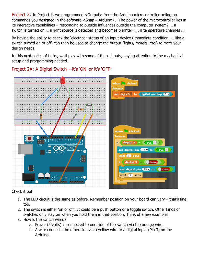
Project 2A: A Digital Switch – it’s ‘ON’ or it’s ‘OFF’
Check it out:
1. The LED circuit is the same as before. Remember position on your board can vary – that’s fine
too.
2. The switch is either ‘on or off’. It could be a push button or a toggle switch. Other kinds of
switches only stay on when you hold them in that position. Think of a few examples.
3. How is the switch wired?
a. Power (5 volts) is connected to one side of the switch via the orange wire.
b. A wire connects the other side via a yellow wire to a digital input (Pin 3) on the
Arduino.
c. Here’s a twist though … Notice a 10K resistor (10 000 ohm) attached to that switch,
which in turn is connected to the <Ground>. Its presence is a bit more complicated,
but in a nutshell, it helps the microcontroller stabilize its sensitive inputs for a ‘solid’
reading.
Here’s some sample code to try. Again, there are many variations that will also work so feel free to
experiment.
Note the program seems to have two parts. <Scratch for Arduino> and <Snap for Arduino> both
allow parallel operations to take place. In this case, the computer is constantly checking the variable
<digital 3> to see IF the switch is ‘ON’ or ‘OFF’. The second parts responds with one of two
possibilities that control whether to turn the LED on or turn it off.
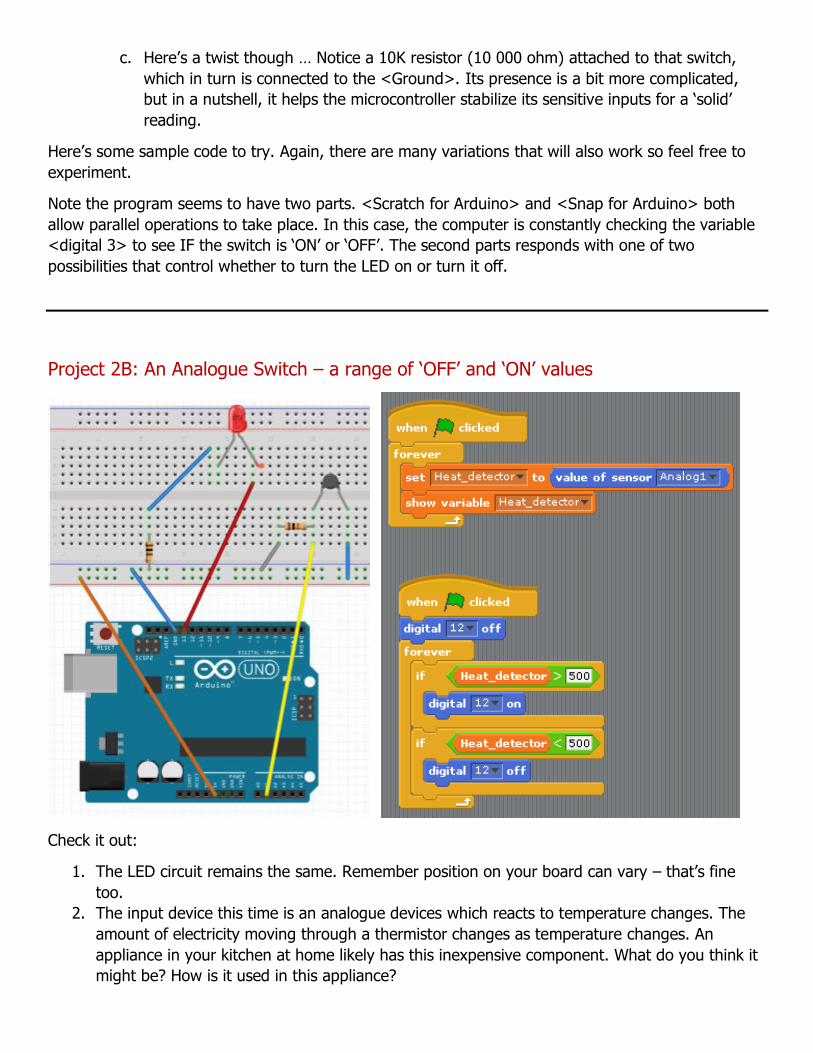
Project 2B: An Analogue Switch – a range of ‘OFF’ and ‘ON’ values
Check it out:
1. The LED circuit remains the same. Remember position on your board can vary – that’s fine
too.
2. The input device this time is an analogue devices which reacts to temperature changes. The
amount of electricity moving through a thermistor changes as temperature changes. An
appliance in your kitchen at home likely has this inexpensive component. What do you think it
might be? How is it used in this appliance?
3. How is the thermistor wired?
a. Power (5 volts) is connected to one side via the orange and blue wire path.
b. A wire connects the other side via a yellow wire to an analogue input (A1) on the
Arduino. You can change this input location; just be sure to adjust your code as
required.
c. That 10K resistor (10 000 ohm – brown black orange) is attached to the thermistor,
which in turn is connected to the <Ground>. Its presence is a bit more complicated but
in a nutshell, it helps the microcontroller stabilize its sensitive inputs for a ‘solid’
reading.
d. NOTE: this resistor may vary depending on the thermistor you use. Since I used a 10K
thermistor, I matched the resistor with the same value.
Here’s some sample code to try. Again, there are many variations that will also work so feel free to
experiment.
Note the program seems to have two parts.
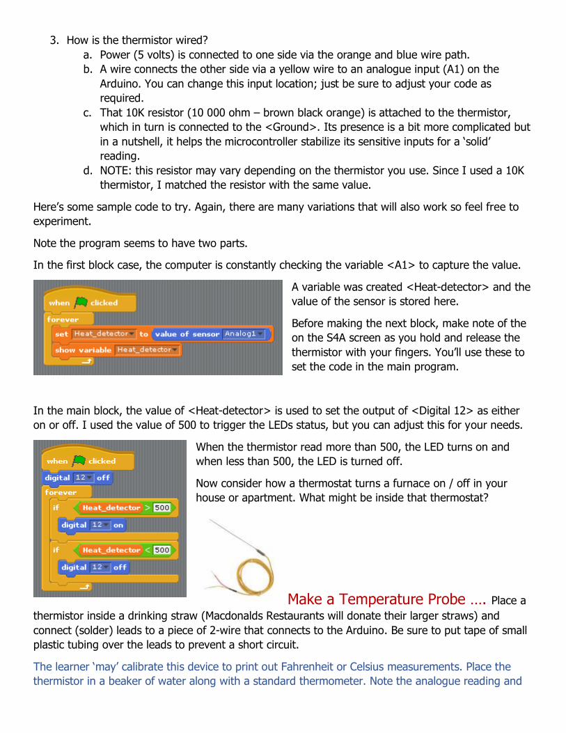
In the first block case, the computer is constantly checking the variable <A1> to capture the value.
A variable was created <Heat-detector> and the
value of the sensor is stored here.
Before making the next block, make note of the
on the S4A screen as you hold and release the
thermistor with your fingers. You’ll use these to
set the code in the main program.
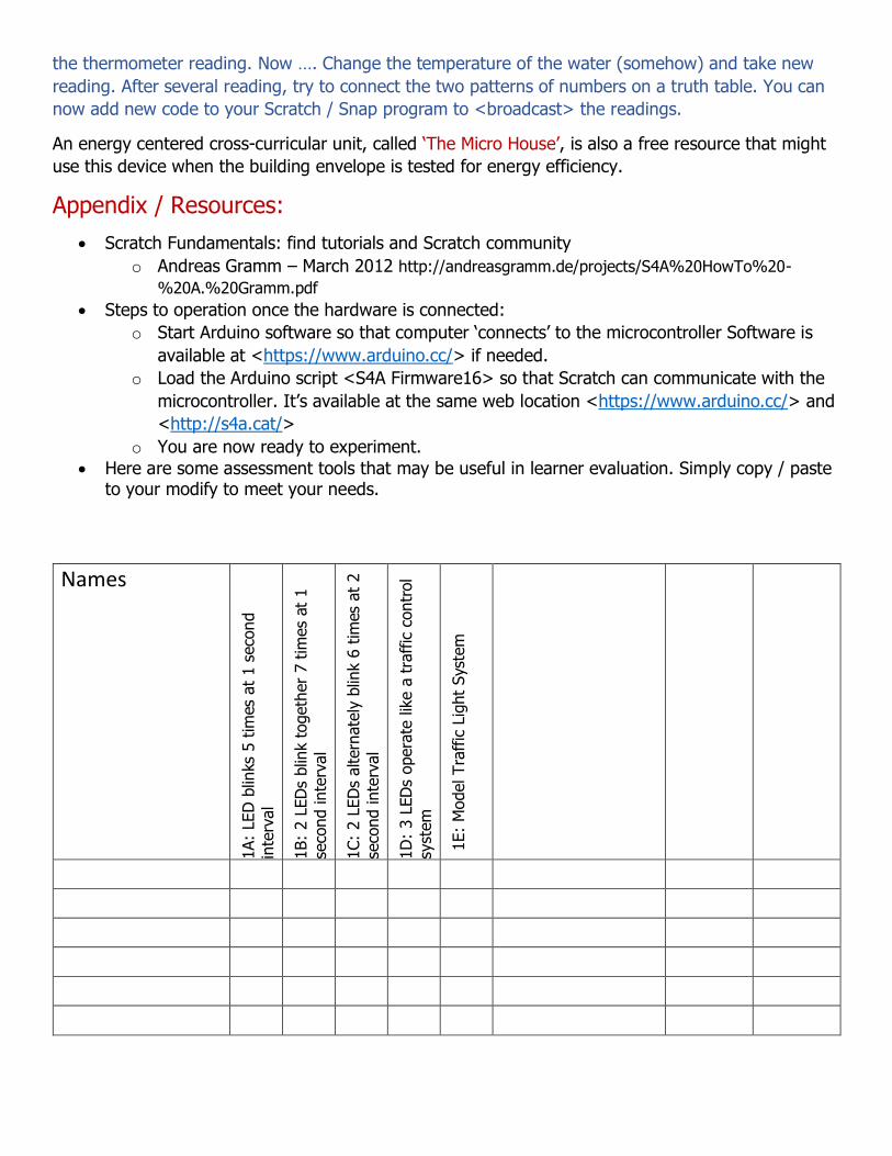
In the main block, the value of <Heat-detector> is used to set the output of <Digital 12> as either
on or off. I used the value of 500 to trigger the LEDs status, but you can adjust this for your needs.
When the thermistor read more than 500, the LED turns on and
when less than 500, the LED is turned off.
Now consider how a thermostat turns a furnace on / off in your
house or apartment. What might be inside that thermostat?
Make a Temperature Probe …. Place a
thermistor inside a drinking straw (Macdonalds Restaurants will donate their larger straws) and
connect (solder) leads to a piece of 2-wire that connects to the Arduino. Be sure to put tape of small
plastic tubing over the leads to prevent a short circuit.
The learner ‘may’ calibrate this device to print out Fahrenheit or Celsius measurements. Place the
thermistor in a beaker of water along with a standard thermometer. Note the analogue reading and
the thermometer reading. Now …. Change the temperature of the water (somehow) and take new
reading. After several reading, try to connect the two patterns of numbers on a truth table. You can
now add new code to your Scratch / Snap program to <broadcast> the readings.
An energy centered cross-curricular unit, called ‘The Micro House’, is also a free resource that might
use this device when the building envelope is tested for energy efficiency.
Appendix / Resources:
Scratch Fundamentals: find tutorials and Scratch community
o Andreas Gramm – March 2012 http://andreasgramm.de/projects/S4A%20HowTo%20-
%20A.%20Gramm.pdf
Steps to operation once the hardware is connected:
o Start Arduino software so that computer ‘connects’ to the microcontroller Software is
available at <https://www.arduino.cc/> if needed.
o Load the Arduino script <S4A Firmware16> so that Scratch can communicate with the
microcontroller. It’s available at the same web location <https://www.arduino.cc/> and
<http://s4a.cat/>
o You are now ready to experiment.
Here are some assessment tools that may be useful in learner evaluation. Simply copy / paste to your modify to meet your needs.
Names
1A:
LED
blin
ks 5
tim
es
at
1 s
eco
nd
inte
rval
1B:
2 L
ED
s blin
k to
geth
er
7 t
imes
at
1
seco
nd inte
rval
1C:
2 L
ED
s altern
ate
ly b
link 6
tim
es
at
2
seco
nd inte
rval
1D
: 3 L
ED
s opera
te lik
e a
tra
ffic
contr
ol
syst
em
1E:
Model Tra
ffic
Lig
ht
Sys
tem

Project 1E: Model Traffic Light System
Rubric Requirement 1 The system does not function in a fashion that is safe to both motorists and
pedestrians
2 The opposing main light standards operates properly to control traffic flow with appropriate time-controlled visual cues.
3 The opposing main light standards operates properly to control traffic flow with appropriate time-controlled visual cues. A ‘Walk / Don’t Walk’ signal aids in safely of pedestrian crossing.
4 The opposing main light standards operates properly to control traffic flow with appropriate time-controlled visual cues. A ‘Walk / Don’t Walk’ signal aids in safely of pedestrian crossing. The system senses the presence of a car (model) on its secondary street to start the light sequence; else, main street flow continues unabated.