Lesson 21 Linear and Geometric Tolerances
34
Linear and Geometric Tolerances ENR 1103-Lesson 21
Transcript of Lesson 21 Linear and Geometric Tolerances

Linear and Geometric TolerancesENR 1103-Lesson 21

Learning Objectives• Describe the purpose of tolerances in manufacturing
• Apply linear and geometric tolerances to engineering drawings

Historical Background
• Jean-Baptiste Vaquette de Gribeauval developed system of interchangeability to build more accurate cannons
• Honoré Blanc applied this concept on smaller weapons, such as muskets
• Thomas Jefferson tried to get him to come to America, but he declined
• George Washington awarded contract to Eli Whitney in 1798 for 12,000 muskets
• Facilitated industrial revolution and the assembly line

Introduction
• Features without any error are impossible to manufacture.
• If a hole has a design diameter of one inch, how close to one inch would it have to be to be considered acceptable?
• Tolerances contribute to the expense of a part. The greater the accuracy (smaller tolerance) the higher the cost of manufacturing.

General Idea of Tolerance
• The dictionary defines tolerance as:• tol·er·ance: n. 2.a. Leeway for variation from a standard. b. The permissible deviation from a specified
value of a structural dimension, often expressed as a percent.
• Paraphrased to:
“Tolerance is how accepting of errors you are”.

Tolerances in Design• The term tolerance refers to the permissible level of error that a machinist is allowed on a
specific dimension.
• It can be understood as a range of acceptable values for a particular dimension.
• This class is not trying to teach the design aspect of tolerance. We will be interested in applying a given tolerance to a part, not in determining the “best” tolerance.
• Various industries (aerospace, electronics, automotive, etc.) set their own tolerances.

Types of Tolerances
General General Tolerances apply to all dimensions on a drawing.
LinearLinear Tolerances refer to specific features that require more accuracy than general tolerances
provide.
Geometric Geometric Tolerances are concerned with a feature’s shape or profile, not its size or dimensions.

General Tolerance• Apply to all dimensions on a drawing.
• Often found in the title block of all drawings intended for manufacturing or as a general note.
• Normally given in bilateral form, defining a symmetric limit above and below a dimension.
General

Linear Tolerance• It is an overriding tolerance used when a specific feature requires greater accuracy than
the one expressed by the general tolerance.
Linear
Limit Form Unilateral Form Bilateral Form
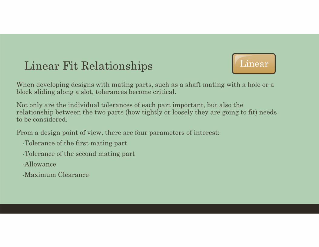
Linear Fit Relationships• When developing designs with mating parts, such as a shaft mating with a hole or a
block sliding along a slot, tolerances become critical.
• Not only are the individual tolerances of each part important, but also the relationship between the two parts (how tightly or loosely they are going to fit) needs to be considered.
• From a design point of view, there are four parameters of interest:• -Tolerance of the first mating part• -Tolerance of the second mating part• -Allowance• -Maximum Clearance
Linear

Design Considerations
• The assembly shown will be used as an example to illustrate these concepts, but the terms can be applied to any two mating parts.
• In this design, the two components fit together with the stud (shaft) from the top piece mating with the hole in the bottom piece.
Linear

Tolerances of Parts
• Hole Tolerance (Bottom Part)• -The difference between the diameters of the largest and smallest possible holes• -Determines the cost of manufacturing the hole• -Does not consider the Shaft at all
• Shaft Tolerance (Top Part)• -The difference between the diameters of the largest and smallest possible shafts• -Determines the cost of the shaft• -Does not consider the Hole at all
Linear

Relationship between Parts
• Allowance• -The tightest fit between two mating parts• -Determines how the two parts will interact with one another• -Smallest dia. hole minus largest dia. shaft • -Does not affect the cost of the parts
• Maximum Clearance• -The loosest fit between mating parts• -Determines how the two parts will interact with one another• -Largest dia. hole minus smallest dia. shaft• -Does not affect the cost of the parts
Linear

Formulas for Calculation
• Hole Tolerance = LPH – SPH
• Shaft Tolerance = LPS – SPS
• Allowance = SPH – LPS
• Maximum Clearance = LPH - SPS
LPH=Largest Possible Hole, SPH=Smallest Possible Hole
LPS-Largest Possible Shaft, SPS=Smallest Possible Shaft
Linear

Hole Tol = 2.0018 – 2.0000 = 0.0018
Shaft Tol = 2.0000 – 1.9988 = 0.0012
Al = 2.0000 – 2.0000 = 0
Max Cl = 2.0018 – 1.9988 = 0.0030
LinearExample
Bottom Part Top Part

Interference Fit
Transition Fit
Line Fit
Types of Fits
• A type of fit represents the degree of tightness between two mating parts.
• Linear tolerances can be classified in 4 major categories, based on the interaction between the parts.
Linear
Clearance Fit

Types of Fits• The internal mating part
(shaft) is always smaller than the external mating part (hole). Therefore, the parts will always fit together with room to spare.
• Some designs require parts that do not interfere with each other, such as pistons inside cylinders in an internal combustion engine.
Clearance Fit Linear

Types of Fits• The internal mating part
(shaft) could possibly be smaller or equal to the external mating part (hole).
• Line fits are used in assemblies with stationary parts, but which can be easily assembled and disassembled.
Line Fit Linear
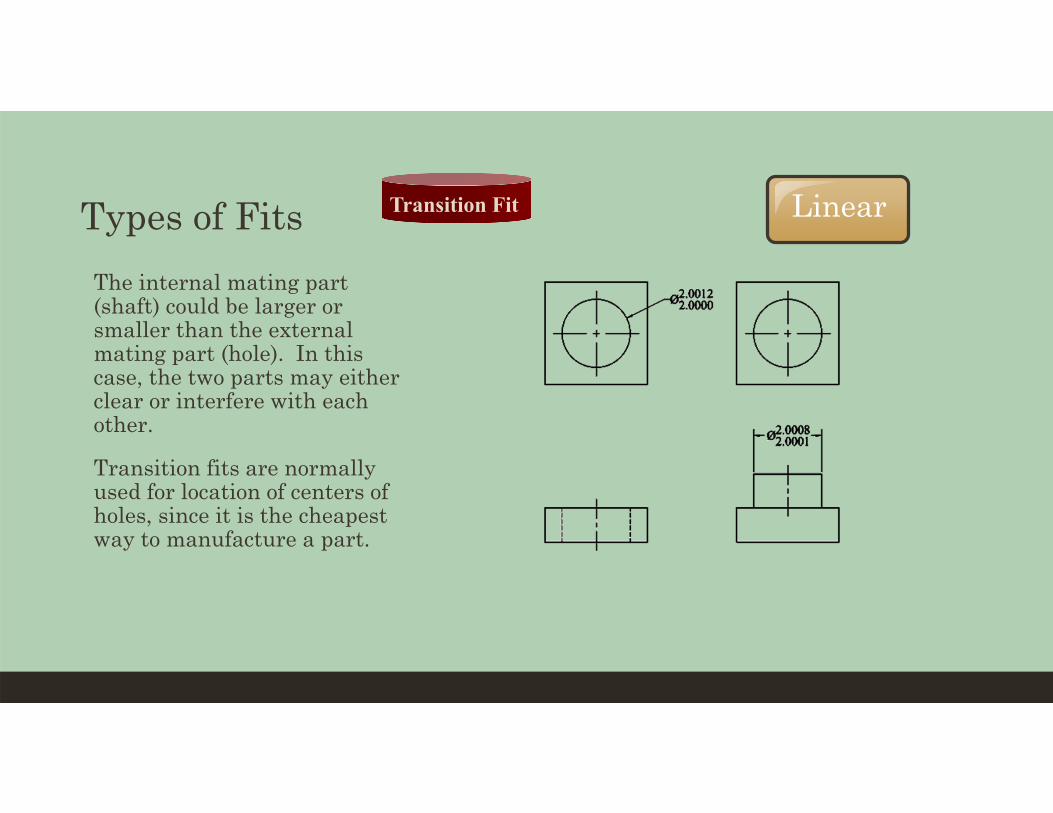
Types of Fits• The internal mating part
(shaft) could be larger or smaller than the external mating part (hole). In this case, the two parts may either clear or interfere with each other.
• Transition fits are normally used for location of centers of holes, since it is the cheapest way to manufacture a part.
Transition Fit Linear

Types of Fits
• Also called “Force Fit”.
• The internal mating part (shaft) will always be larger than the external mating part (hole).
• In order to assemble two parts with an interference fit, it is necessary to apply force to them.
Interference Fit Linear

Standard Fits and Tolerance Tables• In order to make parts interchangeable, tolerance values have been standardized and
recorded in tables for both English and metric systems. This way, a designer does not need to make decisions about specific tolerance values.
• Tolerance tables are used to obtain specific values based on the type of fit and a basic size.
• The four general types of fits are further developed in both the English and metric tolerance tables. There are five types of fits (with different grades or classes) in the English system and ten types in the metric system, depending on its tightness.
Linear

English Fits Linear• ANSI standards list five type of fits.
• The higher the class number, the greater the tolerance

Metric Fits Linear

Tolerance Tables Linear
• Pages 370-376 list the parameters for American tolerance fits.• -Please note that the values listed are in thousandths of an inch!
• Pages 377-381 give the metric tolerance values for the hole basis fits

English Example• Using a basic hole/shaft assembly
and given the following information:• Type of Fit: RC3 (ANSI Running and
Sliding Fit)• Diameter for both shaft and hole: 2.00
inches
• The hole and shaft tolerances can be calculated using the corresponding tolerance table. • The nominal size range 1.97 – 3.15 is
selected because 2.00 inches falls in between these values.
• From the tolerance table, the hole limits are determined to be +1.2 and 0 and the shaft limits are -1.2 and -1.9.
Linear

English Example• Note that these values are in thousandths of an inch, so in reality, the hole limits are
0.0012 and 0, and the shaft limits are -0.0012 and -0.0019.
• These values will be added or subtracted from the target diameter (depending upon the sign) to obtain the proper acceptable range.
Linear

English Example• -Hole limits +1.2, 0 +0.0012, 0
• -Shaft limits -1.2, -1.9 -0.0012, -0.0019
• Therefore:o -Hole Tol = 2.0012 – 2.0000 = 0.0012o -Shaft Tol = 1.9988 – 1.9981 = 0.0007o -Allowance = 2.0000 – 1.9988 = 0.0012o -Max Clearance = 2.0012 – 1.9981 = 0.0031
Linear

Metric Example• Using a basic hole/shaft assembly and given the following information:• -Type of Fit: U7/h6 fit (ANSI Interference Fit)• -Diameter for both shaft and hole: 8 mm
• The hole and shaft diameters are given directly in the corresponding tolerance table.
• Unlike English tolerances, metric tolerances give the exact diameter, not the range.
Linear

Metric Example
• -Hole Limits: 7.978 mm and 7.963 mm.
• -Shaft Limits: 8.000 mm and 7.991 mm.
• Therefore:
o -Hole Tol = 7.978 – 7.963 = 0.015o -Shaft Tol = 8.000 – 7.991 = 0.009o -Allowance = 7.963 – 8.000 = -0.037o -Max Clearance = 7.978 – 7.991 = -0.013
• Note that both the allowance and max clearance are negative, which is expected for a force fit.
Linear
GeometricGeometric Tolerances• Geometric tolerancing is a system that controls the allowed level of error related to
the geometry of features, not the size.
• They are used to define the shape of features: How parallel must two sides be? How concentric must a hole be with a semicircular arc?
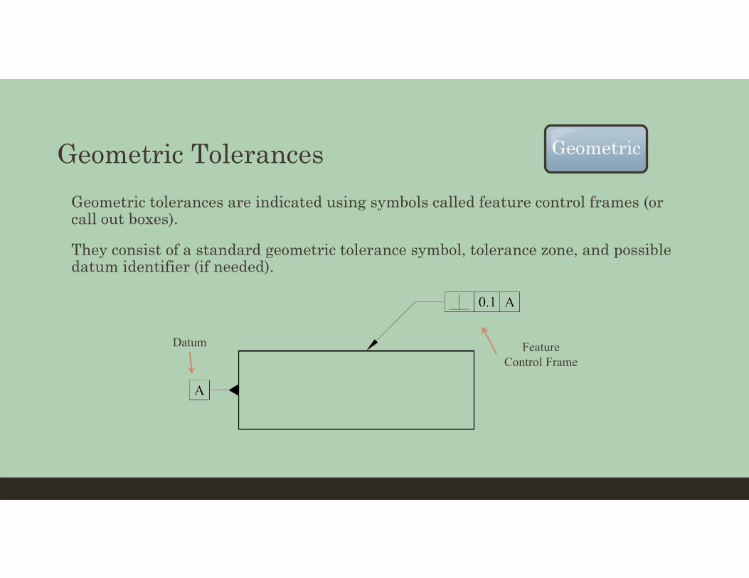
Geometric Tolerances• Geometric tolerances are indicated using symbols called feature control frames (or
call out boxes).
• They consist of a standard geometric tolerance symbol, tolerance zone, and possible datum identifier (if needed).
Feature Control Frame
Datum
Geometric

Categories Geometric

Tolerance Zone Geometric
Explanation
Explanation

Individual Homework (due on Mon, 18 Oct)
• From the Camba text:
• Use pencil and write NEATLY…points will be taken off for lack of neatness• Exercise 1 (page 289)
• Linear tolerance (English)
• Exercise 5 (page 297)• Linear tolerance (Metric)
• Exercise 10 (page 307)• Geometric tolerance