Leonardo Off-Grid · causa della ridotta energia rinnovabile disponibile, sia in caso di potenza...
36
Leonardo Off-Grid 1kW-1500-24 MG Manuale utente User manual IT EN
Transcript of Leonardo Off-Grid · causa della ridotta energia rinnovabile disponibile, sia in caso di potenza...

Leonardo Off-Grid 1kW-1500-24 MG
Manuale utente
User manual
IT
EN

Leonardo Off-Grid 1kW/1500/24 MG
Manuale utente IT
1 REV 6.2 28-03-2018
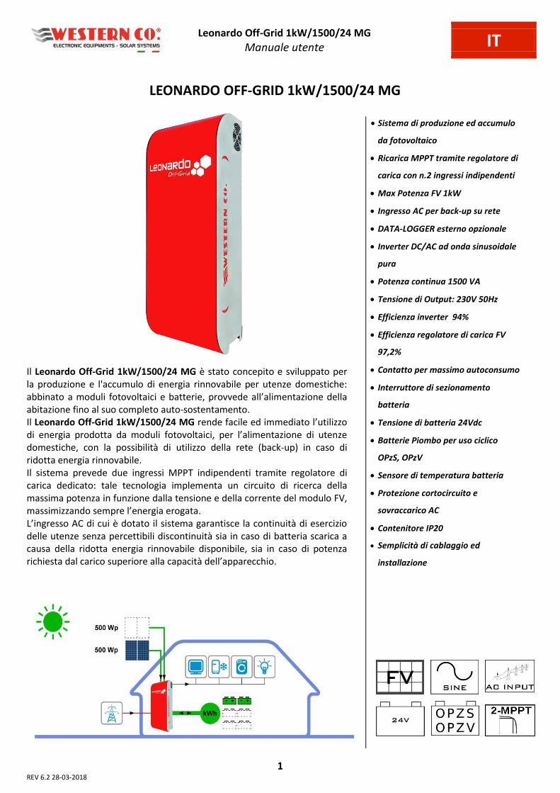
LEONARDO OFF-GRID 1kW/1500/24 MG
Il Leonardo Off-Grid 1kW/1500/24 MG è stato concepito e sviluppato per
la produzione e l'accumulo di energia rinnovabile per utenze domestiche:
abbinato a moduli fotovoltaici e batterie, provvede all’ali e tazio e della abitazione fino al suo completo auto-sostentamento.
Il Leonardo Off-Grid 1kW/1500/24 MG e de fa ile ed i ediato l’utilizzo di e e gia p odotta da oduli fotovoltai i, pe l’ali e tazio e di ute ze domestiche, con la possibilità di utilizzo della rete (back-up) in caso di
ridotta energia rinnovabile.
Il sistema prevede due ingressi MPPT indipendenti tramite regolatore di
carica dedicato: tale tecnologia implementa un circuito di ricerca della
massima potenza in funzione dalla tensione e della corrente del modulo FV,
assi izza do se p e l’e e gia e ogata.
L’i g esso AC di ui è dotato il siste a ga a tis e la o ti uità di ese izio delle utenze senza percettibili discontinuità sia in caso di batteria scarica a
causa della ridotta energia rinnovabile disponibile, sia in caso di potenza
i hiesta dal a i o supe io e alla apa ità dell’appa e hio.
Sistema di produzione ed accumulo
da fotovoltaico
Ricarica MPPT tramite regolatore di
carica con n.2 ingressi indipendenti
Max Potenza FV 1kW
Ingresso AC per back-up su rete
DATA-LOGGER esterno opzionale
Inverter DC/AC ad onda sinusoidale
pura
Potenza continua 1500 VA
Tensione di Output: 230V 50Hz
Efficienza inverter 94%
Efficienza regolatore di carica FV
97,2%
Contatto per massimo autoconsumo
Interruttore di sezionamento
batteria
Tensione di batteria 24Vdc
Batterie Piombo per uso ciclico
OPzS, OPzV
Sensore di temperatura batteria
Protezione cortocircuito e
sovraccarico AC
Contenitore IP20
Semplicità di cablaggio ed
installazione
Leonardo Off-Grid 1kW/1500/24 MG
Manuale utente IT
2
Istruzioni di sicurezza Pericolo di esplosione a causa di scintille
Pericolo di folgorazione
ATTENZIONE: non sollevare oggetti pesanti senza assistenza
Generale
Si consiglia di leggere attentamente questo manuale prima di installare e utilizzare il prodotto.
L’i stallazio e e la a ute zio e del p odotto deve esse e svolta solo da pe so ale ualifi ato. Questo prodotto è progettato e testato in conformità agli standard internazionali. L'apparecchiatura deve essere
utilizzata solo per l'applicazione per cui è stata progettata.
Il prodotto è utilizzato in combinazione con una fonte di energia permanente (batteria). Anche se l'apparecchiatura
è spenta, può verificarsi una tensione elettrica pericolosa ai terminali di ingresso e / o uscita. Spegnere sempre
l’eve tuale ali e tazio e AC, le st i ghe fotovoltai he e s ollega e la atte ia p i a di esegui e la a ute zio e. Il prodotto non contiene parti interne riparabili dall'utente. Non rimuovere il pannello frontale e non mettere in
funzione il prodotto se non sono montati tutti i pannelli.
Non utilizzare mai il prodotto in luoghi in cui potrebbero verificarsi esplosioni di gas o polvere.
Fare riferimento alle specifiche fornite dal produttore della batteria per assicurarsi che sia idonea all'uso con
questo prodotto. Le istruzioni di sicurezza del produttore della batteria devono essere sempre osservate.
Installazione e manutenzione
Questo prodotto è un dispositivo di sicurezza di I classe (fornito con un terminale di terra per motivi di sicurezza). I
suoi terminali di ingresso e / o uscita AC devono essere dotati di messa a terra ininterrotta per motivi di sicurezza.
Un ulteriore punto di messa a terra si trova all'esterno del prodotto. Se si può presumere che la protezione di
messa a terra sia danneggiata, il prodotto dovrebbe essere messo fuori servizio impedendo che possa entrare in
funzione accidentalmente; contattare personale di manutenzione qualificato.
Assicurarsi che i cavi di collegamento siano dotati di fusibili e interruttori automatici. Non sostituire mai un
dispositivo di protezione con un componente di un tipo diverso.
Controllare prima di accendere il dispositivo se la sorgente di tensione disponibile è conforme alle impostazioni di
configurazione del prodotto come descritto nel manuale.
Installare il prodotto in un ambiente che garantisce il range operativo di temperatura. Assicurarsi che non ci siano
sostanze chimiche, parti in plastica, tende o altri tessuti che possono infiammarsi nelle immediate vicinanze
dell'apparecchiatura. Non utilizzarlo mai in un ambiente umido.
Assicurarsi che ci sia sempre sufficiente spazio libero intorno al prodotto per la ventilazione e che le aperture di
ventilazione non siano bloccate.
Proteggere i moduli solari dalla luce incidente durante l'installazione.
Non toccare mai le estremità del cavo non isolate. Utilizzare solo strumenti isolati.
I collegamenti devono sempre essere eseguiti nella sequenza descritta in questo manuale.
L'installatore del prodotto deve fornire un mezzo (es. fermacavi) per impedire che la trazione dei cavi si trasmetta
alle connessioni rovinandole.
Oltre a questo manuale, le operazioni di installazione del sistema devono includere un manuale di manutenzione
della batteria applicabile al tipo di batterie utilizzate.
Trasporto e stoccaggio
Durante lo stoccaggio o il trasporto del prodotto, assicurarsi che l'alimentazione di rete e i cavi della batteria siano
scollegati.
Nessuna responsabilità può essere accettata per danni in transito se l'attrezzatura non viene trasportata nella sua
confezione originale.
Conservare il prodotto in un ambiente asciutto; vedere il range operativo di temperatura per evitare di danneggiare
il prodotto.
Fare riferimento al manuale del produttore della batteria per informazioni su trasporto, conservazione, carica,
ricarica e smaltimento della batteria.
Le indicazioni riportate nel manuale non sostituiscono le norme di sicurezza vigenti nel paese di installazione e le regole
dettate dal comune buonsenso.
Leonardo Off-Grid 1kW/1500/24 MG
Manuale utente IT
3
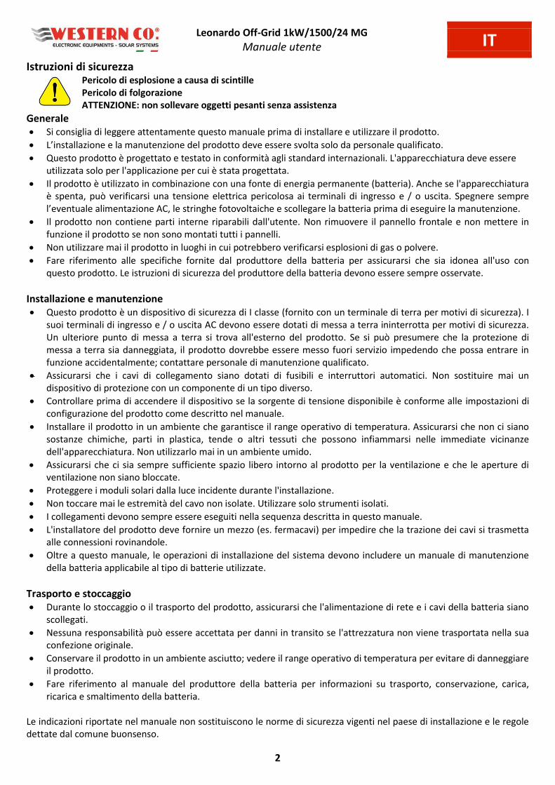
FUNZIONAMENTO DEL LEONARDO OFF-GRID 1kW/1500/24 MG
1. Il Leonardo Off-Grid 1kW/1500/24 MG è progettato per ottenere un risparmio
e e geti o di etto t a ite l’utilizzo di e e gia fotovoltai a ed altre fonti rinnovabili;
2. l'impianto fotovoltaico viene gestito tramite il regolatore di carica interno con n.2
ingressi MPPT indipendenti;
3. l’i ve te fo is e u ispa io di e e gia elett i a o produzione diretta dalle fonti
rinnovabili o da energia immagazzinata in batteria;
4. il Leonardo Off-Grid 1kW/1500/24 MG garantisce una continuità di servizio, qualora
si verifichi un sovraccarico o energia disponibile da fonte rinnovabile insufficiente,
commutando sulla rete AC in ingresso AC-IN;
5. un contatto pulito per massimo autoconsumo permette di attivare carichi utilizzatori
(scaldabagno, pompa di calore, etc...) aumentando la propria quota di energia auto-
consumata;
6. sulla linea delle utenze, AC-OUT, l’e e gia sa à e ogata o la segue te p io ità degli ingressi: autoconsumo diretto dai moduli FV autoconsumo da accumulo in
batteria contatto per massimo autoconsumo soccorso da rete AC-IN;
7. in caso di black-out, tutta l’e e gia i agazzi ata elle atte ie vie e utilizzata pe far fronte alla condizione di emergenza fino allo spegni e to dell’appa e hio he avviene ad una capacità residua del 10-20%.
Fig.1 Pannello frontale
Fig.2 Schema di principio
POTENZA
CONTRATTUALMENTE
IMPEGNATA > 1,5 kW
Leonardo Off-Grid 1kW/1500/24 MG
Manuale utente IT
4
SCHEMA INTERNO
Fig.3 Schema interno
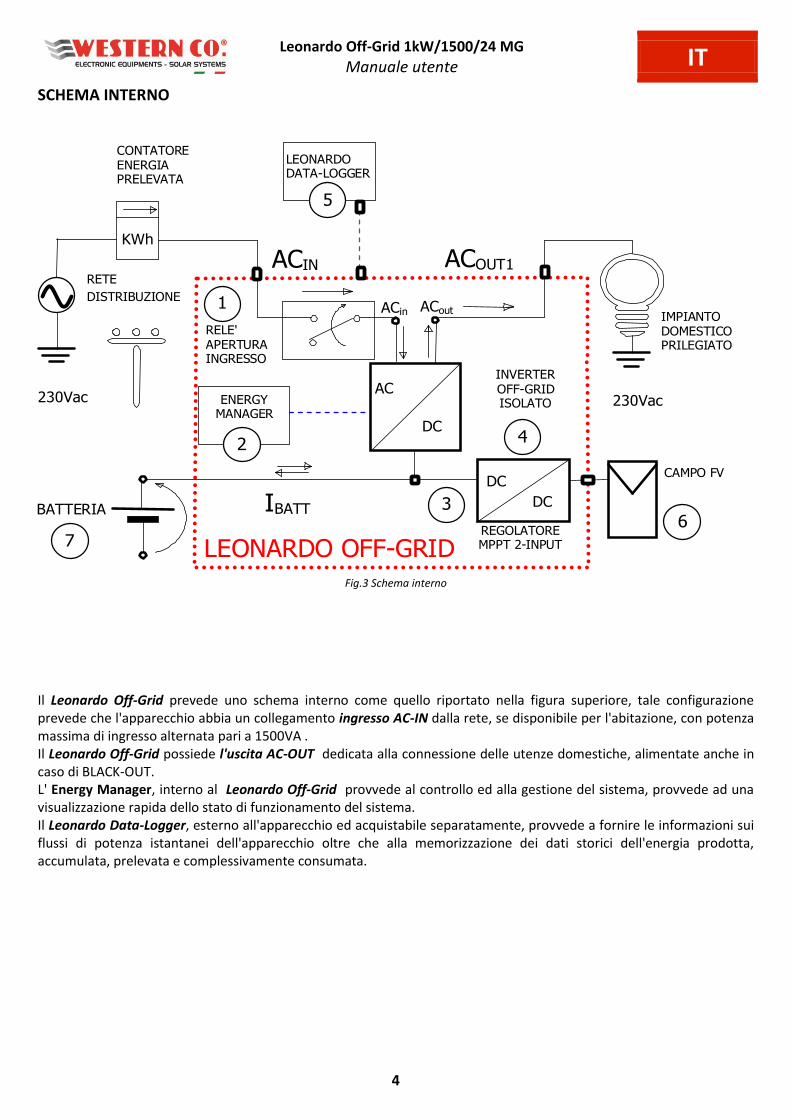
Il Leonardo Off-Grid prevede uno schema interno come quello riportato nella figura superiore, tale configurazione
prevede che l'apparecchio abbia un collegamento ingresso AC-IN dalla rete, se disponibile per l'abitazione, con potenza
massima di ingresso alternata pari a 1500VA .
Il Leonardo Off-Grid possiede l'uscita AC-OUT dedicata alla connessione delle utenze domestiche, alimentate anche in
caso di BLACK-OUT.
L' Energy Manager, interno al Leonardo Off-Grid provvede al controllo ed alla gestione del sistema, provvede ad una
visualizzazione rapida dello stato di funzionamento del sistema.
Il Leonardo Data-Logger, esterno all'apparecchio ed acquistabile separatamente, provvede a fornire le informazioni sui
flussi di potenza istantanei dell'apparecchio oltre che alla memorizzazione dei dati storici dell'energia prodotta,
accumulata, prelevata e complessivamente consumata.
230Vac
RETE
DISTRIBUZIONE
BATTERIA IBATT
ACOUT1
4
LEONARDO
DATA-LOGGER
5
LEONARDO OFF-GRID
RELE'
APERTURA
INGRESSO
INVERTER
OFF-GRID
ISOLATO
AC
3
IMPIANTO
DOMESTICO
PRILEGIATO
1
230Vac
DC
CONTATORE
ENERGIA
PRELEVATA
ACin ACout
ENERGY
MANAGER
2
ACIN
6
DC
DC
REGOLATORE
MPPT 2-INPUT
CAMPO FV
7
KWh
Leonardo Off-Grid 1kW/1500/24 MG
Manuale utente IT
5
SCHEMA DI COLLEGAMENTO
Fig.4 Schema di collegamento
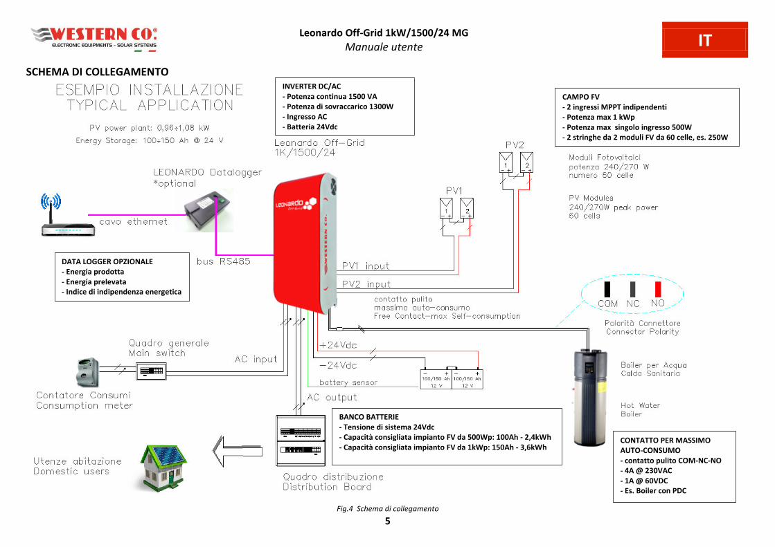
CAMPO FV
- 2 ingressi MPPT indipendenti
- Potenza max 1 kWp
- Potenza max singolo ingresso 500W
- 2 stringhe da 2 moduli FV da 60 celle, es. 250W
INVERTER DC/AC
- Potenza continua 1500 VA
- Potenza di sovraccarico 1300W
- Ingresso AC
- Batteria 24Vdc
BANCO BATTERIE
- Tensione di sistema 24Vdc
- Capacità consigliata impianto FV da 500Wp: 100Ah - 2,4kWh
- Capacità consigliata impianto FV da 1kWp: 150Ah - 3,6kWh
DATA LOGGER OPZIONALE
- Energia prodotta
- Energia prelevata
- Indice di indipendenza energetica
CONTATTO PER MASSIMO
AUTO-CONSUMO
- contatto pulito COM-NC-NO
- 4A @ 230VAC
- 1A @ 60VDC
- Es. Boiler con PDC

Leonardo Off-Grid 1kW/1500/24 MG
Manuale utente IT
6
PROTEZIONI ESTERNE
Protezioni lato Corrente Alternata
Il Leonardo Off-Grid 1kW/1500/24 MG è dotato di una linea di uscita in corrente alternata AC-OUT ed una linea di
ingresso in corrente alternata AC-IN.
Essendo l'apparecchio dotato di collegamento a terra del conduttore NEUTRO - sistema TT, la linea di uscita in corrente
alternata AC-OUT può essere protetta con un interruttore magnetotermico-differenziale di tipo AC, con corrente
nominale In=16A e corrente differenziale Id=0,03A (questo interruttore di solito è già presente nel quadro di
distribuzione dell'abitazione come protezione dai contatti indiretti, con corrente differenziale 30mA).
La linea di ingresso in corrente alternata AC-IN può essere protetta con un interruttore magnetotermico-differenziale di
tipo AC, con corrente nominale In=16A e corrente differenziale Id=0,3A, questo interruttore può essere inserito in un
quadro generale aggiuntivo o, se possibile, nel quadro di distribuzione esistente nell'abitazione.
Protezioni lato Corrente Continua
Il collegamento del banco batterie è effettuato tramite fusibile di protezione sul polo positivo, inoltre l'interruttore di
sezionamento del polo positivo provvede all'attivazione dell'inverter in completa sicurezza.
ATTENZIONE: gli accessori di montaggio del fusibile batteria sono pensati per batterie che hanno morsetti di fissaggio
con bulloni M8, nel caso di diverso diametro del bullone di fissaggio non sarà possibile utilizzare gli accessori a
corredo. In caso di utilizzo di un diverso tipo di fusibile esso deve essere dimensionato correttamente, altrimenti si
potrebbe compromettere il funzionamento del sistema.
Fig.5 Fusibile di Protezione
INTERRUTTORE DI SEZIONAMENTO INVERTER
L'attivazione dell'interruttore di sezionamento del polo positivo di batteria realizza l'accensione dell'inverter in completa
sicurezza.
ATTENZIONE: nella sequenza di ACCENSIONE dell'apparecchio
l'interruttore di sezionamento batteria deve essere attivato ON
per PRIMO, rispetto ai collegamenti FV e corrente alternata AC-
IN e AC-OUT.
Nella sequenza di SPEGNIMENTO dell'apparecchio
l'interruttore di sezionamento batteria deve essere disattivato
OFF per ULTIMO, rispetto ai collegamenti FV e corrente
alternata AC-IN e AC-OUT.
Fig.6 Interruttore di sezionamento inverter
Dado plastico
Occhiello d.10mm
Fusibile 300A
Dado M8 rondellato
Occhiello d.8mm
Grano M8 x 60mm
cavo INVERTER
cavo PARALLELO
BATTERIA
Leonardo Off-Grid 1kW/1500/24 MG
Manuale utente IT
7
SEZIONE REGOLATORI DI CARICA FOTOVOLTAICA
Il Leonardo Off-Grid 1kW/1500/24 MG è dotato di regolatore di carica FV con 2 ingressi MPPT indipendenti: è un
regolatore di carica da moduli fotovoltaici per batterie elettrochimiche al piombo di tipo OPzV o OPzS.
Per il corretto riconoscimento della tensione di batteria eseguito all’a e sio e, di o segue za imposta i parametri di
ricarica appropriati come descritto in Tab.1.
Te sio e di atte ia isu ata all’avvio
20.0V < Vbatt < 32.0V Batteria a 24V Tab.1 Rilevamento Tensione di Sistema
Scelta del modulo fotovoltaico
Nella scelta della configurazione della stringa di moduli da impiegare nel sistema è necessario attenersi strettamente a
quanto indicato nella seguente tabella.
Grazie alla presenza del regolatore di carica con circuito di ricarica con MPPT, è possibile collegare i moduli a due
ingressi indipendenti garantendo così lo sfruttamento ottimale di tutta la potenza.
Tensione nominale batteria Caratteristiche moduli PV
Batteria a 24V OPzS - OPzV,
tensione di carica in fase di
tensione costante (ABSORPTION)
Vch=28,8V alla temperatura di
25°C
Moduli con 60 celle Si mono-cristallino / poli-cristallino per una
potenza tipica di 230 - 270Wp
Collegare minimo 2 moduli in serie per ogni ingresso FV, la potenza
per ogni singolo ingresso richiede un minimo di 450 W fino a un
massimo di 550 W.
Corrente di corto circuito massima: 13A per ogni ingresso.
Tensione a circuito aperto massima: 150V per ogni ingresso. Tab.2 Scelta del Modulo Fotovoltaico
NOTTE
BULK
ABSORPTION
FLOAT
NOTTE
Vfloat
Vch
TAbs.
Fig.7 Curva di carica
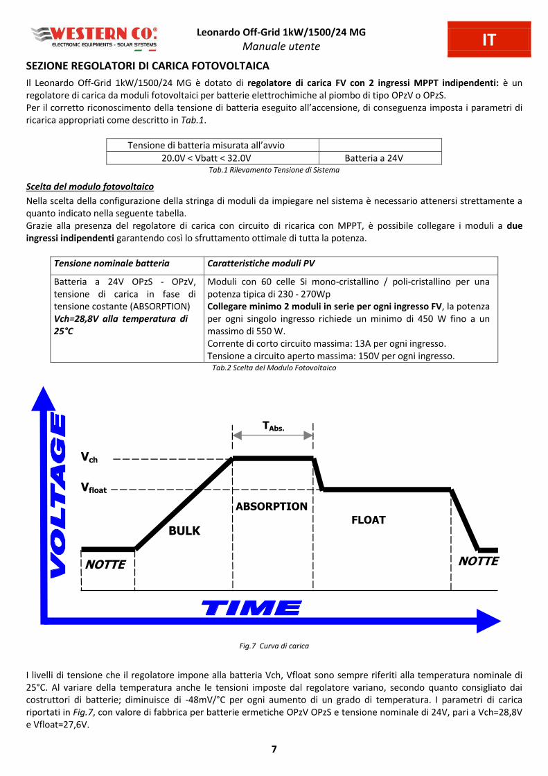
I livelli di tensione che il regolatore impone alla batteria Vch, Vfloat sono sempre riferiti alla temperatura nominale di
25°C. Al variare della temperatura anche le tensioni imposte dal regolatore variano, secondo quanto consigliato dai
costruttori di batterie; diminuisce di -48mV/°C per ogni aumento di un grado di temperatura. I parametri di carica
riportati in Fig.7, con valore di fabbrica per batterie ermetiche OPzV OPzS e tensione nominale di 24V, pari a Vch=28,8V
e Vfloat=27,6V.

Leonardo Off-Grid 1kW/1500/24 MG
Manuale utente IT
8
SEGNALAZIONI ESTERNE
Sul lato laterale del Leonardo Off-Grid 1kW/1500/24 MG sono presenti le seg alazio i di fu zio a e to dell’i ve te : Inverter Mode e Bypass Mode, lo stato di carica della batteria, la potenza assorbita dal carico, lo stato del carica da
fotovoltaico e la presenza della rete AC in ingresso.
Fig.8 Segnalazione Inverter Mode
Nel caso in Fig.8 è possi ile ota e lo stato di fu zio a e to dell’i ve te i odalità Inverter Mode: il carico viene
alimentato dalle fonti rinnovabili, la batteria presenta uno stato di carica con almeno il 75% di carica residua, il carico
assorbe una potenza compresa tra 200W e 1000W, il carica batteria da fotovoltaico è attivo, è presente la rete di
ingresso AC.
Nel caso di mancanza di fonte rinnovabile la batteria raggiunge lo stato di carica residua del 40%, quindi si passa alla
modalità di funzionamento Bypass Mode.
Fig.9 Segnalazione Bypass Mode
Nel caso in Fig.9 i fatti è possi ile ota e lo stato di fu zio a e to dell’i ve te i odalità Bypass Mode: il carico
vie e ali e tato dall’i g esso AC este o, la atte ia p ese ta u o stato di carica con almeno il 40% di carica residua, il
carico assorbe una potenza compresa tra 1000W e 2200W, il carica batteria da fotovoltaico è attivo ed è presente la
rete di ingresso AC.
Protezione da sovraccarico
Quando si verifica un sovraccarico di potenza sul a i o d’us ita se la pote za supera il limite di 1300 W per 1 secondo)
l’i ve te o uta sulla ete AC input, visualizzando lo stato di Bypass Mode. Una volta che la potenza rientra nel limite
di 1200 W per 3 i uti l’i ve te o uta ella odalità Inverter Mode.
ATTENZIONE: per effetto della protezione da sovraccarico e della taglia di inverter Leonardo Off-Grid
1kW/1500/24 MG, il contratto di fornitura di energia elettrica deve prevedere una potenza
contrattualmente impegnata di almeno 1,5kW.

Leonardo Off-Grid 1kW/1500/24 MG
Manuale utente IT
9
LOGICA DI FUNZIONAMENTO
Fig.10 Logica di funzionamento
Tabella Stato di carica e potenza di uscita
Stato di carica SOC livello 4, l'energia
effettivamente stoccata in batteria si trova
in un intervallo compreso tra
75% - 100% della propria capacità nominale
(tensione maggiore di 27,2V).
Potenza di uscita LOAD livello 4, la
potenza elettrica delle utenze in uscita è
superiore al livello di 4000W.
Stato di carica SOC livello 3, l'energia
effettivamente stoccata in batteria si trova
in un intervallo compreso tra
60% - 75% della propria capacità nominale
(tensione maggiore di 24V).
Potenza di uscita LOAD livello 3, la
potenza elettrica delle utenze in uscita è
compresa in un intervallo di
2200W - 4000W.
Stato di carica SOC livello 2, l'energia
effettivamente stoccata in batteria si trova
in un intervallo compreso tra
40% - 60% della propria capacità nominale
(tensione maggiore di 23V).
Potenza di uscita LOAD livello 2, la
potenza elettrica delle utenze in uscita è
compresa in un intervallo di
1000W - 2200W.
Stato di carica SOC livello 1, l'energia
effettivamente stoccata in batteria si trova
in un intervallo compreso tra
30% - 40% della propria capacità nominale
(tensione maggiore di 21V).
Potenza di uscita LOAD livello 1, la
potenza elettrica delle utenze in uscita è
compresa in un intervallo di
200W - 1000W.
Tab.3 Stato di Carica e Potenza di Uscita
Home Consumption Inverter Limitation PV Production Grid Power Battery Power

Leonardo Off-Grid 1kW/1500/24 MG
Manuale utente IT
10
Tabella segnalazione LED STATUS
LED STATUS Led VERDE: normale stato di funzionamento attivo ON.
LED STATUS Led ROSSO n.1 lampeggio ogni 10 Secondi: stato di allarme SOVRA-TEMPERATURA.
LED STATUS Led ROSSO n.2 lampeggi ogni 10 Secondi: stato di allarme LOW-BATTERY.
LED STATUS Led ROSSO n.3 lampeggi ogni 10 Secondi: stato di allarme OVER-LOAD.
Tab.4 Segnalazione LED STATUS
ATTENZIONE: in caso di BLOCCO dell'inverter, nessuna tensione di alimentazione sull'uscita AC-OUT,
causa una delle tre condizioni di anomalia indicate in Tab.4, è necessario un RIAVVIO dell'apparecchio,
attraverso la pressione del tasto di RESET presente alla base dell'apparecchio (Fig. 12).
INSTALLAZIONE E CABLAGGIO
a) Installare il Leonardo Off-Grid 1kW/1500/24 MG in un luogo asciutto ed adeguatamente arieggiato, fissato su di
una superficie non infiammabile e posizionato in modo da lasciare uno spazio privo di ostacoli di almeno 10cm
ell’i to o del dispositivo he e pe ette il aff edda e to pe o vezio e fo zata dell’a ia.
b) Fissare a muro la staffa di supporto (fornita in dotazione) tramite i tasselli e le viti fornite in dotazione;
su essiva e te agga ia e l’i ve te t a ite la piast a ad u i o posta ella pa te supe io e dell’appa e hio. Infine fissare l’i ve te alla pa ete utilizza do i fo i p edisposti ella pa te i fe io e dell’appa e hio. Il tutto come
indicato in Fig.11.
Fig.11 Montaggio a parete
c) Collega e ell’o di e: 1. cavo batteria positivo (vedi collegamento nella sezione Protezioni Lato Corrente Continua);
2. cavo batteria negativo;
3. attivare l'interruttore di sezionamento batteria - posizione ON;
4. collegare i moduli fotovoltaici PV1-PV2 (verificando la polarità di ciascuna coppia di cavi che dovrà essere
ollegata i i g esso all’i ve te ;
PIASTRA AD UNCINO parte
superiore dell’inverter
STAFFA DI SUPPORTO
PIASTRA parte
inferiore dell’inverter

Leonardo Off-Grid 1kW/1500/24 MG
Manuale utente IT
11
5. collegare ingresso AC IN su connessione AC Input tramite connettori AC plug and play tipo RST (se
presente);
6. collegare uscita AC OUT su connessione AC Output tramite connettori AC plug and play tipo RST;
7. posizio a e i fi e l’apposito avo al sensore di temperatura delle batterie in prossimità della stessa, al fine
di un corretto rilevamento.
L’appa e hio vie e dotato di cavo per collegamento batteria di lunghezza 1,5m quindi è assolutamente raccomandato
installare il banco batteria ad una distanza tale da mantenere il cavo originale per il collegamento.
Aumentare la distanza con il banco batterie comporta un aumento della caduta di tensione sul cavo in fase di
funzionamento quindi una errata lettura della tensione di batteria.
La sezione dei cavi batteria è di 25 mm2.
Utilizzare il cavo in dotazione per effettuare il collegamento ai morsetti principali di batteria e nel caso di un banco
batteria costituito da più elementi in serie o in parallelo utilizzare un cavo di sezione minima 50 mm2 per il cablaggio di
ciascun elemento in serie o in parallelo.
In caso di installazione di sistemi trifase o più macchine in parallelo o di banco batterie costituito da molti elementi è
assoluta e te o sigliata l’i stallazio e di u a a a di a e pe il a laggio delle atte ie. Si a o a da l’i stallazio e dell’appa e hio su pa ete solida i posizio e ve ti ale, al fine di assicurare un adeguato
i i olo di a ia, dovuta alla ve tilazio e fo zata dell’appa e hio. Pe tale otivo è i olt e da evita e l’i stallazio e i
luoghi ricchi di polvere e sporco.
Fig.12 Cablaggio
PV INPUT + Numero 2 ingressi positivi Cablaggio plug and play
4-6mm^2 (in fig. controparte maschio)
Uscita Cavi DC Batteria
Lunghezza cavo 1,5 m Sezione 25 mm^2
AC OUTPUT Cablaggio tramite connettori plug
and play a 3 poli - 6mm^2
PV INPUT - Numero 2 ingressi negativi
Cablaggio plug and play 4-6mm^2
(in fig. controparte femmina)
Ingresso sensore di temperatura
Lunghezza cavo 1,5 m
CONTATTO MAX AUTO-CONSUMO Numero 3 Poli del contatto
COM-NERO NC-BIANCO NO-ROSSO
Uscita PLUG NERO DATALOGGER
Uscita PLUG BIANCO SYNC
TASTO RESET INVERTER
AC INPUT Cablaggio tramite connettori
plug and play a 3 poli - 6mm^2

Leonardo Off-Grid 1kW/1500/24 MG-SL
Manuale utente IT
12
AVVIAMENTO E COLLAUDO DELL’IMPIANTO
Appena realizzati i collegamenti come in Fig.12 è necessario procedere avviamento e collaudo del sistema:
1. ve ifi a e l’a e sio e del Leonardo Off-Grid 1kW/1500/24 MG al termine del collegamento dei cavi sui morsetti
della batteria ed attivazione dell'interruttore di sezionamento batteria;
2. verificare la corretta carica di batteria, in caso contrario verificare la corretta installazione del banco batterie;
3. attivare se presente la linea di ingresso AC attraverso le connessioni AC-IN;
4. ve ifi a e l’attivazio e della li ea di us ita AC-OUT, se p ese te u a i o l’i ve te e oga pote za e lo stato è disponibile dalle indicazioni luminose del carico LOAD;
5. in base alle condizioni di carica della batteria, della presenza della rete in ingresso, si può osservare il corretto
funzionamento della logica di funzionamento dell’i ve te , o e da Fig. 10.
EVENTUALI PROBLEMATICHE E SOLUZIONI
Led AC IN spento Verificare la tensione in ingresso e il cablaggio del connettore AC-IN.
Assenza tensione in uscita AC-OUT Verificare il cablaggio del connettore AC-OUT. Ve ifi a e se l’E e gy Ma age presenta entrambi i led BYPASS e INVERTER spenti.
E tra bi i Led Bypass e Inverter spe ti P ovvede e a esetta e l’i ve te esegue do la p o edu a o e da ma uale. Ad i ve te spe to gi a e solo il sezio ato e DC delle atte ie e ve ifi a e l’a e sio e del Led BATTERY e del Led INVERTER. Ve ifi a e l’i teg ità di eve tuali fusi ili DC di p otezio e. Se il p o le a pe a e si o siglia di o tatta e l’assistenza tecnica Western CO.
Led PV CHARGE sempre spento Verificare il cablaggio delle stringhe fotovoltaiche.
Led STATUS spento. Effettuare reset inverter come da manuale.
APPLICAZIONI TRIFASE O PARALLELO CON VERSIONE SLAVE SL
Leonardo Off-Grid 1kW/1500/24 MG, versione Master per applicazioni con ingresso da rete, ha la possibilità di
installazione in impianti di tipo TRIFASE o PARALLELO attraverso l'utilizzo del codice Leonardo Off-Grid 1kW/1500/24
SL, versione SLAVE.
Ogni installazione prevede n.1 inverter di tipo Master e N inverter di tipo Slave a seconda della configurazione.
Ad esempio:
Impianto Trifase tot. 4,5kW:
Fase L1 n.1 Master - Fase L2 n.1 Slave - Fase L3 n.1 Slave
Fig.13 Schema di collegamento BUS di controllo Sy c dell’i pia to trifase , kW
INVERTER MASTER L1
A - Plug Datalogger
B - Plug Sincronismo
INVERTER SLAVE L2
A - Plug Sincronismo
B - Plug Sincronismo
INVERTER SLAVE L3
A - Plug Sincronismo
B - non connesso
CAVO SYNC
Cavo Patch 8 poli
CAVO
DATALOGGER
Cavo Patch
8 poli
CAVO SYNC
Cavo Patch 8 poli

Leonardo Off-Grid 1kW/1500/24 SL
Manuale utente IT
13
Schema Unifilare dell'impianto trifase 4,5kW.
Fig.14 Schema Unifilare dell'impianto trifase 4,5kW

Leonardo Off-Grid 1kW/1500/24 SL
Manuale utente IT
14
Impianto Trifase tot. 9kW:
Fase L1 n.1 Master + n.1 Slave - Fase L2 n.2 Slave - Fase L3 n.2 Slave
Fig.15 Schema di collegamento BUS di controllo Sync dell’i pia to trifase 9 kW
.
Impianto Parallelo tot. 3kW:
Fase L1 n.1 Master + n.1 Slave
Fig.16 Schema di collegamento BUS di controllo Sy c dell’i pia to parallelo kW
INVERTER MASTER L1
A - Plug Datalogger
B - Plug Sincronismo
INVERTER SLAVE L2
A - Plug Sincronismo
B - Plug Sincronismo
INVERTER SLAVE L3
A - Plug Sincronismo
B - Plug Sincronismo
INVERTER SLAVE L1
A - Plug Sincronismo
B - Plug Sincronismo
INVERTER SLAVE L2
A - Plug Sincronismo
B - Plug Sincronismo
INVERTER SLAVE L3
A - Plug Sincronismo
B – non connesso
CAVO SYNC
Cavo Patch 8 poli
CAVO
DATALOGGER
Cavo Patch
8 poli
CAVO SYNC
Cavo Patch 8 poli
CAVO SYNC
Cavo Patch 8 poli
CAVO SYNC
Cavo Patch 8 poli
CAVO SYNC
Cavo Patch 8 poli
CAVO
DATALOGGER
Cavo Patch 8 poli
CAVO SYNC
Cavo Patch 8 poli
INVERTER SLAVE L1
A - Plug Sincronismo
B - non connesso
INVERTER MASTER L1
A - Plug Datalogger
B - Plug Sincronismo
Leonardo Off-Grid 1kW/1500/24
Manuale utente IT
15
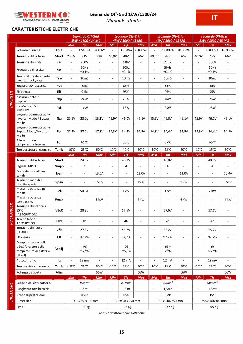
CARATTERISTICHE ELETTRICHE
Leonardo Off-Grid
1kW / 1500 / 24 MG
Leonardo Off-Grid
4kW / 3000 / 48 MG
Leonardo Off-Grid
4kW / 5000 / 48 MG
Leonardo Off-Grid
8kW / 8000 / 48 MG
INV
ER
TE
R
Min Tip Max Min Tip Max Min Tip Max Min Tip Max
Potenza di uscita Pout - 1.500VA 3.000W - 3.000VA 6.000W - 5.000VA 10.000W - 8.000VA 16.000W
Tensione di batteria Vbatt 20,0V 24V 33V 40,0V 48V 66V 40,0V 48V 66V 40,0V 48V 66V
Tensione di uscita Vac - 230V - - 230V - - 230V - - 230V -
Frequenza di uscita Fac - 50Hz
±0,1% - -
50Hz
±0,1% - -
50Hz
±0,1% - -
50Hz
±0,1% -
Tempo di trasferimento
Inverter <> Bypass Tsw - 10mS - - 10mS - - 10mS - - 10mS -
Soglia di sovraccarico Poc - 85% - - 85% - - 85% - - 85% -
Efficienza Eff - 94% - - 95% - - 95% - - 95% -
Assorbimento in
bypass Pbp - <4W - - <5W - - <6W - - <6W -
Autoconsumo in
stand-by Psb - 10W - - 16W - - 25W - - 25W -
Soglia di commutazione
Inverter Mode / Bypass
Mode
Tba 22,9V 23,0V 23,1V 45,9V 46,0V 46,1V 45,9V 46,0V 46,1V 45,9V 46,0V 46,1V
Soglia di commutazione
Bypass Mode/ Inverter
Mode
Tbs 27,1V 27,2V 27,3V 54,3V 54,4V 54,5V 54,3V 54,4V 54,5V 54,3V 54,4V 54,5V
Allarme sovra-
temperatura interna Tot 65°C 65°C 65°C 65°C
Temperatura di esercizio Tamb -10°C 25°C 60°C -10°C 40°C 60°C -10°C 25°C 60°C -10°C 25°C 60°C
PV
CH
AR
GE
R
Min Tip Max Min Tip Max Min Tip Max Min Tip Max
Tensione di batteria Vbatt - 24,0V - - 48,0V - - 48,0V - - 48,0V -
Ingressi MPPT Nmpp - 2 - - 4 - - 4 - - 4 -
Corrente moduli per
canale Ipan - - 13,0A - - 13,0A - - 13,0A - - 26,0A
Tensione moduli a
circuito aperto Vpan - - 150 V - - 150V - - 150V - - 150V
Massima potenza per
canale Pch - 500W - - 1kW - - 1kW - - 2 kW -
Massima potenza
complessiva Pmax - - 1 kW - - 4 kW - - 4 kW - - 8 kW
Tensione di ricarica a
25°C
(ABSORPTION)
VEoC - 28,8V - - 57,6V - - 57,6V - - 57,6V -
Tempo fase di
ABSORPTION Tabs - 4h - - 4h - - 4h - - 4h -
Tensione di riposo
(FLOAT) Vflt - 27,6V - - 55,2V - - 55,2V - - 55,2V -
Efficienza Eff - 97,2% - - 97,2% - - 97,2% - - 97,2% -
Compensazione della
VEoC funzione della
temperatura di batteria
(Tbatt)
Vtadj - -96
mV/°C - -
-96
mV/°C - -
-96m
V/°C - -
-96
mV/°C -
Autoconsumo Iq - 12 mA - - 12 mA - - 12 mA - - 12 mA -
Temperatura di esercizio Tamb -10°C 25°C 60°C -10°C 25°C 60°C -10°C 25°C 60°C -10°C 25°C 60°C
Potenza dissipata Pdiss 66W 66W 66W 66W
EN
CLO
SU
RE
Min Tip Max Min Tip Max Min Tip Max Min Tip Max
Sezione dei cavi batteria -
25mm2 -
-
25mm
2 -
-
35mm
2 -
-
50mm
2 -
Lunghezza cavi batteria - 1,5mt - - 1,5mt - - 1,5mt - - 1,5mt -
Grado di protezione IP20 IP20 IP20 IP20
Dimensioni 315x750x130 mm 395x940x250 mm 395x940x250 mm 395x940x300 mm
Peso 14 Kg 25 Kg 37 Kg 55 Kg
Tab.5 Caratteristiche elettriche

Leonardo Off-Grid 1kW/1500/24
Manuale utente IT
16
DIMESIONI MECCANICHE E PESO Leonardo Off-Grid 1kW/1500/24 MG = 14 kg
Fig.17 Caratteristiche meccaniche
GARANZIA DI LEGGE Western CO. Srl garantisce la buona qualità e la buona costruzione dei Prodotti obbligandosi, durante il periodo di
garanzia di 5 (cinque) anni, a riparare o sostituire a sua sola discrezione, gratuitamente, quelle parti che, per cattiva
qualità del materiale o per difetto di lavorazione si dimostrassero difettose.
Il prodotto difettoso dovrà essere rispedito alla Western CO. Srl o a società delegata dalla Western CO. Srl a fare
assistenza sul prodotto, a spese del cliente, assieme ad una copia della fattura di vendita, sia per la riparazione che la
sostituzione garantita. I costi di re-installazione del materiale saranno a carico del cliente.
La Western CO. Srl sosterrà le spese di re spedizione del prodotto riparato o sostituito.
Il tutto come indicato sulle condizioni di garanzie disponibili alla pagina: http://www.western.it/garanzia/
La garanzia non copre i Prodotti che, in base a nostra discrezione, risultino difettosi a causa di naturale logoramento,
che presentino guasti causati da imperizia o negligenza del cliente, da imperfetta installazione, da manomissioni o
interventi diversi dalle istruzioni da noi fornite .
La garanzia decade altresì in caso di danni derivanti da:
-trasporto e/o cattiva conservazione del prodotto.
-causa di forza maggiore o eventi catastrofici (gelo per temperature inferiori a -20°C, incendio, inondazioni, fulmini, atti
vandalici, ecc … . Tutte le sopraccitate garanzie sono il solo ed esclusivo accordo che soprassiede ogni altra proposta o accordo verbale o
s itto e og i alt a o u i azio e fatta t a il p odutto e e l’a ui e te i ispetto a ua to sop a. Per qualsiasi controversia il Foro competente è Ascoli Piceno.
SMALTIMENTO DEI RIFIUTI La Western CO. in qualità di produttore del dispositivo elettrico descritto nel presente
manuale, ed in conformità al D.L 5/ 7/ 5 5 , i fo a l’a ui e te he uesto p odotto, una volta dismesso, deve essere consegnato ad un centro di raccolta autorizzato oppure, in
caso di acquisto di apparecchiatura equivalente può essere riconsegnato a titolo gratuito al
distributore della apparecchiatura nuova.
Le sanzioni per chi abusivamente si libera di un rifiuto elettronico saranno applicate dalle
singole amministrazioni comunali.
WESTERN CO. Srl
Via Pasubio, 1
63074 San Benedetto del Tronto (AP)
tel: (+39) 0735 751248 fax: (+39) 0735 751254
e-mail: [email protected]
web: www.western.it

Leonardo Off-Grid 1kW/1500/24 MG
User manual EN
1 REV 6.2 28-03-2018
LEONARDO OFF-GRID 1kW/1500/24 MG
Leonardo Off-Grid 1kW/1500/24 MG is a complete system able to manage,
control and integrate a PV system with storage in order to provide energy
savings of households for a complete autonomy.
Leonardo Off-Grid 1kW/1500/24 MG facilitates and expedites the use of
the energy produced by PV modules transforming it from renewable
sources into AC power 230V 50Hz, as for the public distribution grid.
The system has two independent inputs through charge controllers that
implement MPPT. According to the battery voltage and its charge level, the
charge controller activates always the PV module at its higher level
maximizing energy from PV module that consequently is charged in the
battery. Temperature compensates battery charging.
The Leonardo Off-Grid AC input assures operational continuity of the loads
without noticeable discontinuities also during the switching events and in
case of low battery because of the reduced renewable energy available.
PV Energy Saving System
MPPT charge controller with two
independent inputs
1kWp @24V Maximum PV power
Bypass AC input: grid, power unit
DC/AC pure sine wave inverter
1500 VA Continuous power
Output voltage: 230V 50Hz
94% inverter efficiency
97,4% PV charge efficiency
Maximum self-consumption contact
Battery switch
24Vdc battery voltage
OPzS - OPzV lead-acid batteries
Low battery protection
Battery temperature sensor
Short circuit and AC overload
protection
Over temperature protection
IP20 metal box
Easy wiring
Optional battery box

Leonardo Off-Grid 1kW/1500/24 MG
User manual EN
2
Safety instructions Danger of explosion from sparking
Danger of electric shock
WARNING: do not lift heavy objects unassisted.
In general
Read the installation instructions before commencing installation activities.
The product installation and maintenance must be performed only by qualified personnel.
This product is designed and tested in accordance with international standards. The equipment should be used for
the designed application only.
The product is used in combination with a permanent energy source (battery). Even if the equipment is switched
off, a dangerous electrical voltage can occur at the input and/or output terminals. Always switch the AC power off,
Photovoltaic strings and disconnect the battery before performing maintenance.
The product contains no internal user-serviceable parts. Do not remove the frontal panel and do not put the
product into operation unless all panels are fitted.
Never use the product at sites where gas or dust explosions could occur.
Refer to the specifications provided by the manufacturer of the battery to ensure that it is suitable for use with this
produ t. The atter a ufa turer’s safet i stru tio s should al a s e o ser ed.
Installation and maintenance
This product is safety class I device (supplied with a ground terminal for safety purposes). Its AC input and/or
output terminals must be provided with uninterruptible grounding for safety purposes. An additional grounding
point is located in the outside of the product. If it can be assumed that the grounding protection is damage, the
product should be taken out of operation and prevented from accidentally being put into operation again; contact
qualified maintenance personnel.
Ensure that the connection cables are provided with fuses and circuit breakers. Never replace a protective device
by a component of a different type.
Check before switching the device on whether the available voltage source conforms to the configuration settings
of the product as described in the manual.
Install the product in an environment that guarantees the operating temperature range. Ensure that there are no
chemicals, plastic parts, curtains or other fabrics that can ignite in the immediate vicinity.
Ensure that there is always sufficient free space around the product for ventilation, and that ventilations openings
are not blocked.
Protect the solar modules from incident light during installation.
Use only insulated tools. Never touch uninsulated cable ends.
Connections must always be made in the sequence described in this manual.
The installer of the product must provide a means for cable stain relief to prevent the transmission of stress to the
connections.
In addition to this manual, the system operations or service manual must include a battery maintenance manual
applicable to the type of batteries used.
Transport and storage
On storage or transport of the product, ensure that the mains supply and battery leads are disconnected.
No liability can be accepted for damage in transit if the equipment is not transported in its original packaging.
Store that product in a dry environment; see the operating temperature range to avoid damaging the product.
Refer to the atter a ufa turer’s a ual for i for atio o tra sport, storage, harging, recharging and
disposal of the battery.
Recommendations given in this manual do not replace the safety regulations of the country of installation and the rules
dictated by common sense.

Leonardo Off-Grid 1kW/1500/24 MG
User manual EN
3
HOW DOES LEONARDO OFF-GRID WORKS
1. The Leonardo Off-Grid 1kW/1500/24 MG is designed to achieve direct energy savings
through the use of PV and other renewable energy sources;
2. The PV system is managed by the internal charge controller with 2 independent MPPT
inputs;
3. the inverter provides electricity savings through direct production from renewable
sources or from energy stored in batteries;
4. the Leonardo Off-Grid 1kW/1500/24 MG guarantees continuity of service, in the event of
overload or insufficient energy available from renewable sources, by switching on the AC
grid at AC-IN input;
5. a dry contact for maximum self-consumption allows to activate loads users (water
heater, heat pump, etc ...) increasing its share of energy self-consumption;
6. on the user line, AC-OUT, the energy will be supplied with the following input priority:
direct self-consumption by the PV modules self-consumption by storage in battery
contact for maximum self-consumption AC-IN emergency power supply;
7. in the event of a power black-out, all the energy stored in the batteries is used to cope
with the emergency condition until the device is switched off, which occurs at a residual
capacity of 10-20%.
Pic.1 Frontal Panel
Pic.2 Scheme
Leonardo Off-Grid 1kW/1500/24 MG
User manual EN
4
INTERNAL OVERVIEW
Pic.3 Internal Overview
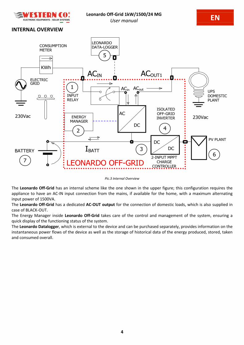
The Leonardo Off-Grid has an internal scheme like the one shown in the upper figure; this configuration requires the
appliance to have an AC-IN input connection from the mains, if available for the home, with a maximum alternating
input power of 1500VA.
The Leonardo Off-Grid has a dedicated AC-OUT output for the connection of domestic loads, which is also supplied in
case of BLACK-OUT.
The Energy Manager inside Leonardo Off-Grid takes care of the control and management of the system, ensuring a
quick display of the functioning status of the system.
The Leonardo Datalogger, which is external to the device and can be purchased separately, provides information on the
instantaneous power flows of the device as well as the storage of historical data of the energy produced, stored, taken
and consumed overall.
230Vac
ELECTRIC GRID
BATTERY IBATT
ACOUT1
4
LEONARDO
DATA-LOGGER
5
LEONARDO OFF-GRID
INPUT
RELAY
ISOLATED
OFF-GRID
INVERTER
AC
3
UPS
DOMESTIC
PLANT
1
230Vac
DC
CONSUMPTION
METER
ACin ACout
ENERGY
MANAGER
2
ACIN
6
DC
DC
2-INPUT MPPT
CHARGE
CONTROLLER
PV PLANT
7
KWh
Leonardo Off-Grid 1kW/1500/24 MG
User manual EN
5
CONNECTION DIAGRAM
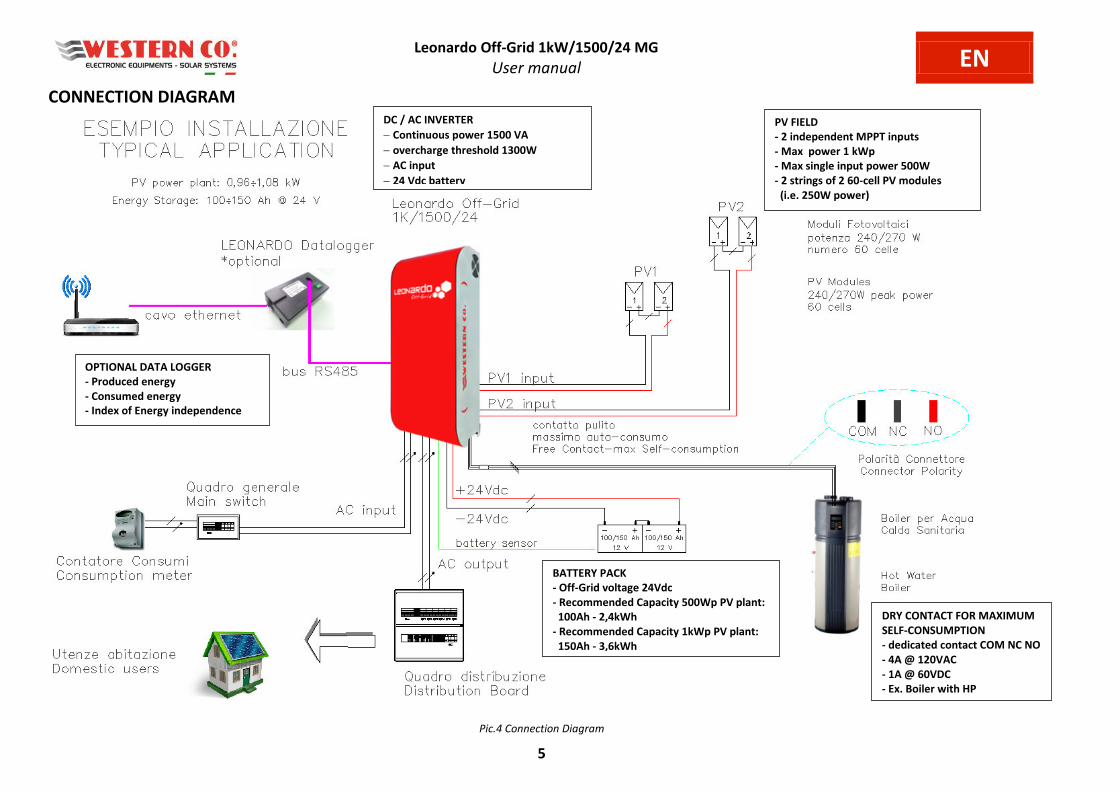
Pic.4 Connection Diagram
OPTIONAL DATA LOGGER
- Produced energy
- Consumed energy
- Index of Energy independence
BATTERY PACK
- Off-Grid voltage 24Vdc
- Recommended Capacity 500Wp PV plant:
100Ah - 2,4kWh
- Recommended Capacity 1kWp PV plant:
150Ah - 3,6kWh
DC / AC INVERTER
Continuous power 1500 VA
overcharge threshold 1300W
AC input
24 Vdc battery
DRY CONTACT FOR MAXIMUM
SELF-CONSUMPTION
- dedicated contact COM NC NO
- 4A @ 120VAC
- 1A @ 60VDC
- Ex. Boiler with HP
PV FIELD
- 2 independent MPPT inputs
- Max power 1 kWp
- Max single input power 500W
- 2 strings of 2 60-cell PV modules
(i.e. 250W power)
Leonardo Off-Grid 1kW/1500/24 MG
User manual EN
6
EXTERNAL PROTECTIONS
AC protections (not included)
Leonardo Off-Grid 1kW/1500/24 MG has an AC –OUT output line and an AC –IN input line. In addiction the device has a
NEUTRAL conductor of the grounding connection – TT system. The AC-OUT output line can be protected through a
differential magneto thermal breaker (AC type), with rated current In=16A and differential current Id=0,03A.
Also the AC-IN input line can be provided with a differential magneto thermal breaker (AC type), with rated current
In=16A and differential current Id=0,03A.
(Please note that in general this kind of breaker is already included in residence control panel.)
DC protections
After assembling and connecting the battery bank is possible to assembly the protection fuse of the battery on the
positive pole. Through the connection of the negative pole, the inverter will be activated.
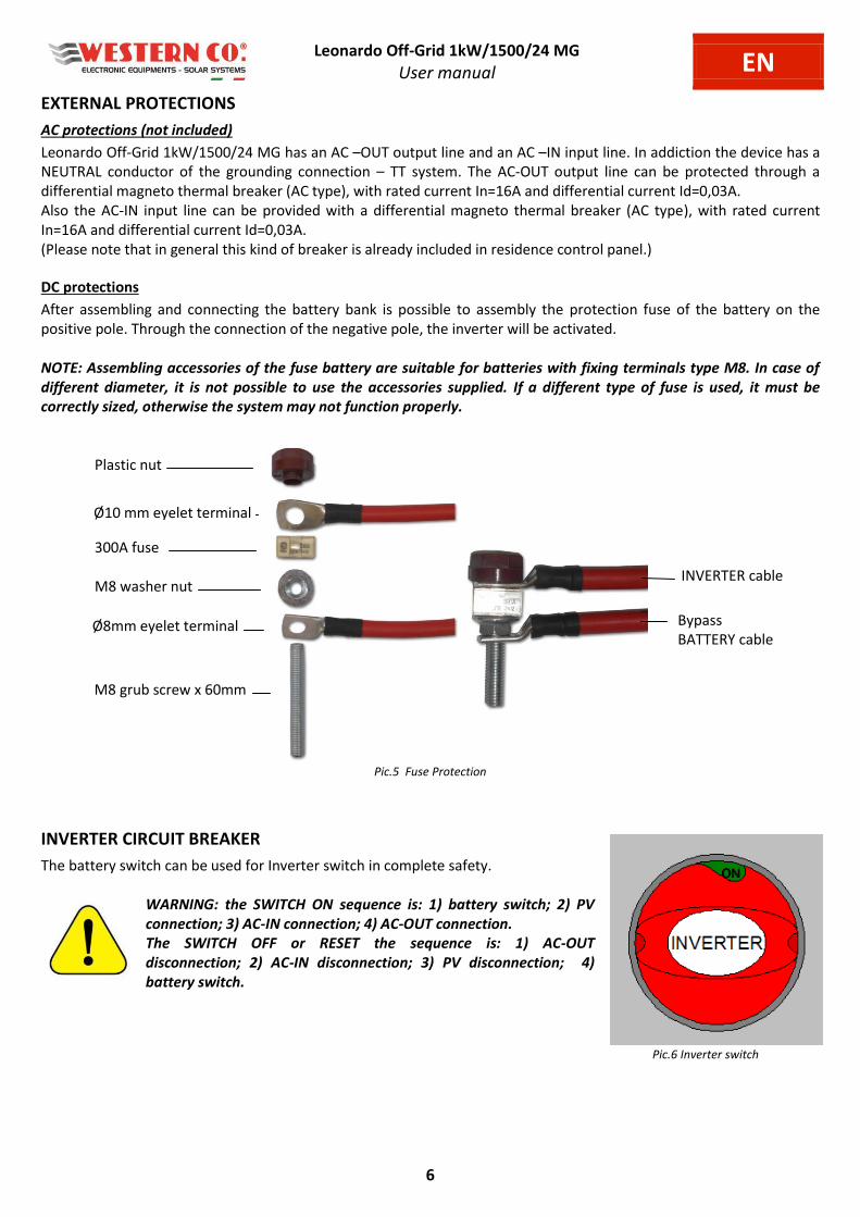
NOTE: Assembling accessories of the fuse battery are suitable for batteries with fixing terminals type M8. In case of
different diameter, it is not possible to use the accessories supplied. If a different type of fuse is used, it must be
correctly sized, otherwise the system may not function properly.
Pic.5 Fuse Protection
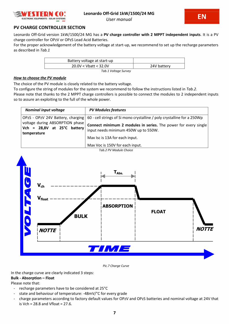
INVERTER CIRCUIT BREAKER
The battery switch can be used for Inverter switch in complete safety.
WARNING: the SWITCH ON sequence is: 1) battery switch; 2) PV
connection; 3) AC-IN connection; 4) AC-OUT connection.
The SWITCH OFF or RESET the sequence is: 1) AC-OUT
disconnection; 2) AC-IN disconnection; 3) PV disconnection; 4)
battery switch.
Pic.6 Inverter switch
Plastic nut
Ø10 mm eyelet terminal
300A fuse
M8 washer nut
Ø8mm eyelet terminal
M8 grub screw x 60mm
INVERTER cable
Bypass
BATTERY cable
Leonardo Off-Grid 1kW/1500/24 MG
User manual EN
7
PV CHARGE CONTROLLER SECTION
Leonardo Off-Grid version 1kW/1500/24 MG has a PV charge controller with 2 MPPT independent inputs. It is a PV
charge controller for OPzV or OPzS Lead Acid Batteries.
For the proper acknowledgement of the battery voltage at start-up, we recommend to set up the recharge parameters
as described in Tab.1
Battery voltage at start-up
20.0V < Vbatt < 32.0V 24V battery Tab.1 Voltage Survey
How to choose the PV module
The choice of the PV module is closely related to the battery voltage.
To configure the string of modules for the system we recommend to follow the instructions listed in Tab.2.
Please note that thanks to the 2 MPPT charge controllers is possible to connect the modules to 2 independent inputs
so to assure an exploiting to the full of the whole power.
Nominal input voltage PV Modules features
OPzS - OPzV 24V Battery, charging
voltage during ABSORPTION phase
Vch = 28,8V at 25°C battery
temperature
60 - cell strings of Si mono crystalline / poly crystalline for a 250Wp
Connect minimum 2 modules in series. The power for every single
input needs minimum 450W up to 550W.
Max Isc is 13A for each input.
Max Voc is 150V for each input. Tab.2 PV Module Choice
NOTTE
BULK
ABSORPTION
FLOAT
NOTTE
Vfloat
Vch
TAbs.
Pic.7 Charge Curve
In the charge curve are clearly indicated 3 steps:
Bulk - Absorption – Float
Please note that:
- recharge parameters have to be considered at 25°C
- state and behaviour of temperature: -48mV/°C for every grade
- charge parameters according to factory default values for OPzV and OPzS batteries and nominal voltage at 24V that
is Vch = 28.8 and Vfloat = 27.6.
Leonardo Off-Grid 1kW/1500/24 MG
User manual EN
8
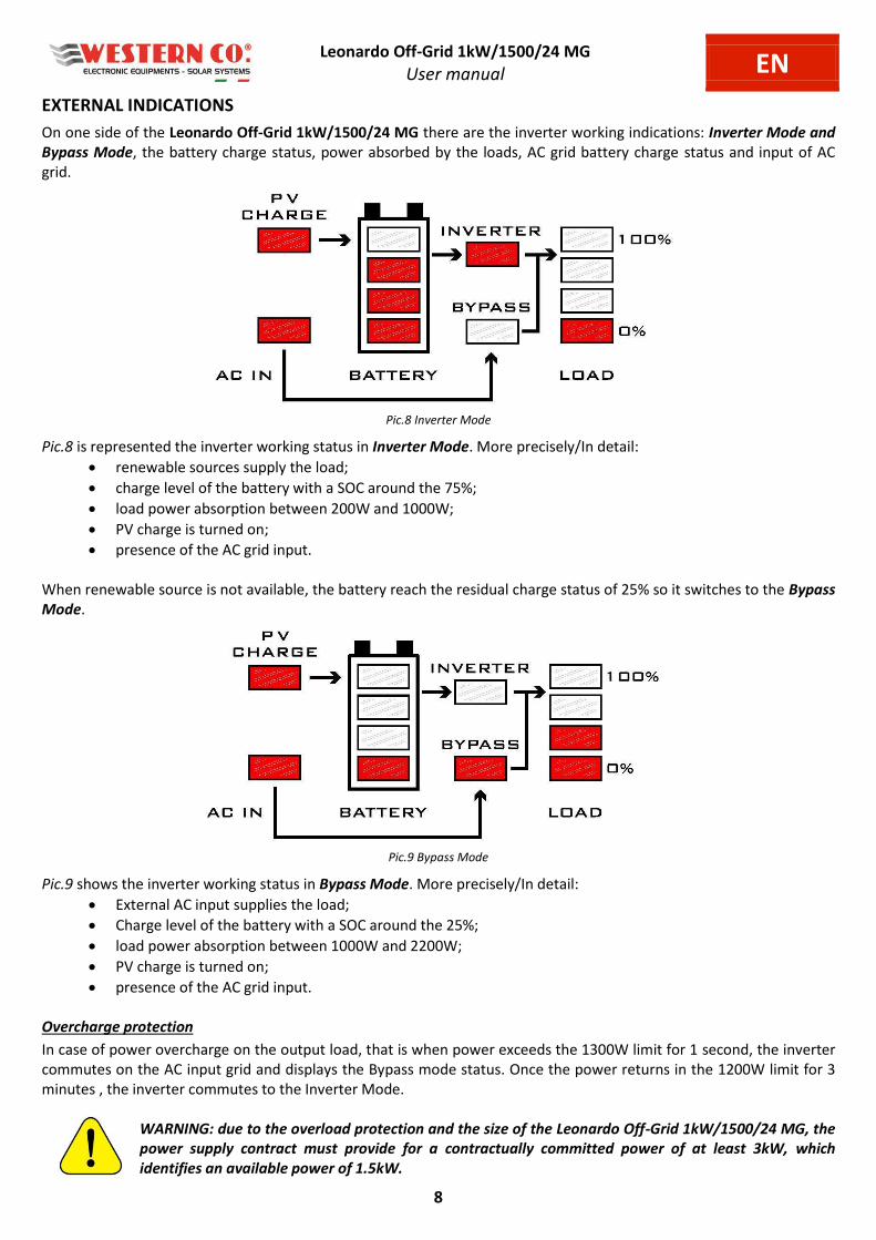
EXTERNAL INDICATIONS
On one side of the Leonardo Off-Grid 1kW/1500/24 MG there are the inverter working indications: Inverter Mode and
Bypass Mode, the battery charge status, power absorbed by the loads, AC grid battery charge status and input of AC
grid.
Pic.8 Inverter Mode
Pic.8 is represented the inverter working status in Inverter Mode. More precisely/In detail:
renewable sources supply the load;
charge level of the battery with a SOC around the 75%;
load power absorption between 200W and 1000W;
PV charge is turned on;
presence of the AC grid input.
When renewable source is not available, the battery reach the residual charge status of 25% so it switches to the Bypass
Mode.
Pic.9 Bypass Mode
Pic.9 shows the inverter working status in Bypass Mode. More precisely/In detail:
External AC input supplies the load;
Charge level of the battery with a SOC around the 25%;
load power absorption between 1000W and 2200W;
PV charge is turned on;
presence of the AC grid input.
Overcharge protection
In case of power overcharge on the output load, that is when power exceeds the 1300W limit for 1 second, the inverter
commutes on the AC input grid and displays the Bypass mode status. Once the power returns in the 1200W limit for 3
minutes , the inverter commutes to the Inverter Mode.
WARNING: due to the overload protection and the size of the Leonardo Off-Grid 1kW/1500/24 MG, the
power supply contract must provide for a contractually committed power of at least 3kW, which
identifies an available power of 1.5kW.

Leonardo Off-Grid 1kW/1500/24 MG
User manual EN
9
CONTROL LOGIC
Pic.10 Control Logic
Charge and output power Table
Charge SOC level 4, battery energy stored
is in a range between 75% - 100% of its
nominal capacity. (Voltage > 27,2 V)
Output power LOAD level 4, load power
absorption is greater than 4000W.
Charge SOC level 3, battery energy stored
is in a range between 60% - 75% of its
nominal capacity. (Voltage > 24 V)
Output power LOAD level 3, load power
absorption is is in a range between
2200W - 4000W.
Charge SOC level 2, battery energy stored
is in a range between 40% - 60% of its
nominal capacity. (Voltage > 23 V)
Output power LOAD level 2, load power
absorption is is in a range between
1000W - 2200W.
Charge SOC level 1, battery energy stored
is in a range between 30% - 40% of its
nominal capacity. (Voltage > 21 V)
Output power LOAD level 1, load power
absorption is is in a range between
200W - 1000W.
Tab.3 State of Charge and Output Power
Home Consumption Inverter Limitation PV Production Grid Power Battery Power
Leonardo Off-Grid 1kW/1500/24 MG
User manual EN
10
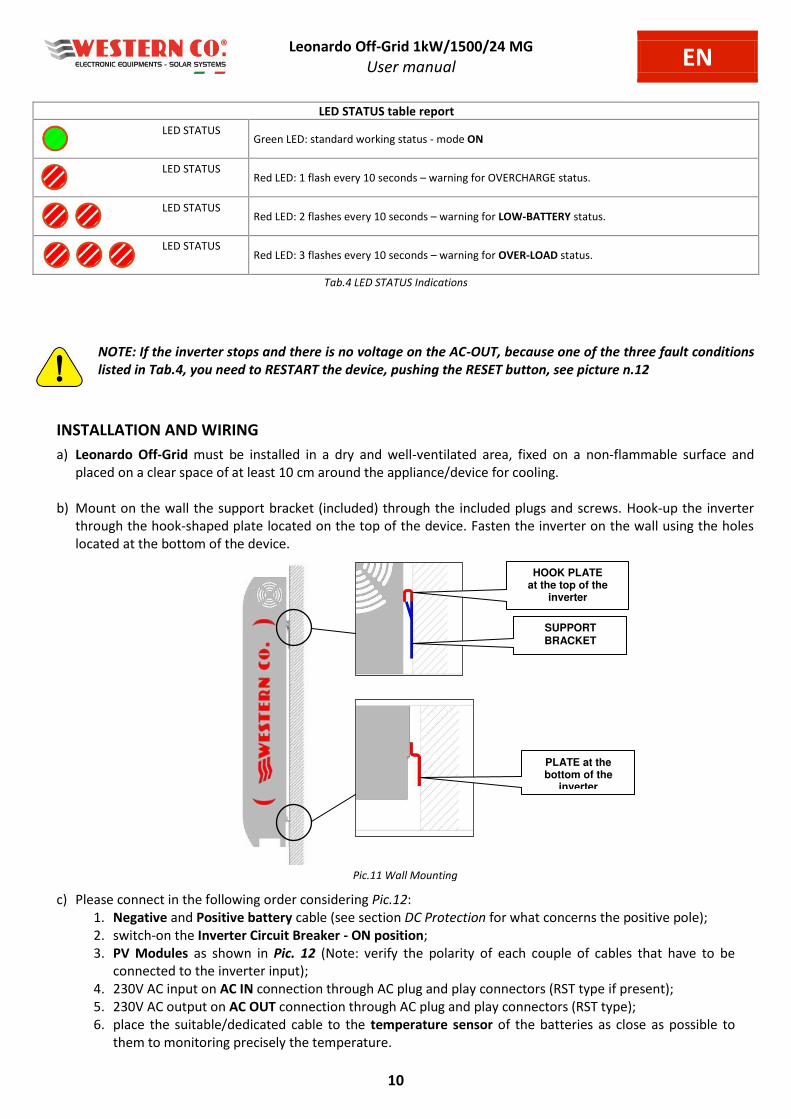
LED STATUS table report
LED STATUS Green LED: standard working status - mode ON
LED STATUS Red LED: 1 flash every 10 seconds – warning for OVERCHARGE status.
LED STATUS Red LED: 2 flashes every 10 seconds – warning for LOW-BATTERY status.
LED STATUS Red LED: 3 flashes every 10 seconds – warning for OVER-LOAD status.
Tab.4 LED STATUS Indications
NOTE: If the inverter stops and there is no voltage on the AC-OUT, because one of the three fault conditions
listed in Tab.4, you need to RESTART the device, pushing the RESET button, see picture n.12
INSTALLATION AND WIRING
a) Leonardo Off-Grid must be installed in a dry and well-ventilated area, fixed on a non-flammable surface and
placed on a clear space of at least 10 cm around the appliance/device for cooling.
b) Mount on the wall the support bracket (included) through the included plugs and screws. Hook-up the inverter
through the hook-shaped plate located on the top of the device. Fasten the inverter on the wall using the holes
located at the bottom of the device.
Pic.11 Wall Mounting
c) Please connect in the following order considering Pic.12:
1. Negative and Positive battery cable (see section DC Protection for what concerns the positive pole);
2. switch-on the Inverter Circuit Breaker - ON position;
3. PV Modules as shown in Pic. 12 (Note: verify the polarity of each couple of cables that have to be
connected to the inverter input);
4. 230V AC input on AC IN connection through AC plug and play connectors (RST type if present);
5. 230V AC output on AC OUT connection through AC plug and play connectors (RST type);
6. place the suitable/dedicated cable to the temperature sensor of the batteries as close as possible to
them to monitoring precisely the temperature.
HOOK PLATE at the top of the
inverter
SUPPORT
BRACKET
PLATE at the bottom of the
inverter dell’inverter

Leonardo Off-Grid 1kW/1500/24 MG
User manual EN
11
Together with the device, is provided a cable to connect the batteries of a total length 1.5m and cable cross section
25mmq. Suggestion: install the battery pack at a total distance so to maintain the original length of the cable.
In case the battery pack is composed of further elements in series or in parallel using a cable with a minimum cable
cross section of 25mmq.
Since the device is equipped with a 1.5 m long and 25 mmq section battery connection cable, it is absolutely
recommended to install the battery bank at a distance such as to keep the original connection cable. To increase the
distance with the battery bank causes an electrical drop on the cable during operation and therefore an incorrect
reading of the battery voltage.
Use the cable supplied to connect to the main battery terminals and in the case of a battery bank made up of several
elements in series or in parallel, use a cable with a minimum section of 25mmq for wiring each element in series or in
parallel.
It is recommended to install the unit on a solid wall in a vertical position in order to ensure adequate air circulation due
to forced ventilation of the unit. For this reason, installation in dusty and dirty areas must also be avoided.
Pic.12 Wiring Cable
DC input Battery Cable Length 1.5 m Section 25 mm^2
Temperature Sensor Input
Cable Length 1.5 m
DRY CONTACT MAX SELF-CONSUMPTION
No. 3 pins of the contact COM-BLACK NC-WHITE NO-RED
WHITE PLUG SYNC
PV INPUT + No. 2 positive inputs Plug and play wiring
4-6mm^2 (In Pic. Male counterparts)
AC OUTPUT Cablaggio tramite connettori plug
and play a 3 poli - 6mm^2
PV INPUT - No. 2 negative inputs Plug and play wiring
4-6mm^2 (in Pic. Female counterpart)
AC INPUT Wiring through plug and play
connectors 3-pin - 6 mm^2
RESET BUTTON
DATA-LOGGER BLACK PLUG

Leonardo Off-Grid 1kW/1500/24 MG-SL
User manual EN
12
STARTING AND TESTING THE OFF-GRID
As soon as effectuate the connections as shown in Pic.12, start and test the system following these steps:
1) Verify the starting of the Leonardo Off-Grid 1kW/1500/24 at the end of the wiring of the cables to the
battery terminals;
2) Verify the correctness of the recharge of the battery, if not verify the installation of the battery pack;
3) Activate the AC input line, if any, through the AC-IN connection;
4) Verify the starting of the AC-OUT output, if there is a load, the inverter provides power and the status is
a aila le i the lighti g i di atio s LOAD ;
5) According to the recharge condition of the battery, the presence of the grid input is evident the correct
functioning of the Inverter Control Logic (see Pic. 10).
POSSIBLE PROBLEMS AND SOLUTIONS
AC IN led off Check the input voltage and the wiring of the AC-IN connector.
Absence of AC-OUT output voltage Check the wiring of the AC-OUT connector. Check if the Energy Manager
has both BYPASS and INVERTER LEDs off.
Both "bypass" and "inverter" LEDs off: Reset the inverter by pressing the RESET button. With the inverter
off, turn only the DC Battery disconnect switch on and check that the BATTERY LED and INVERTER LED are
switched on. Check the integrity of any DC protection fuses. If the problem persists, we recommend that you
contact Western CO technical support.
PV CHARGE LED always off: Check the wiring of the PV strings.
STATUS LED off: Reset the inverter according to the manual.
APPLICAZIONI TRIFASE O PARALLELO CON VERSIONE SLAVE SL
The Leonardo Off-Grid 1kW/1500/24 MG, Master version for applications with mains input can be installed in THREE -
PHASE or PARALLEL type systems using the code Leonardo Off-Grid 1kW/1500/24 SL, SLAVE version.
Every installation includes no. 1 Master inverter and N Slave inverter depending on the configuration.
For example:
Three-phase system tot. 4,5Kw
Phase L1 no.1 Master - Phase L2 no.1 Slave - Phase L3 no.1 Slave
Pic.13 Wiring Diagram Sync Control BUS for 4,5kW Three-phase System
INVERTER MASTER L1
A - Plug Datalogger
B - Plug synchronism
INVERTER SLAVE L2
A - Plug synchronism
B - Plug synchronism
INVERTER SLAVE L3
A - Plug synchronism
B - non connesso
SYNC CABLE
Patch Cable 8 pins
DATALOGGER
CABLE
Patch Cable
8 pins
SYNC CABLE
Patch Cable 8 pins
Leonardo Off-Grid 1kW/1500/24 SL
User manual IT
13
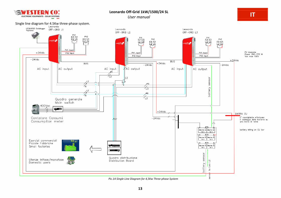
Single line diagram for 4.5Kw three-phase system.
Pic.14 Single Line Diagram for 4,5Kw Three-phase System
Leonardo Off-Grid 1kW/1500/24 SL
User manual EN
14
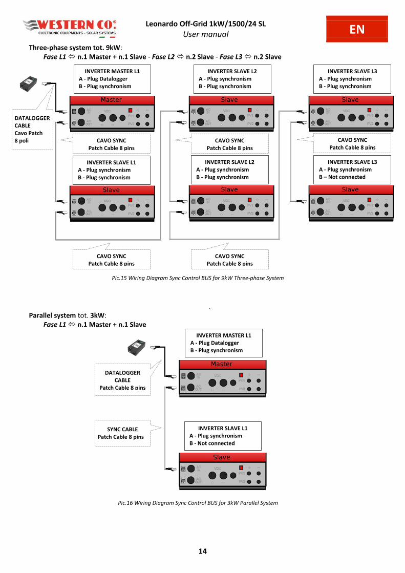
Three-phase system tot. 9kW:
Fase L1 n.1 Master + n.1 Slave - Fase L2 n.2 Slave - Fase L3 n.2 Slave
Pic.15 Wiring Diagram Sync Control BUS for 9kW Three-phase System
.
Parallel system tot. 3kW:
Fase L1 n.1 Master + n.1 Slave
Pic.16 Wiring Diagram Sync Control BUS for 3kW Parallel System
INVERTER MASTER L1
A - Plug Datalogger
B - Plug synchronism
INVERTER SLAVE L2
A - Plug synchronism
B - Plug synchronism
INVERTER SLAVE L3
A - Plug synchronism
B - Plug synchronism
INVERTER SLAVE L1
A - Plug synchronism
B - Plug synchronism
INVERTER SLAVE L2
A - Plug synchronism
B - Plug synchronism
INVERTER SLAVE L3
A - Plug synchronism
B – Not connected
CAVO SYNC
Patch Cable 8 pins
DATALOGGER
CABLE
Cavo Patch
8 poli
CAVO SYNC
Patch Cable 8 pins
CAVO SYNC
Patch Cable 8 pins
CAVO SYNC
Patch Cable 8 pins
CAVO SYNC
Patch Cable 8 pins
DATALOGGER
CABLE
Patch Cable 8 pins
SYNC CABLE
Patch Cable 8 pins
INVERTER SLAVE L1
A - Plug synchronism
B - Not connected
INVERTER MASTER L1
A - Plug Datalogger
B - Plug synchronism

Leonardo Off-Grid 1kW/1500/24
User manual EN
15
ELECTRICAL FEATURES Leonardo Off-Grid
1kW / 1500 / 24 MG
Leonardo Off-Grid
4kW / 3000 / 48 MG
Leonardo Off-Grid
4kW / 5000 / 48 MG
Leonardo Off-Grid
8kW / 8000 / 48 MG
INV
ER
TE
R
Min Typ Max Min Typ Max Min Typ Max Min Typ Max
Output power Pout - 1500VA 3.000W - 3.000VA 6.000W - 5.000VA 10.000W - 8.000VA 16.000W
Battery voltage Vbatt 20,0V 24V 33V 40,0V 48V 66V 40,0V 48V 66V 40,0V 48V 66V
Output voltage Vac - 230V - - 230V - - 230V - - 230V -
Output frequency Fac - 50Hz
±0,1% - -
50Hz
±0,1% - -
50Hz
±0,1% - -
50Hz
±0,1% -
Inverter switching time
<> Bypass mode Tsw - 10mS - - 10mS - - 10mS - - 10mS -
Overcharge threshold Poc - 85% - - 85% - - 85% - - 85% -
Efficiency Eff - 94% - - 95% - - 95% - - 95% -
Absorption during
Bypass Mode Pbp - <4W - - <5W - - <6W - - <6W -
Absorption with inverter
standby Psb - 10W - - 16W - - 25W - - 25W -
Switching voltage
Inverter-Mode / Bypass-
Mode
Tba 22,9V 23,0V 23,1V 45,9V 46,0V 46,1V 45,9V 46,0V 46,1V 45,9V 46,0V 46,1V
End-low battery voltage Tbs 27,1V 27,2V 27,3V 54,3V 54,4V 54,5V 54,3V 54,4V 54,5V 54,3V 54,4V 54,5V
Warning for internal
over-temperature Tot 65°C 65°C 65°C 65°C
Working temperature Tamb -10°C 25°C 60°C -10°C 40°C 60°C -10°C 25°C 60°C -10°C 25°C 60°C
PV
CH
AR
GE
R
Min Typ Max Min Typ Max Min Typ Max Min Typ Max
Battery voltage Vbatt - 24,0V - - 48,0V - - 48,0V - - 48,0V -
MPPT inputs Nmpp - 2 - - 4 - - 4 - - 4 -
MPPT input current Ipan - - 13,0A - - 13,0A - - 13,0A - - 26,0A
Open circuit PV module
voltage Vpan - - 150 V - - 150V - - 150V - - 150V
Max. input power Pch - 500W - - 1kW - - 1kW - - 2 kW -
Max. total power Pmax - - 1 kW - - 4 kW - - 4 kW - - 8 kW
Charge voltage at 25°C VEoC - 28,8V - - 57,6V - - 57,6V - - 57,6V -
ABSORPTION time Tabs - 4h - - 4h - - 4h - - 4h -
FLOAT voltage Vflt - 27,6V - - 55,2V - - 55,2V - - 55,2V -
Efficiency Eff - 97,2% - - 97,2% - - 97,2% - - 97,2% -
Balance of the VEoC
function of the battery
temperature (Tbatt)
Vtadj - -96
mV/°C - -
-96
mV/°C - -
-96m
V/°C - -
-96
mV/°C -
Self-consumption Iq - 12 mA - - 12 mA - - 12 mA - - 12 mA -
Working temperature Tamb -10°C 25°C 60°C -10°C 25°C 60°C -10°C 25°C 60°C -10°C 25°C 60°C
Dissipated power Pdiss 66W 66W 66W 66W
EN
CLO
SU
RE
Min Typ Max Min Typ Max Min Typ Max Min Typ Max
Cable cross section of
the battery -
25mm
2 -
-
25mm
2 -
-
35mm
2 -
-
50mm
2 -
Cable length of the
battery - 1,5mt - - 1,5mt - - 1,5mt - - 1,5mt -
Protection grade IP20 IP20 IP20 IP20
Size 315x750x130 mm 395x940x250 mm 395x940x250 mm 395x940x300 mm
Weight 14 Kg 25 Kg 37 Kg 55 Kg
Tab.5 Electrical Features

Leonardo Off-Grid 1kW/1500/24
User manual EN
16
MECHANICAL FEATURES AND WEIGHT Leonardo Off-Grid 1kW/1500/24 MG = 14 kg
Pic.17 Mechanical Features
WARRANTY
Western CO. Srl guarantees the good quality and good design of its own Products obliging itself, during the warranty
period of 5 (five) years, to repair or replace at its sole discretion, for free, those defective parts owing to poor quality
of material or defect in workmanship.
The defective product must be returned to Western CO. Srl or to the company delegated by Western CO. to make
produ t support, at usto er’s e pe ses, together ith a op of the i oi e oth for repairi g a d arra t replacement. The costs of re-installation of the equipment will be borne by the customer.
Western CO. Srl will bear the transport expenses of the repaired or replaced product.
The warranty does not cover Products that, according to our discretion, are defective due to natural wear, showing
damages caused by incompetence or negligence of the customer, imperfect installation, by tampering or other
interventions different by the instructions supplied by us. The warranty is not valid also in case of damages coming
from:
- transport and/or incorrect storage of the product.
- force majeure or catastrophic events (frost to temperatures below -20 ° C, fire, flood, lightning, vandalism, and so
on).
All of the abovementioned guarantees are the sole and exclusive agreement which supersedes any proposal or
agreement, oral or written, and any other communication made between the manufacturer and the purchaser in
respect of the above.
For any dispute the jurisdiction is Ascoli Piceno.
WASTE DISPOSAL
Western CO. as manufacturer of the electrical device herein described and in accordance
with DL 07/25/2005 n 151, informs the consumer that this product, once abandoned, must
be delivered to an authorized collection center or, in case of purchase of an equivalent
equipment, it can be returned free of charge to the distributor of the new equipment. The
penalties will be applied by individual Municipalities.
WESTERN CO. Srl
Via Pasubio, 1
63074 San Benedetto del Tronto (AP)
tel: (+39) 0735 751248 fax: (+39) 0735 751254
e-mail: [email protected]
web: www.western.it

Questo documento è di proprietà di WESTERN CO. Srl - Tutti i diritti sono riservati - La
riproduzione e l'uso delle informazioni contenute nel presente documento sono vietati senza il
consenso scritto di WESTERN CO. Srl.
This document is the property of WESTERN CO. Srl - All rights are reserved - Reproduction and
use of information contained within this document is forbidden without the written consent of
WESTERN CO. Srl.
Copyright © 2018 - Western CO. Srl