LEHKÁ STAVBA V KOLEJOVÝCH VOZIDLECH
40
This presentation is part of project CZ.1.07/2.2.00/15.0383 Innovations of Study specialisation Transport Vehicles and Handling Machinery with respect to market needs Ing. Vladislav Kemka 2011, UWB in Pilsen KKS/ZDMT Vessels – theory, design Presentation 3
Transcript of LEHKÁ STAVBA V KOLEJOVÝCH VOZIDLECH

This presentation is part of project CZ.1.07/2.2.00/15.0383 Innovations of Study specialisation Transport Vehicles and Handling Machinery
with respect to market needs
Ing. Vladislav Kemka
2011, UWB in Pilsen
KKS/ZDMT Vessels – theory, design
Presentation 3

Vessels
ZDMT Ing. Vladislav Kemka ZČU v Plzni
2
Buoyancy: Buoyancy is the ability of a body to float on the surface and is an effect of its own hydrostatic lift. As a body surfaces, the volume of the submerged part decreases and hydrostatic lift also reduces. When the size of the buoyancy force decreases to the value of gravitational force, these two forces are in equilibrium. The surfacing of the body then stops at a position corresponding to the equilibrium of the forces. The ability of a body to fulfill this task is called buoyancy. To achieve buoyancy the basic conditions of buoyancy must be met.
1) Absolute density of body must be less than density of liquid. 2) Total weight of body G must equal the buoyancy force Fz. 3) The center of gravity and buoyancy forces must lie in the longitudinal axis of the body.

Vessels
ZDMT Ing. Vladislav Kemka ZČU v Plzni
3
Hydrostatic lift: A body immersed in fluid is supported by a force equal to the weight of fluid displaced. By applying Archimedes’ law, we arrive at the results of the Bernoulli equation which states that hydraulic pressure changes linearly with depth. A body submerged in fluid creates a force on surface element dS of dF=p.dS=γ.z.dS perpendicular to the surface element. Fz = γ.V = ρ.g.V Surface element : dS
Volume element : Force: Buoyancy force: Submerged volume of body: Total buoyancy force: Fz = γ.V = ρ.g.V
αcos⋅⋅= dSzdVdSzdF ⋅⋅= γ
dVdSzdFz ⋅=⋅⋅⋅= γαγ cos
αcos⋅⋅== ∫∫ dSzdVV
αγ cos⋅⋅⋅= ∫ dSzFz

Vessels
ZDMT Ing. Vladislav Kemka ZČU v Plzni
4
The balance of forces in the vertical direction :
For positive displacement vessels, i.e. vessels of all shapes and sizes, common to all major cargo and passenger ships, all boats powered by oars and paddles, for nearly all sailing boats, all boats with low-power engines, for all tourist cruise boats, all houseboats, etc., is based on the validity of Archimedes’ law. For the balance of forces in the vertical direction, the displacement (buoyancy, lift) is equal to the weight (mass) of the vessel. This can be expressed as: D = G or ρgV = mg Where D [kN] – displacement or lift D= γ V = ρgV G [kN] – mass of ship V [m3] – volume displacement can be determined ρV [kg] – mass displacement, or the volume of displaced material, can be written thus: These are some basic concepts important in the design and construction of a ship.
gDDV⋅
==ργ
gDmV ==⋅ρ

Vessels
ZDMT Ing. Vladislav Kemka ZČU v Plzni
5
Movement of ships on the surface:
Ships move on the surface with 6° of freedom, 3 sliding moves in the direction of the principal coordinate axis, and 3 rotational moves around the principal coordinate axis. Movement can be forward-backward, lateral, emerging-submerging, or rotational, known as roll, pitch, and yaw. Roll is a rotational movement in the transverse plane around the longitudinal axis of the vessel. The unit of displacement is inclination, or the angle of inclination in degrees. Pitch (rocking from bow to stern) is rotational movement in the longitudinal plane around the lateral axis of the ship. Movement around the vertical axis is yaw.
Ships
ZDMT Ing. Vladislav Kemka ZČU v Plzni
6
Ship stability:
Ship stability is the ability of a ship to return unaided to its original horizontal position when an external force ceases to act on it. Absolute stability is found in ships which are so stable that they can right themselves unaided even when completely capsized (e.g. sailing ships with heavy keels and watertight hulls. Depending on the type of external loading, stability is divided into static and dynamic stability. Depending on the direction of tilt, stability is either lateral or longitudinal. When the tilt from the horizontal position is small, it is called initial stability (up to 10 degrees), or stability at greater angles of tilt. Static stability is broken due to external resting forces or by them gradually increasing up to a limit. Dynamic stability is caused by impacts and variable forces (gusting winds or waves, breakage of a tug head line at full power, etc.)

Ships
ZDMT Ing. Vladislav Kemka ZČU v Plzni
7
Lateral stability: Lateral stability at small inclinations up to 8° to 15°. G is the centre of gravity of the ship and it does not change during inclination. The force (weight) of the whole ship acts on this point G= V.γ = V.ρ.g. The centre of buoyancy of the submerged part is point D0 and displacement force acts on it. If the ship is inclined from the horizontal position a/ to position b/ the angle of heel is φ1, point D0 inclines from its original position to D1, which is the centre of buoyancy of the submerged part of the hull MWL1.

Ships
ZDMT Ing. Vladislav Kemka ZČU v Plzni
8
A ship is stable when buoyancy D and the weight of the ship G exert an inclining moment and return the ship to its original horizontal position. The value of lateral stability (or the effect of the moment of stability) is expressed by arm h (the arm of stability: the larger it is, the more stable it is) and also the height of the intersection of the carrier of buoyancy force D with the vertical axis of the ship above the centre of gravity G (M1). As stated above, this is an imaginary centre point of the inclined ship called the metacentric point M1 (metacentre: the higher it is, the more stable it is). In practice, metacentric height is used for static stability, which is the distance of the metacentre from the centre of gravity of the ship. i.e. the ship is stable when M1 lies above the centre of gravity of the ship G (i.e. k>0).
G1M k =

Ships
ZDMT Ing. Vladislav Kemka ZČU v Plzni
9
Lateral stability :
The size of stabilizing moment From the cross section we derive Attwood’s formula for the metacentric position, the metacentric radius ; the units are [m] = [m4] / [m3]. Ix is area moment of inertia at the water plane at the longitudinal axis of symmetry x, V is the volume of the submerged part of the hull.
ϕsin⋅⋅=
⋅=
kDMhDM
gstabilizin
gstabilizin
Gv zzrkGKKDMDMG
−+=−+=
0
00
VI
r x=0

Ships
ZDMT Ing. Vladislav Kemka ZČU v Plzni
10
Lateral stability: It is generally true that safe stability requires a large metacentric height. However, a ship with a high metacentre has hard stability (it vigorously reacts to maneuvering, has hard jerking movements which are unfavourable). Soft stability is found in sea ships with a metacentric height of k = 0.6 to 0.8 m. An indicator of hard or soft stability is the duration of inclination of the ship. If the inclination of a ship from one side to the other is less than 10seconds, this is a very fast inclination and it has hard stability. These kinds of movements place great stress on the large and heavy driving machinery onboard.

Ships
ZDMT Ing. Vladislav Kemka ZČU v Plzni
11
Basic equilibrium position of a ship: MWL – main water level(draught); G – ship’s centre of gravity, where forces of gravity act on the ship; D0 ,D1 ,D2 – locations (centres) of forces of displacement D, with tilt, the centre of buoyancy is the shaded area D1 for φ1 (D2 for φ2); K – a point at the base of the ship which is used to measure the height of the ship’s centre of gravity and location of buoyancy; zG – height of position of ship’s centre of gravity in relation to point K and where the force of activity acts on the ship, zV - height of position of ship´s centre of buoyancy; r0 - metacentric radius.

Ships
ZDMT Ing. Vladislav Kemka ZČU v Plzni
12
Inclination of ships at small angles (to 10°): Centre of gravity G remains in the original position. Point D0 moves to the right to D1 and again displacement force D acts on it, the volume of displaced fluid marked by the shaded area. Point H is the vertical section of point G; their distance forms the frame of couple forces which is the returning-stabilizing- moment, which tries to return the ship to its original position. Metacentre M is the intersection of the original carrier of displacement force with the new carrier of displacement force, forming inclination φ1 . Distance k = MG is the metacentric height of the ship; k > 0 is the measure of the ship’s stability (k ≤ 0 unstable).

Ships
ZDMT Ing. Vladislav Kemka ZČU v Plzni
13
Inclination of ships at greater angles (above 15°):
here the centre of buoyancy changes a lot and the original M = M1 changes so that M1 ≠ M2

Ships
ZDMT Ing. Vladislav Kemka ZČU v Plzni
14
Sailing resistances: Sailing resistance is a summary of all forces acting against the movement of the ship and is dependent on the following factors: - speed of movement - size of hull - shape of hull - sea/waterway Total sailing resistance is calculated using the following equation formed from the totals of individual resistances.

Ships
ZDMT Ing. Vladislav Kemka ZČU v Plzni
15
Ship resistance:
Symbol Name Definition
Dt Shape resistance Resistance caused by the shape of the hull.
Dτ Surface (frictional) resistance
Resistance caused by friction of water on hull in relation to its size, construction, speed and water temperature.
Dk Wave resistance Resistance created by waves on the surface as they flow around the ship.
Dv
Vortex resistance A kind of shape resistance caused by the wake (wake vortex region is behind the ship, where there is flow separation).
Dd
Added resistance Air resistance Its effects are directly dependent on:
- Size of exposed parts of ship(including superstructure) - Cruising speed - Speed and direction of wind
Influence of angle of water surface
The inclination of the surface of an open river is almost identical to the inclination of the river bed. It is given in percent.
Influence of bridge columns
Mostly with old stone bridges with massive columns. Results in narrowing flow profile, raising the water surface and increasing speed of flow.
Influence of uneven bed
Causes increased resistance and loss of cruising speed (on Czech rivers from 3 to 5%). The shallower the river, the greater the influence of an uneven bed.
Resistance of a pushing configuration
A pushing configuration is a rigid or articulated connection of ships for push towage . The resistance of pushing configurations is 10 to 15% less than for towing .

Ships
ZDMT Ing. Vladislav Kemka ZČU v Plzni
16
The influence of waterway profile on ships: The depth and width of a waterway can influence the passage of a ship. Sailing along a waterway where the space below or alongside the ship is very narrow leads to increased speed. This results in increased surface tension. As speed increases, and the depth (or width) decreases, the wave in front of the ship gets bigger, influenced by the imperfect demulsification of the water. The ship then inclines along its lateral axis towards the rear. At critical speeds wave resistance reaches its maximum tolerable value. The greater this resistance, the smaller is the value of the ratio between the cross section of the waterway and the area of the largest cross section of the submerged part of the hull.

Ships
ZDMT Ing. Vladislav Kemka ZČU v Plzni
17
Main dimensions of a ship:
Greatest length LMAX
Greatest width BMAX Greatest height HMAX Length at main water line LHVR (LMWL)
Designed width B Width at frame Bž Side height H Draught T Keel draught TMAX Freeboard F Buoyancy D Weight of ship(full) G

Ships
ZDMT Ing. Vladislav Kemka ZČU v Plzni
18
Drawing of a hull:
A design drawing shows the surface of a hull and superstructure. The surface of the hull is shown by curved lines (on a map they are
contour lines) The lines are thus a series of horizontal planes which cut through the
hull. The different planes are: • Planes parallel to the basic horizontal plane of the ship
– Water line – The most important is the ‘main water line’ (MWL) which lies at
the normal (designed) draught of the ship • Planes parallel to the axial plane of the ship
– Flank lines • Planes perpendicular to the basic and axial plane of the ship
– Frame lines – The most important frame line is at the halfway point of the ship
– the main frame/strut • Planes inclined to the axial plane of the boat below a suitable angle -
- Intersecting lines

Ships
ZDMT Ing. Vladislav Kemka ZČU v Plzni
19
Lines of a ship:

Ships
ZDMT Ing. Vladislav Kemka ZČU v Plzni
20
Movement of ships on the water surface:
The movement of a motorboat on the water surface is possible by the following means:
• displacement
• planing
• hydrofoil
These 3 basic modes are fundamentally different and the submerged part of the hull also differs. There are also transitional regimes between the modes-partial planing and partial hydrofoiling.

Ships
ZDMT Ing. Vladislav Kemka ZČU v Plzni
21
Displacement running: • During displacement running, a ship displaces water to the side and below it. The bow divides water, it flows around the entire length of the hull and connects and closes behind it once again. The ship does not change its depth or its longitudinal inclination. It is the most widespread and easy to achieve form of sailing.
• Speed of displacement running can only reach certain limits which depend on the length of the ship. It cannot be increased no matter what the power of the motor. The maximum speed of displacement running can be calculated from the formula [km/h], where L is the length of the ship at the main waterline in metres. • Speed is limited by the fact that at maximum speed the stern of the ship drops into the first wave trough made by the bows. It thus lies on a half wave with its bow raised. In this position the ship has high resistance because it is as if the ship is going constantly uphill. A ship cannot avoid this unless it has suitably shaped bows and weight distribution.
• Most suitable speed [km/h] Lv 4.3=
Lv 6=

Ships
ZDMT Ing. Vladislav Kemka ZČU v Plzni
22
Planing: • Planing is more demanding on the properties of a ship and can only be achieved by ships of a certain shape and with a certain power of motor. They must have a much higher power than displacement ships and so are less economical. It is however essential if we want to reach speeds higher than the limited speed of displacement ships. • Planing is dependent on the ship partially rising from the water surface; a certain force must act on the base of the ship- hydrodynamic lift. Its size depends on the shape of the base, its area and its speed. The most important factor is speed-the ship must have a high enough speed for planing. With a good shape of base and sufficient area, the lowest speed for initiation of planing can be calculated from the formula: [km/h] • For the speed limit for initiation of planing and the limit for displacement running, i.e. at speeds of v = there exists a transitional regime. However, even for this regime the ship must have a shape enabling planing, not a displacement shape. Good planing is achieved at speeds of [km/h]
Lv 8=
Lv 11=
L)86( −

Ships
ZDMT Ing. Vladislav Kemka ZČU v Plzni
23
Displacement and planing:
Displacement running planing

Ships
ZDMT Ing. Vladislav Kemka ZČU v Plzni
24
Calculating power and speed of a ship: • Power– using guide number/figure
– Planing sports boat • Cylinder volume ccm3 = LMWL in [cm]
– Displacement ship • Minimum power = 2 x LMWL x B • Normal power = 3 x LMWL x B
• Speed – from the diagram
– Dimensions, mass and shape of ship, location of centre of gravity, power of engine, etc.

Ships
ZDMT Ing. Vladislav Kemka ZČU v Plzni
25
Speed of a ship:
Fig. 9. Diagram II to determine speed of ship with V-profile hull. Capable of planing. V – ship speed (km/h), G – ship weight(kg), P – nominal power(k)
Diagram I to determine speed of displacement and semi-planing ships v – ship speed (km/h), G – ship weight (ton) P – nominal power of engine (HP),

Ships
ZDMT Ing. Vladislav Kemka ZČU v Plzni
26
Basic constructional elements of ships:

Ships
ZDMT Ing. Vladislav Kemka ZČU v Plzni
27
Ship:
A ship is formed of two basic construction elements, the hull and the superstructure.

Ships
ZDMT Ing. Vladislav Kemka ZČU v Plzni
28
Main parts of a ship:
Superstructure The superstructure is the part of the ship above the deck. It varies from ship to ship depending on its function. Hull The hull is the framework of the ship, including all other construction elements, deck and bulkheads, bounded by the plating and from above the main deck. The basic construction elements of a ship’s hull:
a) framework
b) plating
c) deck

Ships
ZDMT Ing. Vladislav Kemka ZČU v Plzni
29
Framework of a ship’s hull:
The hull framework is the primary set of constructional components of multiple types of struts whose terminology varies according to the orientation, function and location in the framework.
-Beam Lateral support for deck, cockpit, cabins, etc.
-Post (bow, stern) Main support for ends of hull frame. Connects directly to keel.
-Stringer Longitudinal support of hull
-Transverse frame Transverse support for side and base of hull.
-bulkhead Vertical dividing wall inside hull.

Ships
ZDMT Ing. Vladislav Kemka ZČU v Plzni
30
Ship equipment:
a) Ship power unit
- engine - Gear box - propulsion element
b) Ship equipment - anchor - rudder - drainage, - wind - other, e.g. towing, pulling, pushing, etc.
c) Accessories - anchor - tying - rescue - other, e.g. radio, navigational, meteorological, sonar, etc.

Ships
ZDMT Ing. Vladislav Kemka ZČU v Plzni
31
Ship engines:
Classification:
Ships
ZDMT Ing. Vladislav Kemka ZČU v Plzni
32
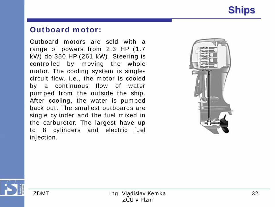
Outboard motor:
Outboard motors are sold with a range of powers from 2.3 HP (1.7 kW) do 350 HP (261 kW). Steering is controlled by moving the whole motor. The cooling system is single-circuit flow, i.e., the motor is cooled by a continuous flow of water pumped from the outside the ship. After cooling, the water is pumped back out. The smallest outboards are single cylinder and the fuel mixed in the carburetor. The largest have up to 8 cylinders and electric fuel injection.

Ships
ZDMT Ing. Vladislav Kemka ZČU v Plzni
33
Onboard ship engines:
Onboard ship engines may be cooled in the same way as outboards, but more often they are two-circuit flow. A very wide range of onboard engines are used. e.g. 1503 Rotax® 4-TEC, for sports boats, has a capacity of 1,5 l, while a Wärtsilä-Sulzer RTA96-C, powering ocean-going container ships, has 25,480 l. It’s important to add that engines of this huge size are custom built.

Ships
ZDMT Ing. Vladislav Kemka ZČU v Plzni
34
Transfer of torque from the propulsion element:
Transfer of torque from an onboard motor from the propulsion element can take various forms:

Ships
ZDMT Ing. Vladislav Kemka ZČU v Plzni
35
Propulsion element:
A propulsion element is a mechanical device providing propulsion or drive. It is the last part of a ship’s driving equipment driven by the engine and creates force F on the water against the direction of movement. Modern ships typically use one of two basic types of propulsion elements.
a) propeller b) water jet
A water jet creates movement by producing a jet of fluid (water) which flows in the opposite direction to the ship. It is used for ‘wet bikes’ and light sports boats.

Ships
ZDMT Ing. Vladislav Kemka ZČU v Plzni
36
Propeller:
A propeller is a rotational propulsion element whose axis runs parallel to the longitudinal axis of the ship. It is the most widely-used propulsion element. It consists of a hub and blades which form a screw profile and transfer the turning moment from the engine to the water. Water propellers can vary greatly in size.

Ships
ZDMT Ing. Vladislav Kemka ZČU v Plzni
37
Rudder:
A rudder is a device which enables maintenance of and changes to direction of cruising if there is no other way of doing so (e.g. rotating propulsion element). A rudder is composed of three basic elements. 1) rudder 2) stock 3) tiller
Principles of rudder function A rudder re-directs the flow of water as it passes the hull. On one side of the rudder low pressure originates and on the other high pressure which presses against the rudder. At a rotation of about 35° the flow is usually broken and vortices start forming. The rudder then starts to brake the ship rather than turn it.

Ships
ZDMT Ing. Vladislav Kemka ZČU v Plzni
38
Bow thrusters Bow thrusters improve or ensure maneuverability of a ship at low speeds. They are used for ships maneuvering in tight spaces. Bow thrusters are composed of an electric motor and a propeller. The propeller is located in a channel passing across the hull of the ship. a) Submersible electric motor with fixed propeller b) Electric motor with adjustable propeller c) Electric motor with two counter-rotating or synchronous propellers

Ships
ZDMT Ing. Vladislav Kemka ZČU v Plzni
39
Anchors Anchors keep the ship stationary on the surface of the water. They are composed of the following parts: a) Control gear b) anchor machine – driving unit for windlass (electric motor) c) capstan- segment driven by the anchor machine that rolls up the anchor chain, or anchor rope d) Anchor chain- to hold the anchor while cruising, manipulating when lowering and raising it and transferring the holding force to the ship. e) Anchor - mechanical element whose shape and weight creates enough holding force on the bed to hold the ship in position.

Acknowledgements
This project is co-financed by European Social Fund and the state budget of the Czech Republic
Project CZ.1.07/2.2.00/15.0383
Innovations of Study specialisation Transport Vehicles and Handling Machinery with respect to market needs