Legacy Assembly Manual - Starflight Construction Manual August... · The following list of...
13
Chapter 4 REV. TBA FUEL SYSTEMS Lancair International Inc., Represented by Neico Aviation Inc., Copyright © 2007, Redmond, OR 97756 REVISION LIST CHAPTER 4: FUEL SYSTEMS The following list of revisions will allow you to update the Legacy construction manual chapter listed above. Under the “Action” column, “R&R” directs you to remove and replace the pages affected by the revision. “Add” directs you to insert the pages shows and “R” to remove the pages. P AGE(S) AFFECTED REVISION # & DA TE ACTION DESCRIPTION 4-1 through 4-3 0/02-15-02 None Current Revision is Correct 4-4 1/09-18-02 R&R Text Correction 4-5 TBA R&R Text and fig. 4:C:1 Correction 4-6 0/02-15-02 None Current Revision is Correct 4-7 01/09-18-02 R&R Text Correction 4-8 0/02-15-02 None Current Revision is Correct 4-8 2/06-30-04 R&R Added arrow for air flow direction. 4-9 2/06-30-04 R&R Added photo. 4-10 2/06-30-04 R&R Added photo. 4-1 3/12-15-04 R&R New table of contents with page numbers and part nbr. change. 4-4 3/12-15-04 R&R Part nbr. change. 4-11 3/12-15-04 R&R Changed fuel pump fittings. 4-1, 4-4 5/05-15-07 R&R Part number change only. 4-1, 4-2, 4-4, 4-10, 4-11 6/08-11-07 R&R Part numbers changed. 4-8, 4-11 6/08-11-07 R&R Change to instructions. 4-i 6/08-10-07
Transcript of Legacy Assembly Manual - Starflight Construction Manual August... · The following list of...

Chapter 4 REV. TBA
FUEL SYSTEMS3-1
Lancair International Inc., Represented by Neico Aviation Inc., Copyright © 2007, Redmond, OR 97756
REVISION LIST
CHAPTER 4: FUEL SYSTEMS
The following list of revisions will allow you to update the Legacy construction manual chapter listed above.
Under the “Action” column, “R&R” directs you to remove and replace the pages affected by the revision. “Add” directs you to insert the pages
shows and “R” to remove the pages.
PAGE(S) AFFECTED REVISION # & DATE ACTION DESCRIPTION
4-1 through 4-3 0/02-15-02 None Current Revision is Correct
4-4 1/09-18-02 R&R Text Correction
4-5 TBA R&R Text and fig. 4:C:1 Correction
4-6 0/02-15-02 None Current Revision is Correct
4-7 01/09-18-02 R&R Text Correction
4-8 0/02-15-02 None Current Revision is Correct
4-8 2/06-30-04 R&R Added arrow for air flow direction.
4-9 2/06-30-04 R&R Added photo.
4-10 2/06-30-04 R&R Added photo.
4-1 3/12-15-04 R&R New table of contents with page numbers and part nbr. change.
4-4 3/12-15-04 R&R Part nbr. change.
4-11 3/12-15-04 R&R Changed fuel pump fittings.
4-1, 4-4 5/05-15-07 R&R Part number change only.
4-1, 4-2, 4-4, 4-10, 4-11 6/08-11-07 R&R Part numbers changed.
4-8, 4-11 6/08-11-07 R&R Change to instructions.
4-i6/08-10-07

Chapter 4 REV. 0/02-15-02
FUEL SYSTEMS4-1
Lancair International Inc., Represented by Neico Aviation Inc., Copyright © 2000 , Redmond, OR 97756
1. INTRODUCTION
Starting at the filter cap, fuel finds its way through various drain holes through the
wing tank. Fuel continues through one of the two check valves also called slosh doors. The
slosh doors keep the fuel in the inboard bay during uncoordinated flight. Fuel continues
through the fuel pickup and through the center wing section to the fuel selector valve. Next
stop is the fuel pump, then the gascolator before it reaches the engine.
If you’re using a Continental you must install a fuel return system as some fuel is
returned back to the wing tanks.
2. PARTS LIST
# PART NO. (P/N) QTY DESCRIPTION OPTIONAL ITEM
(not included with kit)
GENERAL
1) SPRL-M-L 2 Fuel Caps, Metal **Yes
2) SPRL-KCI 2 Fuel Caps, Plastic
FUEL SELECTOR
1) 4021 1 Fuel Selector Valve Mounting
Flange
2) 4808 1 Fuel Selector, Continental **Yes
3) EFS 25-2-2B-M 1 Fuel Selector, Lycoming **Yes
4) K3000-3 4 Nutplates
5) MSC-34 8 Rivet, Cherry
6) 101-0065 3K146 4 Sockethead Screw
7) AN525-832R10 4 Washerhead Screw
FUEL SUPPLY LINES
1) 4805 2 Flexible Hose # 8 x 9.25’
2) 4807 Pre-made line **Yes
3) 4809 Pre-made line **Yes
4) 165-0000/165-0001/165-0002
85000K83/84/85 10’ Antichafing Material for Fuel Lines
5) AN924-8D 2 Check Nut
6) MS21919-DG 8 4 Clamps
7) CS125-1032-12GCR 4 Click Bond Studs 3/16”
8) AN818-8D 8 Coupling
9) FU7-2 2 Fitting, with Screen
10) AN833-8D 2 Fitting, Elbow (Bulkhead)
11) AN832-8D 2 Fitting, Union (Bulkhead)
12) 5052-.500 x .035 12’ 1/2” Aluminum Tubing
for Fuel Lines
13) AN365-1032A 4 Nut, Nylock
14) AN819-8D 8 Sleeve
15) AN960-10L 4 Washer, Flat (thin)
Note:
Optional Parts available through :
(*) Lancair Avionics
(**) Kit Components, Inc.
Contents
1. INTRODUCTION............................................................................................ 4-1
2. PARTS LIST .................................................................................................... 4-1
3. CONSTRUCTION PROCEDURES ............................................................... 4-3
A. Legacy Fuel System - General Overview...................................................................... 4-3
B. Fuel Selector Valve (Optional) ..................................................................................... 4-4
C. Fuel Supply Lines ........................................................................................................ 4-5
D. Fuel Vent Line Check Valve ......................................................................................... 4-8
E. Fuel Return Lines ......................................................................................................... 4-9
F. Fuel Probe (Optional) ................................................................................................ 4-10
G. Fuel Boost Pump (Optional) ...................................................................................... 4-10
H. Fuel Drain Covers ..................................................................................................... 4-12
Chapter 4: Fuel Systems
6/08-10-07

Chapter 4 REV. 0/02-15-02
FUEL SYSTEMS4-2
Lancair International Inc., Represented by Neico Aviation Inc., Copyright © 2000 , Redmond, OR 97756
# PART NO. (P/N) QTY DESCRIPTION OPTIONAL ITEM
(not included with kit)
FUEL VENT LINE CHECK VALVE
1) 545 2 Check Valve
FUEL RETURN LINES
1) 4806 2 Flexible Hose # 4 x 12’
2) 5052-.250 x .035 18’ 1/4” Aluminum Line
3) 85000K83/84/85 10’ Antichafing Material for Fuel Lines
4) MS21919-DG 4 6 Clamps
5) CS125-1032-12GCR 6 Click Bond Studs 3/16”
6) AN818-4D 8 Coupling
7) AN 822-4D 2 Fitting, Elbow
8) AN833-4D 2 Fitting, Elbow (Bulkhead)
9) AN832-4D 2 Fitting, Union (Bulkhead)
10) AN924-4D 4 Nut, Check
11) AN365-1032A 6 Nut, Nylock
12) AN819-4D 8 Sleeve
13) AN960-10L 6 Washer, Flat (thin)
FUEL PROBE (optional)
1) P-300-C-8 1 Fuel Probe (EI) *Yes
2) 3010010 8’ Vision Microsystems *Yes
FUEL boost PUMP kit (optional, PURCHASE ALL AS ONE WITH PUMP KIT)
1) 5456-00-1 1 For 12V Lycoming 540 **Yes
2) 5455-00-1 1 For 12V Continental 550 **Yes
3) 145-0008 5416K32 1 Clamp **Yes
4) 229-4-1 1 Fitting, Elbow **Yes
5) C5365 x 8 2 Fitting, 45 Degree **Yes
7) 3814-6 1 Hose **Yes
6) 22-4 1 Splice **Yes
FUEL DRAIN COVERS
1) F-391-18 4 Fuel Drain Valve
2) 4271 4 Fuel Drain Fairing
Note:
Optional Parts available through :
(*) Lancair Avionics
(**) Kit Components, Inc.6/08-10-07

Chapter 4 REV. 0/02-15-02
FUEL SYSTEMS4-3
Lancair International Inc., Represented by Neico Aviation Inc., Copyright © 2000 , Redmond, OR 97756
3. CONSTRUCTION PROCEDURES
A. Legacy Fuel System - General Overview
Legacy Fuel System
Fig. 4:A:1
CENTER WING SECTION
LEFT WING
Approx. Capacity 32 gallons. RIGHT WING
Approx. Capacity 32 gallons
Fuel vent with check
valve, P/N 545
Fuel Passage
Dry Bay
Gas cap
Two different styles are
available through KCI. One is a
plastic cap (SPRL-KCI) and
the other is a locking metal
cap (SPRL-M-L) .
Fuel vent (upper)
Fuel passage (lower)
Fuel Pump
Fuel Selector Valve
To engine
Fuel drains
Flexible fuel supply line
4805
slosh doors in rib
Flexible fuel return line
(Continental Engines)
4806
Chapter 4 REV. 0/02-15-02
FUEL SYSTEMS4-4
Lancair International Inc., Represented by Neico Aviation Inc., Copyright © 2000 , Redmond, OR 97756
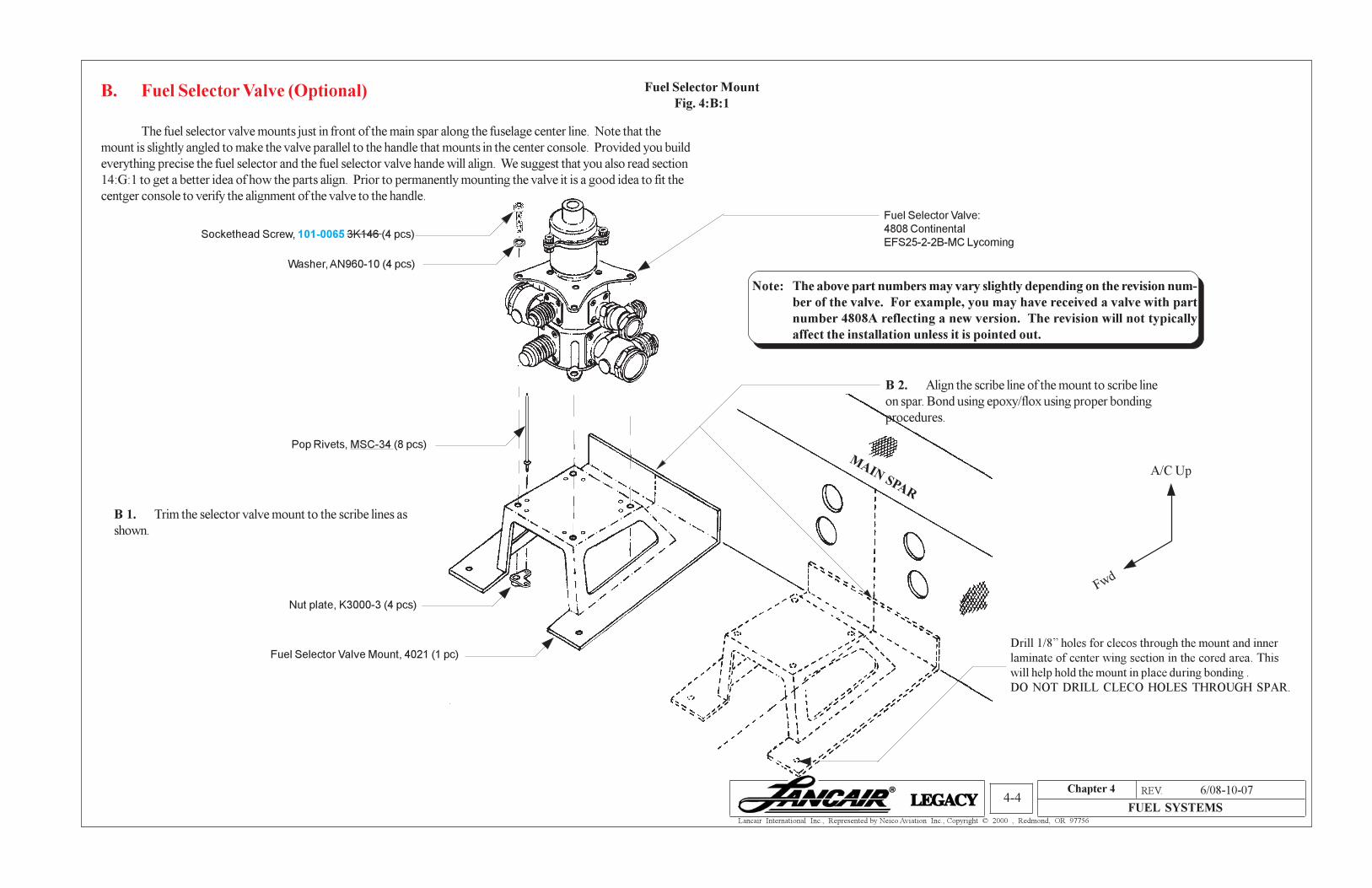
B. Fuel Selector Valve (Optional)
The fuel selector valve mounts just in front of the main spar along the fuselage center line. Note that the
mount is slightly angled to make the valve parallel to the handle that mounts in the center console. Provided you build
everything precise the fuel selector and the fuel selector valve hande will align. We suggest that you also read section
14:G:1 to get a better idea of how the parts align. Prior to permanently mounting the valve it is a good idea to fit the
centger console to verify the alignment of the valve to the handle.
Fuel Selector Mount
Fig. 4:B:1
B 1. Trim the selector valve mount to the scribe lines as
shown.
Sockethead Screw, 101-0065 3K146 (4 pcs)
Washer, AN960-10 (4 pcs)
B 2. Align the scribe line of the mount to scribe line
on spar. Bond using epoxy/flox using proper bonding
procedures.
Drill 1/8” holes for clecos through the mount and inner
laminate of center wing section in the cored area. This
will help hold the mount in place during bonding .
DO NOT DRILL CLECO HOLES THROUGH SPAR.
MAIN SPAR
Pop Rivets, MSC-34 (8 pcs)
Nut plate, K3000-3 (4 pcs)
Fuel Selector Valve Mount, 4021 (1 pc)
A/C Up
Fwd
Note: The above part numbers may vary slightly depending on the revision num-
ber of the valve. For example, you may have received a valve with part
number 4808A reflecting a new version. The revision will not typically
affect the installation unless it is pointed out.
Fuel Selector Valve:
4808 Continental
EFS25-2-2B-MC Lycoming
6/08-10-07

Chapter 4 REV. 0/02-15-02
FUEL SYSTEMS4-5
Lancair International Inc., Represented by Neico Aviation Inc., Copyright © 2000 , Redmond, OR 97756
Fuel Supply Lines for Center WingSection
(Exploded View)
Fig. 4:C:1
LEFT OUTBOARD WING
SECTION
Fuel pickup of outboard wing section
(pipe thread brass block, P/N FU3-2)
90° Bulkhead Fitting
AN833-8D (2 pcs)
90° Fitting with screen
FU7-2 (2 pcs)
CENTER WING SECTION
Check Nut, AN924-8D (4 pcs)
Straight Bulkhead Fitting
AN832-8D (2 pcs)
Shown with coupling, AN818-8D and
sleeve AN819-8D installed on each
end (connects to fuel selector valve)
WS-59 Rib
Suggested
passage hole for
fuel probe wires.
Access hole for the purpose of
securing the fuel supply lines.
Outboard Fwd
A/C Up
Shown with Coupling, AN818-8D and sleeve AN819-8D
installed on each end.
Enlarge hole at
scissor link rib as
required.
The line must have a
bend in it similar to
shown for wing flex.
Secure with adel clamp.
All fuel supply:
lines 5052-.500 x .035
sleeves AN819-8D
nuts AN818-8D
Inboard rib must be
aligned to complete the
supply line. See chapter
10 section B.
C. Fuel Supply Lines
We suggest installing all fittings and in general,
familiarize yourself with the system. Then
complete the center wing section fuel system
anytime after chapter 11.

Chapter 4 REV. 0/02-15-02
FUEL SYSTEMS4-6
Lancair International Inc., Represented by Neico Aviation Inc., Copyright © 2000 , Redmond, OR 97756
Fuel System Related Holes of WS 61.5 Rib
Fig. 4:C:2
A/C Up
2 1/2
”
1 1/2
”
3/4
”
1/2” dia. hole for fuel probe wires;
Suggestion: install a grommet for anti-
chafing
3/4” dia. hole clock the AN833-8D
approximately as shown.
Access hole for fuel
supply lines
LEFT SIDE SHOWN, LOOKING INBOARD
Center Main Spar Center Aft Spar
10 1/4
”
11 3/4
”
3 1/2
”
1 3/4
”
1 3/4
”
3.0”
Fwd
lower wing skin
2” dia.
2” dia. access hole for
return line.
2 1/4
” 1”
1 1/4
”
7/16
”
dia. hole (fuel return)

Chapter 4 REV. 0/02-15-02
FUEL SYSTEMS4-7
Lancair International Inc., Represented by Neico Aviation Inc., Copyright © 2000 , Redmond, OR 97756
Fuel Supply Lines through Over Center Link Rib
Fig . 4:C:3
A/C Up
Fwd
Outboard
Left Forward Over Center Link
Rib ShownVIEW LOOKING OUTBOARD
1 11/16
”
2 1/2
”
3 1/8
”
1”
1” dia.
Note: The above dimensions are approximate. Open up the holes as required.
Install antichafing on the fuel line, where the lines go through the rib.
1/09-18-02

Chapter 4 REV. 0/02-15-02
FUEL SYSTEMS4-8
Lancair International Inc., Represented by Neico Aviation Inc., Copyright © 2000 , Redmond, OR 97756
Fuel Vent Line Check
Valve, 545 (1 pc)NAV Antenna
D. Fuel Vent Line Check Valve
D 1. Install the fuel vent line check valve as shown. The red arrow must point towards the tank, which the
air flows into.
Installing Fuel Vent Line Check Valve
Fig. 4:D:1
2/06-30-04
A/C Up
Forward
OutboardAir flow direction
Chapter 4 REV. 0/02-15-02
FUEL SYSTEMS4-9
Lancair International Inc., Represented by Neico Aviation Inc., Copyright © 2000 , Redmond, OR 97756
*
*
*
*
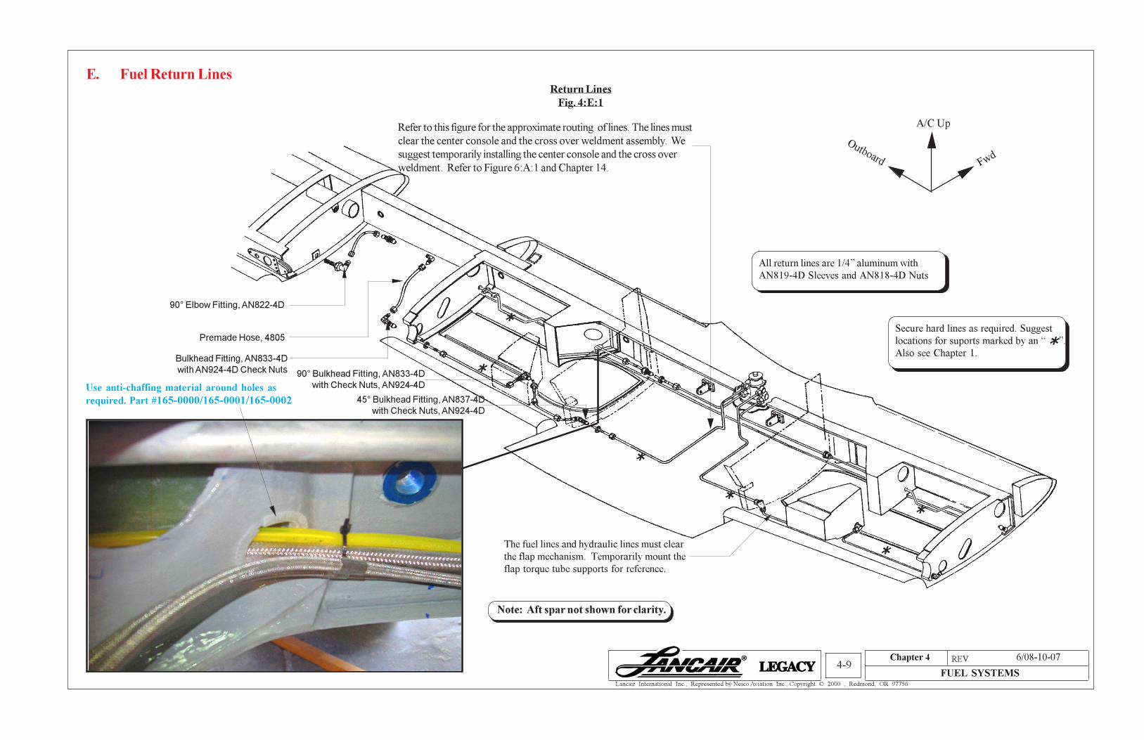
All return lines are 1/4” aluminum with
AN819-4D Sleeves and AN818-4D Nuts
Return Lines
Fig. 4:E:1
Outboard Fwd
A/C Up
90° Elbow Fitting, AN822-4D
Premade Hose, 4805
Bulkhead Fitting, AN833-4D
with AN924-4D Check Nuts 90° Bulkhead Fitting, AN833-4D
with Check Nuts, AN924-4D
45° Bulkhead Fitting, AN837-4D
with Check Nuts, AN924-4D
*
*
Refer to this figure for the approximate routing of lines. The lines must
clear the center console and the cross over weldment assembly. We
suggest temporarily installing the center console and the cross over
weldment. Refer to Figure 6:A:1 and Chapter 14.
Note: Aft spar not shown for clarity.
The fuel lines and hydraulic lines must clear
the flap mechanism. Temporarily mount the
flap torque tube supports for reference.
E. Fuel Return Lines
Secure hard lines as required. Suggest
locations for suports marked by an “ ”.
Also see Chapter 1.*
Use anti-chaffing material around holes as
required. Part #165-0000/165-0001/165-0002
6/08-10-07

Chapter 4 REV. 0/02-15-02
FUEL SYSTEMS4-10
Lancair International Inc., Represented by Neico Aviation Inc., Copyright © 2000 , Redmond, OR 97756
Fuel Pick Up, FU3-2
Fuel Return, F
U4
Fuel Probe
Outboard Fwd
A/C Up
F. Fuel Probe (Optional)
F 1. Lancair offers two options for the fuel probes. One is for Vision Micro Systems (VMS) and the other is from
Electronics International (EI). The installation is identical. Both systems are available through Lancair Avionics.
Fuel Probe Installation
Fig. 4:F:1
Fuel Probes VMS P/N: 3050010
Fuel Probes EI P/N: P-300-C-8
Note: The correct fuel probe length for the Lancair Legacy fuel tanks is 72”.
G. Fuel Boost Pump (Optional)
G 1. The type of fuel pump used depends on the type of engine installed. The Continental requires a two-stage
fuel pump while the Lycoming a single stage. Two- stage means that the pump has a low boost. Refer to the pilot
operating handbook for proper use.
G 2. The new, longer fuel pump mount needs to be cut from web. Adjust the length of the mount as necessary.
The piece holding the fuel pump can be either bonded or screwed to the other section of the mount. Refer to the
photograph for current installation method.
Fuel Boost Pump Installation
Fig. 4:G:1
The boost pump requires a vent to the
outside. Note the two vent ports on the lower
part of the cylindrical body. Either one can be
used for the vent and the other must be
plugged.
Fuel Boost Pump:
For 12V Continental 550 P/N 5455-00-1
For 12V Lycoming 540 P/N 5456-00-1
Elbow Fitting, 229-4-1
1/8” RED tygon tubing
3814-6
Secure each end with
tie-wrap.
Drill through the floor using a #10 drill bit.
Pot the piece in place using epoxy/flox.
Hose clamp
145-0008 5416K23
Plug, MS27769-D1
(included with pump)
Fuel Pump
Mount
4042
Nose gear tunnel
Make a small opening in the
fuel pump mount to thread the
clamp through.
2.85”
Warning: Apply antiseize on the threads of the aluminum fuel probe mount. Without
antiseize the fuel probe will cold weld to the aluminum fuel probe.
Fwd
A/C Up
Brass Splice,
22-4, (1 pc.)
Bond the fuel pump mount to the nose gear tunnel
using epoxy/flox.
6/08-10-07
Chapter 4 REV. 0/02-15-02
FUEL SYSTEMS4-11
Lancair International Inc., Represented by Neico Aviation Inc., Copyright © 2000 , Redmond, OR 97756
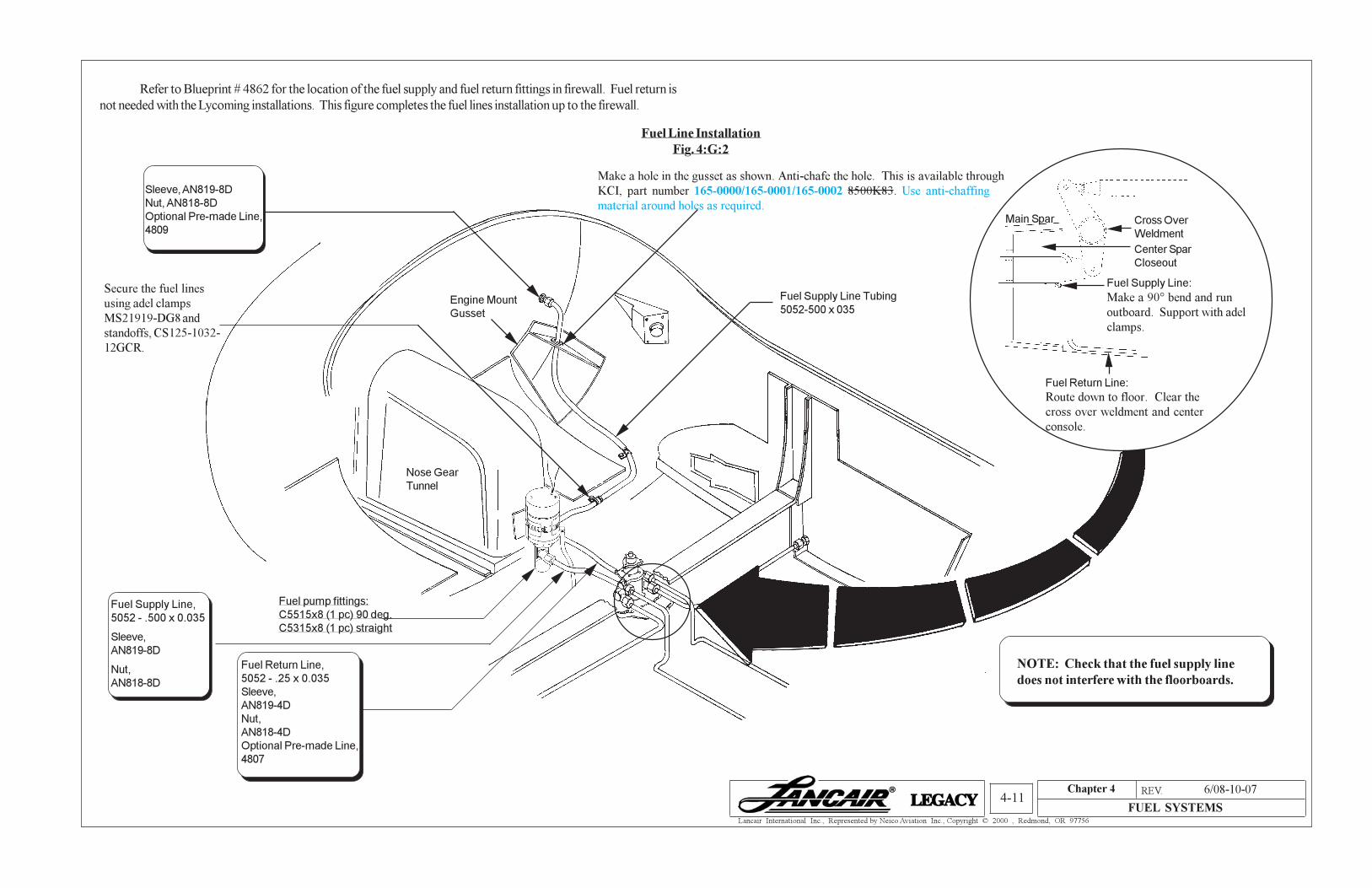
Fuel Line Installation
Fig. 4:G:2
Refer to Blueprint # 4862 for the location of the fuel supply and fuel return fittings in firewall. Fuel return is
not needed with the Lycoming installations. This figure completes the fuel lines installation up to the firewall.
Secure the fuel lines
using adel clamps
MS21919-DG8 and
standoffs, CS125-1032-
12GCR.
Fuel pump fittings:
C5515x8 (1 pc) 90 deg.
C5315x8 (1 pc) straight
Nose Gear
Tunnel
Engine Mount
Gusset
Make a hole in the gusset as shown. Anti-chafe the hole. This is available through
KCI, part number 165-0000/165-0001/165-0002 8500K83. Use anti-chaffing
material around holes as required.
Fuel Supply Line Tubing
5052-500 x 035
NOTE: Check that the fuel supply line
does not interfere with the floorboards.
Main Spar Cross Over
Weldment
Fuel Supply Line:
Make a 90° bend and run
outboard. Support with adel
clamps.
Fuel Return Line:
Route down to floor. Clear the
cross over weldment and center
console.
Center Spar
Closeout
Sleeve, AN819-8D
Nut, AN818-8D
Optional Pre-made Line,
4809
Fuel Return Line,
5052 - .25 x 0.035
Sleeve,
AN819-4D
Nut,
AN818-4D
Optional Pre-made Line,
4807
Fuel Supply Line,
5052 - .500 x 0.035
Sleeve,
AN819-8D
Nut,
AN818-8D
6/08-10-07
Chapter 4 REV. 0/02-15-02
FUEL SYSTEMS4-12
Lancair International Inc., Represented by Neico Aviation Inc., Copyright © 2000 , Redmond, OR 97756
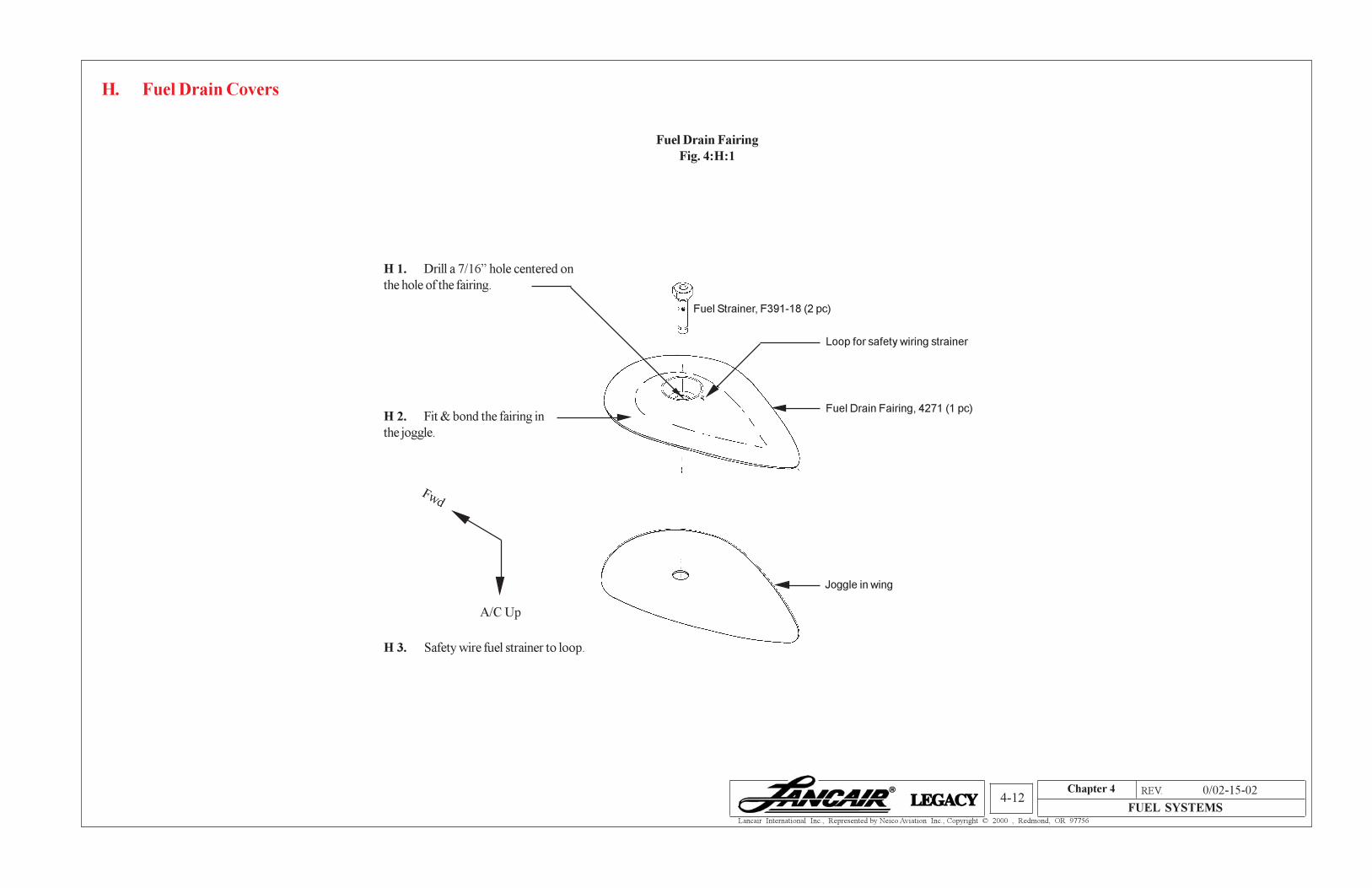
H. Fuel Drain Covers
Fuel Drain Fairing
Fig. 4:H:1
H 1. Drill a 7/16” hole centered on
the hole of the fairing.
Loop for safety wiring strainer
H 2. Fit & bond the fairing in
the joggle.
Fuel Strainer, F391-18 (2 pc)
Joggle in wing
H 3. Safety wire fuel strainer to loop.
Fuel Drain Fairing, 4271 (1 pc)
A/C Up
Fwd