Lee Duct Size by Dp100(Rev5)
11
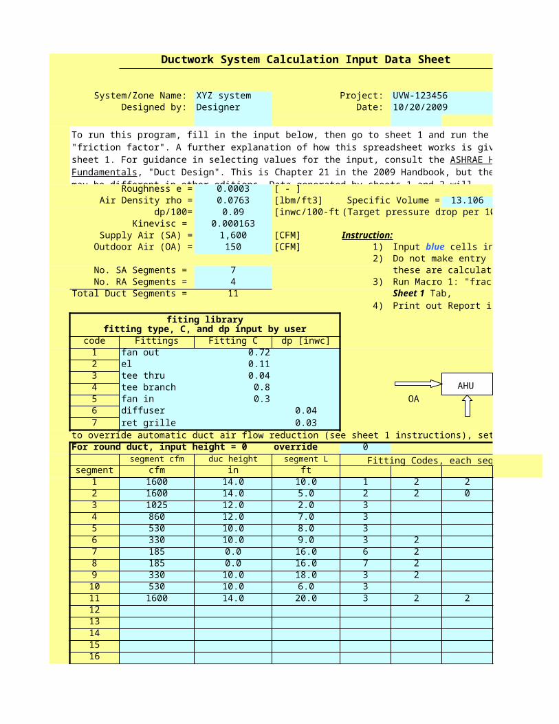
Ductwork System Calculation Input Data Sheet System/Zone Name: XYZ system Project: UVW-123456 Designed by: Designer Date: 10/20/2009 Roughness e = 0.0003 [ - ] Air Density rho = 0.0763 [lbm/ft3] Specific Volume = 13.106 dp/100= 0.09 [inwc/100-ft (Target pressure drop per 10 Kinevisc = 0.000163 Supply Air (SA) = 1,600 [CFM] Instruction: Outdoor Air (OA) = 150 [CFM] 1) 2) Do not make entry i No. SA Segments = 7 these are calculate No. RA Segments = 4 3) Run Macro 1: "fract Total Duct Segments = 11 4) fiting library fitting type, C, and dp input by user code Fittings Fitting C dp [inwc] 1 fan out 0.72 2 el 0.11 3 tee thru 0.04 4 tee branch 0.8 5 fan in 0.3 OA 6 diffuser 0.04 7 ret grille 0.03 to override automatic duct air flow reduction (see sheet 1 instructions), set For round duct, input height = 0 override 0 segment cfm duc height segment L Fitting Codes, each seg segment cfm in ft 1 1600 14.0 10.0 1 2 2 2 1600 14.0 5.0 2 2 0 3 1025 12.0 2.0 3 4 860 12.0 7.0 3 5 530 10.0 8.0 3 6 330 10.0 9.0 3 2 7 185 0.0 16.0 6 2 8 185 0.0 16.0 7 2 9 330 10.0 18.0 3 2 10 530 10.0 6.0 3 11 1600 14.0 20.0 3 2 2 12 13 14 15 16 To run this program, fill in the input below, then go to sheet 1 and run the "friction factor". A further explanation of how this spreadsheet works is giv sheet 1. For guidance in selecting values for the input, consult the ASHRAE H Fundamentals , "Duct Design". This is Chapter 21 in the 2009 Handbook, but the may be different in other editions. Data generated by sheets 1 and 2 will Input blue cells in Sheet 1 Tab, Print out Report in AHU
Transcript of Lee Duct Size by Dp100(Rev5)
Ductwork System Calculation Input Data Sheet
System/Zone Name: XYZ system Project: UVW-123456Designed by: Designer Date: 10/20/2009
Roughness e = 0.0003 [ - ]Air Density rho = 0.0763 [lbm/ft3] Specific Volume = 13.106
dp/100= 0.09 [inwc/100-ft] (Target pressure drop per 100')Kinevisc = 0.000163
Supply Air (SA) = 1,600 [CFM] Instruction:Outdoor Air (OA) = 150 [CFM] 1)
2) Do not make entry in gray cellsNo. SA Segments = 7 these are calculated cellsNo. RA Segments = 4 3) Run Macro 1: "fraction factor" in
Total Duct Segments = 114)
fiting libraryfitting type, C, and dp input by user
code Fittings Fitting C dp [inwc]1 fan out 0.722 el 0.113 tee thru 0.044 tee branch 0.85 fan in 0.3 OA SA6 diffuser 0.047 ret grille 0.03
to override automatic duct air flow reduction (see sheet 1 instructions), set override = 1For round duct, input height = 0 override 0
segment cfm duc height segment L Fitting Codes, each segmentsegment cfm in ft
1 1600 14.0 10.0 1 2 2 2 1600 14.0 5.0 2 2 0 03 1025 12.0 2.0 3 04 860 12.0 7.0 3 05 530 10.0 8.0 3 06 330 10.0 9.0 3 2 07 185 0.0 16.0 6 2 08 185 0.0 16.0 7 2 09 330 10.0 18.0 3 2
10 530 10.0 6.0 3 011 1600 14.0 20.0 3 2 2 51213141516
To run this program, fill in the input below, then go to sheet 1 and run the macro "friction factor". A further explanation of how this spreadsheet works is given on sheet 1. For guidance in selecting values for the input, consult the ASHRAE Handbook, Fundamentals, "Duct Design". This is Chapter 21 in the 2009 Handbook, but the chapter may be different in other editions. Data generated by sheets 1 and 2 will automatically be entered in the "Report" sheet.
Input blue cells in Input Tab,
Sheet 1 Tab,Print out Report in Report tab.
AHU
17181920212223242526272829
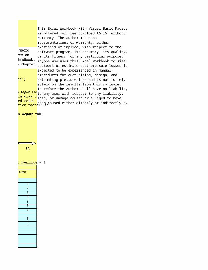
This Excel Workbook with Visual Basic Macros is offered for free download AS IS without warranty. The author makes no representations or warranty, either expressed or implied, with respect to the software program, its accuracy, its quality, or its fitness for any particular purpose. Anyone who uses this Excel Workbook to size ductwork or estimate duct pressure losses is expected to be experienced in manual procedures for duct sizing, design, and estimating pressure loss and is not to rely solely on the results from this software. Therefore the Author shall have no liability to any user with respect to any liability, loss, or damage caused or alleged to have been caused either directly or indirectly by its use. This includes but is not limited to interruption of service, loss of data, loss of consulting or anticipatory profits, or consequential damages from the use of this software.

Duct System Pressure Drop Calculation Result
System - Zone XYZ system
Project Number UVW-123456
Designer Designer
Date 10/20/2009
System/Zone Name: XYZ system Designed by: Designer Date:
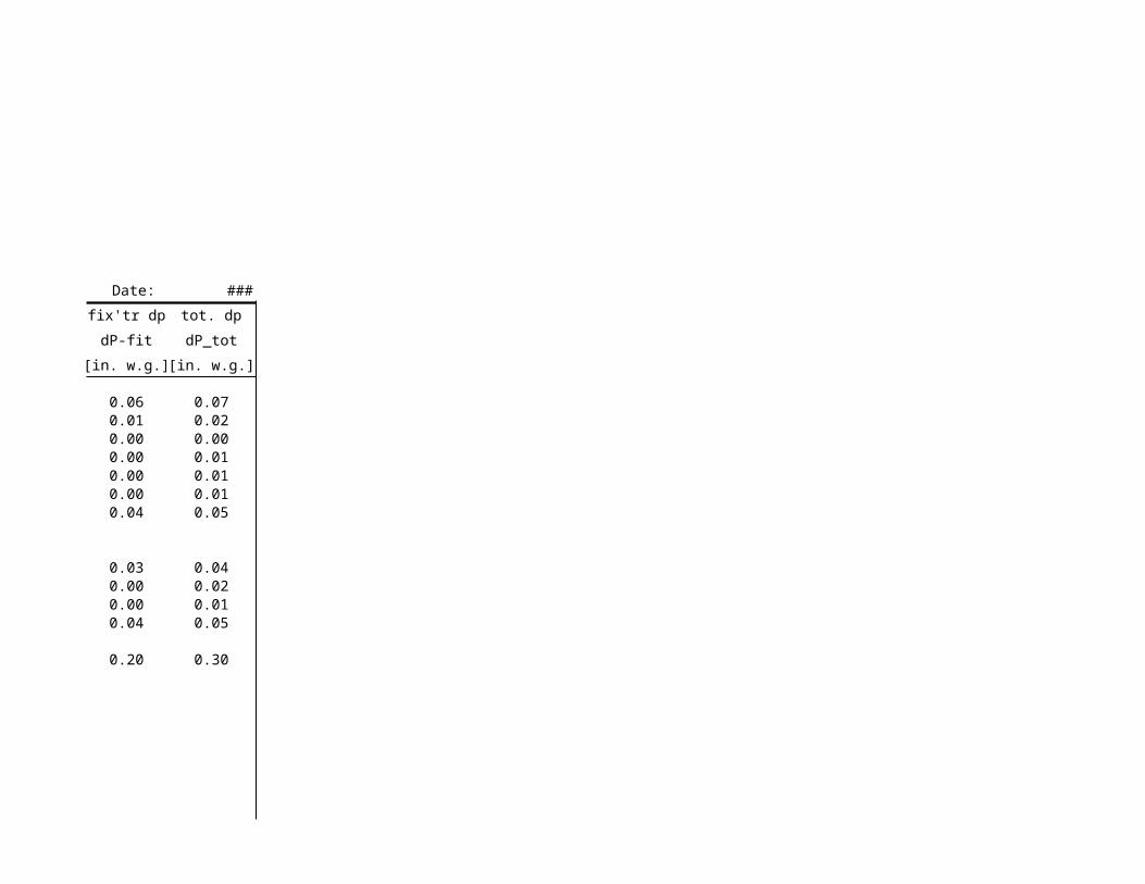
duct airflow height width dia velocity Re length duct dp dp/100' vel. dp fix'tr dp
leg Q H W D V Re L dP_duct dp/100' dP_v dP-fit
No. [cfm] [in] [in] [in] [fpm] [ - ] [ft] [in. w.g.] [iw/100'] [in. w.g.] [in. w.g.]supply duct
1 1,600 14 17 17 1,034 135,889 10.0 0.010 0.097 0.07 0.062 1,600 14 17 17 1,034 135,889 5.0 0.005 0.097 0.07 0.013 1,025 12 14 14 937 103,705 2.0 0.002 0.100 0.06 0.004 860 12 13 14 846 90,393 7.0 0.006 0.086 0.05 0.005 530 10 11 11 740 66,330 8.0 0.007 0.083 0.03 0.006 330 10 8 10 635 48,305 9.0 0.007 0.077 0.03 0.007 185 0 0 8 530 36,293 16.0 0.010 0.063 0.02 0.04
return duct8 168 0 0 8 480 32,891 16.0 0.008 0.053 0.01 0.039 299 10 7 9 661 46,575 18.0 0.016 0.091 0.03 0.00
10 480 10 10 11 737 63,081 6.0 0.005 0.088 0.03 0.0011 1,450 14 16 16 994 127,097 20.0 0.019 0.093 0.06 0.04
0.095 0.20


10/20/2009
tot. dp
dP_tot
[in. w.g.]
0.070.020.000.010.010.010.05
0.040.020.010.05
0.30

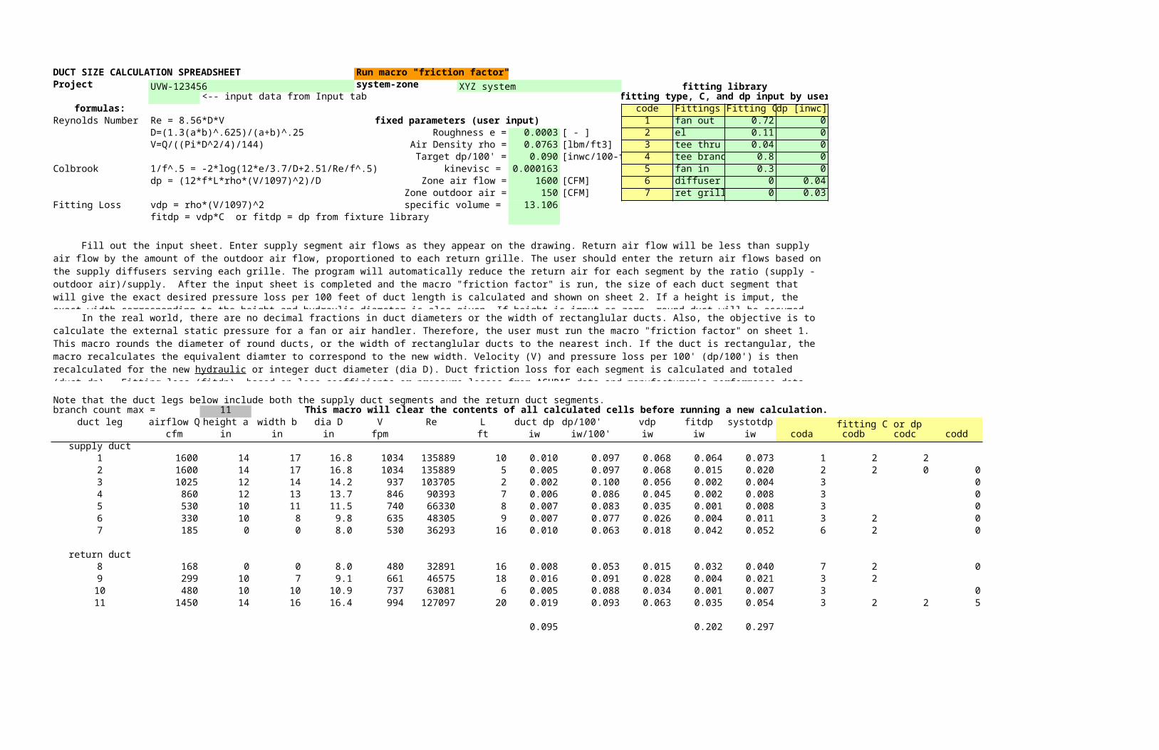
DUCT SIZE CALCULATION SPREADSHEET Run macro "friction factor"Project UVW-123456 system-zone XYZ system fitting library
<-- input data from Input tab fitting type, C, and dp input by userformulas: code Fittings Fitting C dp [inwc]
Reynolds Number Re = 8.56*D*V fixed parameters (user input) 1 fan out 0.72 0D=(1.3(a*b)^.625)/(a+b)^.25 Roughness e = 0.0003 [ - ] 2 el 0.11 0V=Q/((Pi*D^2/4)/144) Air Density rho = 0.0763 [lbm/ft3] 3 tee thru 0.04 0
Target dp/100' = 0.090 [inwc/100-ft] 4 tee branch 0.8 0Colbrook 1/f^.5 = -2*log(12*e/3.7/D+2.51/Re/f^.5) kinevisc = 0.000163 5 fan in 0.3 0
dp = (12*f*L*rho*(V/1097)^2)/D Zone air flow = 1600 [CFM] 6 diffuser 0 0.04Zone outdoor air = 150 [CFM] 7 ret grille 0 0.03
Fitting Loss vdp = rho*(V/1097)^2 specific volume = 13.106fitdp = vdp*C or fitdp = dp from fixture library
Note that the duct legs below include both the supply duct segments and the return duct segments.branch count max = 11 This macro will clear the contents of all calculated cells before running a new calculation.
duct leg airflow Q height a width b dia D V Re L duct dp dp/100' vdp fitdp systotdp fitting C or dpcfm in in in fpm ft iw iw/100' iw iw iw coda codb codc codd
supply duct1 1600 14 17 16.8 1034 135889 10 0.010 0.097 0.068 0.064 0.073 1 2 2 2 1600 14 17 16.8 1034 135889 5 0.005 0.097 0.068 0.015 0.020 2 2 0 03 1025 12 14 14.2 937 103705 2 0.002 0.100 0.056 0.002 0.004 3 04 860 12 13 13.7 846 90393 7 0.006 0.086 0.045 0.002 0.008 3 05 530 10 11 11.5 740 66330 8 0.007 0.083 0.035 0.001 0.008 3 06 330 10 8 9.8 635 48305 9 0.007 0.077 0.026 0.004 0.011 3 2 07 185 0 0 8.0 530 36293 16 0.010 0.063 0.018 0.042 0.052 6 2 0
return duct8 168 0 0 8.0 480 32891 16 0.008 0.053 0.015 0.032 0.040 7 2 09 299 10 7 9.1 661 46575 18 0.016 0.091 0.028 0.004 0.021 3 2
10 480 10 10 10.9 737 63081 6 0.005 0.088 0.034 0.001 0.007 3 011 1450 14 16 16.4 994 127097 20 0.019 0.093 0.063 0.035 0.054 3 2 2 5
0.095 0.202 0.297
Fill out the input sheet. Enter supply segment air flows as they appear on the drawing. Return air flow will be less than supply air flow by the amount of the outdoor air flow, proportioned to each return grille. The user should enter the return air flows based on the supply diffusers serving each grille. The program will automatically reduce the return air for each segment by the ratio (supply - outdoor air)/supply. After the input sheet is completed and the macro "friction factor" is run, the size of each duct segment that will give the exact desired pressure loss per 100 feet of duct length is calculated and shown on sheet 2. If a height is imput, the exact width corresponding to the height and hydraulic diameter is also given. If height is imput as zero, round duct will be assumed. There is no need for the user to reference sheet two except to verify results.
In the real world, there are no decimal fractions in duct diameters or the width of rectanglular ducts. Also, the objective is to calculate the external static pressure for a fan or air handler. Therefore, the user must run the macro "friction factor" on sheet 1. This macro rounds the diameter of round ducts, or the width of rectanglular ducts to the nearest inch. If the duct is rectangular, the macro recalculates the equivalent diamter to correspond to the new width. Velocity (V) and pressure loss per 100' (dp/100') is then recalculated for the new hydraulic or integer duct diameter (dia D). Duct friction loss for each segment is calculated and totaled (duct dp). Fitting loss (fitdp), based on loss coefficients or pressure losses from ASHRAE data and manufacturer's performance data, is calculated based on the fittings input from the sheet "Input". Finally, the external static pressure (systotdp) is calculated and totaled.
ProjectSystem-Zone green cell: input data from Input sheetcalculation date shaded cell: calculated by UDF or formula - do not make entry
Duct Size and Rectangular/round duct conversion
supply air flow = 1600.0 cfm dp100 = 0.090 outdoor air flow = 150.0 oacfm e = 0.0003
return air flow = 1450.0 rcfm rho = 0.0763 spvol= 13.106kinevisc = 0.000163
subcountmax = 7 supply duct segments return segments =D=(1.3(a*b)^.625)/(a+b)^.25 Curve fit of dia for dp100=.095 (first guess): D=alog(.38352*log(cfm) + .00864)
airflow height dia width dp100 L cfm in in in iw/100' ft
1,600.0 14.0 #VALUE! #VALUE! #VALUE! 10.01,600.0 14.0 #VALUE! #VALUE! #VALUE! 5.01,025.0 12.0 #VALUE! #VALUE! #VALUE! 2.0860.0 12.0 #VALUE! #VALUE! #VALUE! 7.0530.0 10.0 #VALUE! #VALUE! #VALUE! 8.0330.0 10.0 #VALUE! #VALUE! #VALUE! 9.0185.0 0.0 #VALUE! 0.0 #VALUE! 16.0167.7 0.0 #VALUE! 0.0 #VALUE! 16.0299.1 10.0 #VALUE! #VALUE! #VALUE! 18.0480.3 10.0 #VALUE! #VALUE! #VALUE! 6.0
1,450.0 14.0 #VALUE! #VALUE! #VALUE! 20.0

shaded cell: calculated by UDF or formula - do not make entry
return segments = 4D=alog(.38352*log(cfm) + .00864)
module 1 friction factor macromodule 111 fcalc UDFmodule 12 AirCap UDFmodule 21 Air Dia UDFmodule 31 Wcalc UDFmodule 51 AirPd UDF