LED Moving Wash/Beam Light with Halo Model: Impstar 40 000-255 White LED Dimmer0%~ 100% 10 000-255...
12
1 Model: Impstar 40 LED Moving Wash/Beam Light with Halo
-
Upload
trinhduong -
Category
Documents
-
view
214 -
download
1
Transcript of LED Moving Wash/Beam Light with Halo Model: Impstar 40 000-255 White LED Dimmer0%~ 100% 10 000-255...

1
Model: Impstar 40
LED Moving Wash/Beam Light with Halo

2
IMPORTANT SAFETY INFORMATION
Please read these instructions carefully before use and retain for future reference.
• When using electrical appliances basic safety precautions should always be followed.
• Check the product before use for any damage. Should you notice any damage on the cable or casing, do not use.
• Check that the voltage indicated on the rating plate corresponds with that of the local network before connecting the product to the mains power supply.
• Keep this product away from rain and moisture.• Caution: Never look directly into the light source.• Always disconnect from the mains when the product is not in use or before
cleaning.• Make sure there are no flammable materials close to the unit while operating.• Do not operate or store in an environment of high humidity or where moisture may
enter the product as this can reduce insulation and lead to electric shock.• Do not connect the product to a dimmer pack.• Never carry the fixture solely by its head.• The LED lamps in this product are not replaceable.• Refer all servicing and repair work to qualified personnel.
Safety Information for Installation and Operation:• When installing, make sure that the product is not exposed to extreme heat,
moisture or dust. • If you’re using a smoke machine, make sure that the product is never exposed to
the direct smoke jet and is installed at least 0.5m away.• The maximum ambient temperature is 40°C (104°F). Do not operate the product in
temperatures higher than this.• The relative humidity must not exceed 50% with an ambient temperature of 45°C.• The minimum distance between the light-output and the illuminated surface must
be more than 0.5m.• This product is allowed to be installed via a mounting bracket. In order to have
sufficient ventilation, leave 50cm of free space around the device. Ensure no ventilation slots are blocked.
• A secondary means of suspension must be provided, such that in the event of a failure of the primary suspension, no part of the luminaire can fall.
• The housing must not touch any surrounding surfaces or objects. • The operator must make sure that safety related matters are observed and that
the installation is approved by a qualified installer before taking into operation for the first time.
• Always disconnect from the power source before servicing or replacing the fuse and be sure to replace with the same fuse size and type.
3
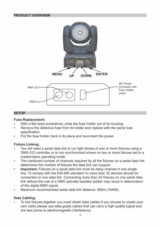
PRODUCT OVERVIEW
SETUP
Fuse Replacement:• With a flat head screwdriver, prise the fuse holder out of its housing. • Remove the defective fuse from its holder and replace with the same fuse
specification.• Put the fuse holder back in its place and reconnect the power.
Fixture Linking:• You will need a serial data link to run light shows of one or more fixtures using a
DMX-512 controller or to run synchronized shows on two or more fixtures set to a master/slave operating mode.
• The combined number of channels required by all the fixtures on a serial data link determines the number of fixtures the data link can support.
• Important: Fixtures on a serial data link must be daisy chained in one single line. To comply with the EIA-485 standard no more than 32 devices should be connected on one data link. Connecting more than 32 fixtures on one serial data link without the use of a DMX optically-isolated splitter may result in deterioration of the digital DMX signal.
• Maximum recommended serial data link distance: 500m (1640ft).
Data Cabling:• To link fixtures together you must obtain data cables.If you choose to create your
own cable please use data-grade cables that can carry a high quality signal and are less prone to electromagnetic interference.
MENU UP DOWN ENTER
IEC PowerConnector withFuse Holder(rear)
DMX In
DMX Out

4
CABLE CONNECTIONS
• Cabling must have a male XLR connector on one end and a female XLR connector on the other end.
• Caution: Do not allow contact between the common and the fixture’s chassis ground. Grounding the common can cause a ground loop, and your fixture may perform erratically. Test cables with an ohm meter to verify correct polarity and to make sure the pins are not grounded or shorted to the shield or each other.
3-PIN TO 5-PIN CONVERSION CHART
• Note: If you use a controller with a 5pin DMX output connector, you will need to use a 5-pin to 3-pin adaptor.
Conductor 3-pin female (output) 5-pin male (input)Ground/Shield Pin 1 Pin 1Data (-) signal Pin 2 Pin 2Data (+) signal Pin 3 Pin 3
Termination reduces signal errors. To avoid signal transmission problems and interference, it is always advisable to connect a DMX signal terminator to the output of the final fixture in the chain.
DMX Data Cable:• Use a Belden 9841 or equivalent cable that meets the specifications for EIA RS-
485 applications. The cable will have the following characteristics: - 2-conductor trwitsed pair plus a shield - Maximum capacitance between conductors - 30pF/ft - Maximum capacitance between conductor and shield - 55pF/ft - Maximum resistance of 20Ω / 1000ft - Nominal impedance 100-140Ω.
• Standard microphone cable cannot transmit DMX data reliably over long distances.
SETUP

5
SETTING UP A DMX SERIAL DATA LINK
• Connect the (male) 3-pin connector side of the DMX cable to the output (female) 3-pin connector of the controller.
• Connect the end of the cable coming from the controller, which will have a (female) 3-pin connector, to the input connecotr of the next fixture consisting of (male) 3-pin connector.
• Then proceed to connect from the output as stated above to the input of the following fixture and so on.
MASTER/SLAVE FIXTURE LINKING
• Connect the (male) 3-pin connector side of the DMX cable to the output (female) 3-pin connector of the first fixture.
• Connect the end of the cable coming from the first fixture, which will have a (female) 3-pin connector, to the input connector of the next fixture consisting of a (male) 3-pin connector.
• Then proceed to connect from the output as stated above to the input of the following fixture and so on.
• Often, the setup for Master-Slave and Standalone operation requires that the first fixture in the chain is initialised for this purpose via either the settings in the control panel, or DIP switches.
• Secondly, the fixtures that follow may also require a slave setting. See “Operating Instructions” on page 6 for guidance on this type of setup.
MOUNTING
Orientation:• This fixture may be mounted on a suitable base in any position provided there is
adequate room for ventilation.
6
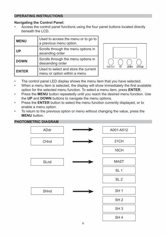
OPERATING INSTRUCTIONS
Navigating the Control Panel:• Access the control panel functions using the four panel buttons located directly
beneath the LCD.
MENU Used to access the menu or to go to a previous menu option.
UP Scrolls through the menu options in ascending order
DOWN Scrolls through the menu options in descending order
ENTER Used to select and store the current menu or option within a menu
• The control panel LED display shows the menu item that you have selected.• When a menu item is selected, the display will show immediately the first available
option for the selected menu function. To select a menu item, press ENTER.• Press the MENU button repeatedly until you reach the desired menu function. Use
the UP and DOWN buttons to navigate the menu options.• Press the ENTER button to select the menu function currently displayed, or to
enable a menu option.• To return to the previous option or menu without changing the value, press the
MENU button.
PHOTOMETRIC DIAGRAM
ADdr
CHnd
16CH
21CH
A001-A512
SHnd
SLnd MAST
SL 2
SL 1
SH 1
SH 3
SH 2
SH 4
MENU

7
SoUn
1-4AuTo
on
Off
0-100
on
off
no
YES
no
YES
YES
SeNs
Led
DiSp
Pan
Tilt
no
Test
Hour
vEr
rSEt
Performs mode test sequence
Displays hours usage
Displays software version
Resets to default

8
USER CONFIGURATION
SERVICE FUNCTIONSTo reset the unit:• Press the MENU button until the display shows “rSet”. Press ENTER to confirm.To test the operating functions:• Press MENU until “teSt” is displayed and the sequece will commence.
OPERATION MODE• Press the MENU button and the display shows each option in sequence, then
press ENTER and the LCD will show modes for you to choose.• Use the UP/DOWN buttons to set the desired inversion, then press ENTER to
confirm.
To set the DMX channel configuration:• Press the MENU button until it shows “ChNd”, then press ENTER and the LCD will
show “16CH” or “21CH”.• Use the UP/DOWN buttons to set the desired channel mode and press ENTER to
confirm.• Choose a unit to function as the Master, then select one of the modes as an auto
running programme.• Finally, chain the units together using DMX cable, the required speed mode can be
the Master one’s programming. The other units are set to the same DMX Address.Set Master/Slave Mode:• Press MODE until “SlNd” is displayed,• Press ENTER to chose “master”, “slave 1” or “Slave 2” modes, Press ENTER to
set the mode. This mode will allow you to link up to 32 units together without a controller.
• Use standard DMX cables to daisy chain your units together via the DMX connector on the rear of the units.
• Proper performance it may be necessary to use a terminator at the last fixture.AUTO Speed Mode:• This mode allows a single unit to run one of four factory installed programme in a
range of 9 speeds.Sound Mode:• Press MODE until “SeNs” is displayed.
Press ENTER to choose sensitivity of response by use of the UP and DOWN buttons. Press ENTER to set the desired level.
To set the PAN to inverting or non-inverting:• Press the MODE button until it shows “PaN”, then press ENTER and the LCD will
show “OFF” or “ON”.• Use the UP/DOWN buttons to set the desired mode and press ENTER to confirm.To set the Tilt to inverting or non-inverting:• Press the MODE button until it shows “TiLt”, then press ENTER and the LCD will
show “OFF” or “ON”.• Use the UP/DOWN buttons to set the desired mode and press ENTER to confirm.LED Mode:• Press MODE until “Led” is displayed.
Press ENTER and then use the UP/DOWN buttons to set “ON” or “OFF” The LED display will turn off after a time unless a button is pressed.

9
DMX MODE• This mode allows the unit to be controlled by any universal DMX controller.• Press MENU until “Addr” is displayed and press ENTER.• Press UP or DOWN to select an address then press ENTER to set.DMX CHANNEL VALUES (16 CHANNELS)
To display the hours the lamp has been operating:• Press the MENU button until “hour” is displayed• Press ENTER and the total hours usage to date will be shown.To display the software revision version:• Press MENU until “Ver” is diaplayed.• Press ENTER and the current version is displayed.
Channel DMX Value Function1 000-255 Pan 0°~ 540°2 000-255 Tilt 0°~ 210°3 000-255 Pan&Tilt Speed from fast to slow4 000-255 LED Dimmer0%~ 100%5 000-008 No function
009-255 LED Strobe slow to fast6 000-255 RED LED Dimmer0%~ 100%7 000-255 Green LED Dimmer0%~ 100%8 000-255 Blue LED Dimmer0%~ 100%9 000-255 White LED Dimmer0%~ 100%
10 000-255 5050 SMD Dimmer0%~ 100%11 000-008 No function
009-255 5050 SMD Strobe slow to fast12 000-010 No Function
011-044 5050 SMD section 1 Red045-079 5050 SMD section 1 Green080-114 5050 SMD section 1 Blue115-149 5050 SMD section 1 Red mix Green150-184 5050 SMD section 1 Red mix Blue185-219 5050 SMD section 1 Green mix Blue220-255 5050 SMD section 1 RGB
13 000-010 No Function011-044 5050 SMD section 2 Red045-079 5050 SMD section 2 Green080-114 5050 SMD section 2 Blue115-149 5050 SMD section 2 Red mix Green
10
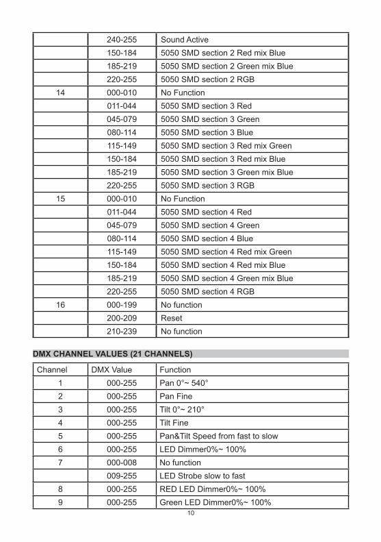
240-255 Sound Active150-184 5050 SMD section 2 Red mix Blue185-219 5050 SMD section 2 Green mix Blue220-255 5050 SMD section 2 RGB
14 000-010 No Function011-044 5050 SMD section 3 Red045-079 5050 SMD section 3 Green080-114 5050 SMD section 3 Blue115-149 5050 SMD section 3 Red mix Green150-184 5050 SMD section 3 Red mix Blue185-219 5050 SMD section 3 Green mix Blue220-255 5050 SMD section 3 RGB
15 000-010 No Function011-044 5050 SMD section 4 Red045-079 5050 SMD section 4 Green080-114 5050 SMD section 4 Blue115-149 5050 SMD section 4 Red mix Green150-184 5050 SMD section 4 Red mix Blue185-219 5050 SMD section 4 Green mix Blue220-255 5050 SMD section 4 RGB
16 000-199 No function200-209 Reset210-239 No function
DMX CHANNEL VALUES (21 CHANNELS)
Channel DMX Value Function1 000-255 Pan 0°~ 540°2 000-255 Pan Fine3 000-255 Tilt 0°~ 210°4 000-255 Tilt Fine5 000-255 Pan&Tilt Speed from fast to slow6 000-255 LED Dimmer0%~ 100%7 000-008 No function
009-255 LED Strobe slow to fast8 000-255 RED LED Dimmer0%~ 100%9 000-255 Green LED Dimmer0%~ 100%

11
10 000-255 Blue LED Dimmer0%~ 100%11 000-255 White LED Dimmer0%~ 100%12 000-255 5050 SMD Dimmer0%~ 100%13 000-008 No function
009-255 5050 SMD Strobe slow to fast14 000-255 5050 SMD RED Dimmer0%~ 100%15 000-255 5050 SMD Green Dimmer0%~ 100%16 000-255 5050 SMD Blue Dimmer0%~ 100%17 000-010 No Function
011-044 5050 SMD section 1 Red045-079 5050 SMD section 1 Green080-114 5050 SMD section 1 Blue115-149 5050 SMD section 1 Red mix Green150-184 5050 SMD section 1 Red mix Blue185-219 5050 SMD section 1 Green mix Blue220-255 5050 SMD section 1 RGB
18 000-010 No Function011-044 5050 SMD section 2 Red045-079 5050 SMD section 2 Green080-114 5050 SMD section 2 Blue115-149 5050 SMD section 2 Red mix Green150-184 5050 SMD section 2 Red mix Blue185-219 5050 SMD section 2 Green mix Blue220-255 5050 SMD section 2 RGB
19 000-010 No Function011-044 5050 SMD section 3 Red045-079 5050 SMD section 3 Green080-114 5050 SMD section 3 Blue115-149 5050 SMD section 3 Red mix Green150-184 5050 SMD section 3 Red mix Blue185-219 5050 SMD section 3 Green mix Blue220-255 5050 SMD section 3 RGB
20 000-010 No Function011-044 5050 SMD section 4 Red045-079 5050 SMD section 4 Green080-114 5050 SMD section 4 Blue

12
INFORMATION ON WASTE DISPOSAL FOR CONSUMERS OF ELECTRICAL & ELECTRONIC EQUIPMENT.When this product has reached the end of its life it must be treated as Waste Electrical & Electronic Equipment (WEEE). Any WEEE marked products must not be mixed with general household waste, but kept separate for the treatment, recovery and recycling of the materials used. Contact your local authority for details of recycling schemes in your area.
Made in China. PR2 9PPMan Rev 1.0
CLEANING & MAINTENANCE
• Disconnect from the mains before starting the maintenance operation.• Frequent cleaning is recommended. Use a soft lint-free moistened cloth. • Do not use any chemicals, abrasives or solvents that could damage the device.• There are no user-serviceable parts in this product. Refer all servicing to qualified
personnel.
SPECIFICATION
Voltage AC 100-240V 50-60HzPower Consumption 60W
Light source 40W RGBW LED WITH 5050 SMD 3in1DMX mode 16/21 ChannelControl DMX 512, Master-slave, Auto, SoundDisplay Digital displayRotating angle X axis: 540°, Y axis: 210°Function 4 internal program, sound controlled by DMX 512Work environment 10°C - 40°CDimension 155 x 160 x 280mmWeight 4.0kg
115-149 5050 SMD section 4 Red mix Green150-184 5050 SMD section 4 Red mix Blue185-219 5050 SMD section 4 Green mix Blue220-255 5050 SMD section 4 RGB
21 000-199 No function200-209 Reset210-239 No function240-255 Sound Active