LED HIGH POWER - Index - Liteonoptoelectronics.liteon.com/upload/media/light/Datasheet...06 LED HIGH...
24
1 LED HIGH POWER C08-M Product Series BNC-OD-C131/A4 Created Date : 05/26/2007 Revison : 1.01, 05/26/2008 LED HIGH POWER C08 Product Series Data Sheet Created Date: 03 / 08 / 2013 Revision: 1.3, 03 / 15 / 2013 LED HIGH POWER C08-M Product Series Data Sheet Created Date: 03 / 01 / 2014 Revision: 0.3, 06 / 17 / 2014
Transcript of LED HIGH POWER - Index - Liteonoptoelectronics.liteon.com/upload/media/light/Datasheet...06 LED HIGH...

1
LED HIGH POWER C08-M Product Series
BNC-OD-C131/A4 Created Date : 05/26/2007 Revison : 1.01, 05/26/2008
LED HIGH POWER C08 Product Series Data Sheet Created Date: 03 / 08 / 2013 Revision: 1.3, 03 / 15 / 2013
LED HIGH POWER C08-M Product Series Data Sheet Created Date: 03 / 01 / 2014 Revision: 0.3, 06 / 17 / 2014
02
LED HIGH POWER C08-M Product Series
BNC-OD-C131/A4 Created Date: 03/01/2014 Revision: 0.3, 06/17/2014
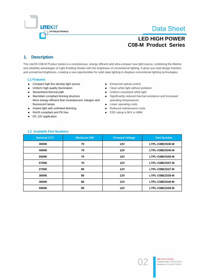
1. Description
The LiteON C08-M Product series is a revolutionary, energy efficient and ultra-compact new light source, combining the lifetime and reliability advantages of Light Emitting Diodes with the brightness of conventional lighting. It gives you total design freedom and unmatched brightness, creating a new opportunities for solid state lighting to displace conventional lighting technologies.
1.1 Features � Compact high flux density light source � Uniform high quality illumination � Streamlined thermal path � MacAdam compliant binning structure
More energy efficient than incandescent, halogen and fluorescent lamps
� Instant light with unlimited dimming � RoHS compliant and Pb free � DC 12V application
� Enhanced optical control � Clean white light without pixilation � Uniform consistent white light � Significantly reduced thermal resistance and increased
operating temperatures � Lower operating costs � Reduced maintenance costs � ESD rating is 8KV in HBM
1.2 Available Part Numbers
Nominal CCT Minimum CRI Forward Voltage Part Number
3000K 70 12V LTPL-C08EXS30-M
4000K 70 12V LTPL-C08EXS40-M
5000K 70 12V LTPL-C08EXS50-M
5700K 70 12V LTPL-C08EXS57-M
2700K 80 12V LTPL-C08EZS27-M
3000K 80 12V LTPL-C08EZS30-M
4000K 80 12V LTPL-C08EZS40-M
5000K 80 12V LTPL-C08EZS50-M
03
LED HIGH POWER C08-M Product Series
BNC-OD-C131/A4 Created Date: 03/01/2014 Revision: 0.3, 06/17/2014
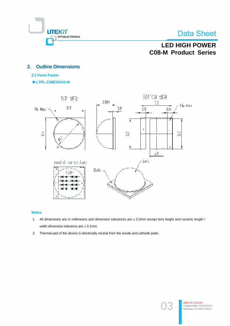
2. Outline Dimensions
2.1 Form Factor
� LTPL-C08EXXXX-M
Notes
1. All dimensions are in millimeters and dimension tolerances are ± 0.2mm except lens height and ceramic length /
width dimension tolerance are ± 0.1mm.
2. Thermal pad of the device is electrically neutral from the anode and cathode pads.

04
LED HIGH POWER C08-M Product Series
BNC-OD-C131/A4 Created Date: 03/01/2014 Revision: 0.3, 06/17/2014
3. Rating and Characteristics
3.1 Absolute Maximum Ratings at Ta=25°C.
Parameter Symbol Rating Unit
Power Dissipation Po 10 W
DC Forward Current IF 800 mA
ESD Sensitivity VB 8 kV
Junction Temperature Tj 125 °C
Thermal Resistance, Junction-Case Rth, J-C 3.3 °C / W
Operating Temperature Range Topr -40~+85 °C
Storage Temperature Range Tstg -55~+100 °C
Notes 1. The pulse mode condition is 1 KHz with 0.1msec pulse width.. 2. Forbid to operating at reverse voltage condition 3. ESD spec is reference to AEC-Q101-001 HBM. 4. The unit of Rth is °C/W electrical. 5. Thermal resistance measurement tolerance is ± 10%

05
LED HIGH POWER C08-M Product Series
BNC-OD-C131/A4 Created Date: 03/01/2014 Revision: 0.3, 06/17/2014
3.2 Electro-Optical Characteristics
� LTPL-C08EXXXX-M
Nominal CCT
Minimum CRI
Current (mA)
Typ. VF (V) @25°°°°C
Typ. Flux(lm) @25°°°°C
Typ. VF (V) @85°°°°C
Typ. Flux(lm) @85°°°°C
Eff.(lm/W) @25°°°°C
Eff.(lm/W) @85°°°°C
3000K 70 700 12.5 1055 12.1 939 121 111
4000K 70 700 12.5 1074 12.1 956 123 113
5000K 70 700 12.5 1084 12.1 965 124 114
5700K 70 700 12.5 1086 12.1 967 124 114
2700K 80 700 12.5 952 12.1 847 109 100
3000K 80 700 12.5 1005 12.1 894 115 105
4000K 80 700 12.5 1023 12.1 910 117 107
5000K 80 700 12.5 1032 12.1 919 118 108
Notes 1. All of the VF value are typical and the real bin range please refer page 10 ”VF Binning Parameter”. 2. All of the Flux value are typical and the real Bin range please refer page 9~10 ”Flux Binning Parameter”. 3. Tolerance of Flux is ±7%, Tolerance of VF is ±3%, tolerance of CCx/CCy is ±0.01, tolerance of CRI is ±3. 4. LEDs are lighted up and measured with externally parallel connecting leads of LED. 5. Typical viewing angle is 130deg.
06
LED HIGH POWER C08-M Product Series
BNC-OD-C131/A4 Created Date: 03/01/2014 Revision: 0.3, 06/17/2014
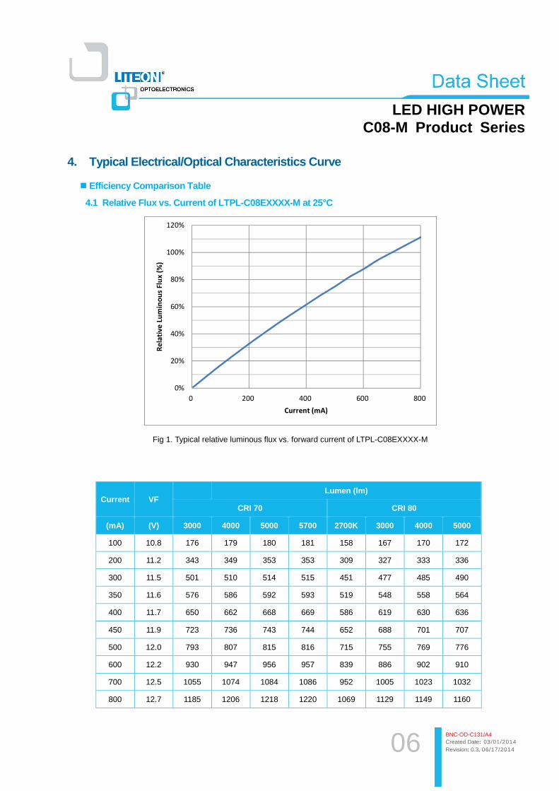
4. Typical Electrical/Optical Characteristics Curve
� Efficiency Comparison Table
4.1 Relative Flux vs. Current of LTPL-C08EXXXX-M at 25°C
0%
20%
40%
60%
80%
100%
120%
0 200 400 600 800
Re
lati
ve
Lu
min
ou
s F
lux (
%)
Current (mA)
Fig 1. Typical relative luminous flux vs. forward current of LTPL-C08EXXXX-M
Current VF Lumen (lm)
CRI 70 CRI 80
(mA) (V) 3000 4000 5000 5700 2700K 3000 4000 5000
100 10.8 176 179 180 181 158 167 170 172
200 11.2 343 349 353 353 309 327 333 336
300 11.5 501 510 514 515 451 477 485 490
350 11.6 576 586 592 593 519 548 558 564
400 11.7 650 662 668 669 586 619 630 636
450 11.9 723 736 743 744 652 688 701 707
500 12.0 793 807 815 816 715 755 769 776
600 12.2 930 947 956 957 839 886 902 910
700 12.5 1055 1074 1084 1086 952 1005 1023 1032
800 12.7 1185 1206 1218 1220 1069 1129 1149 1160
07
LED HIGH POWER C08-M Product Series
BNC-OD-C131/A4 Created Date: 03/01/2014 Revision: 0.3, 06/17/2014
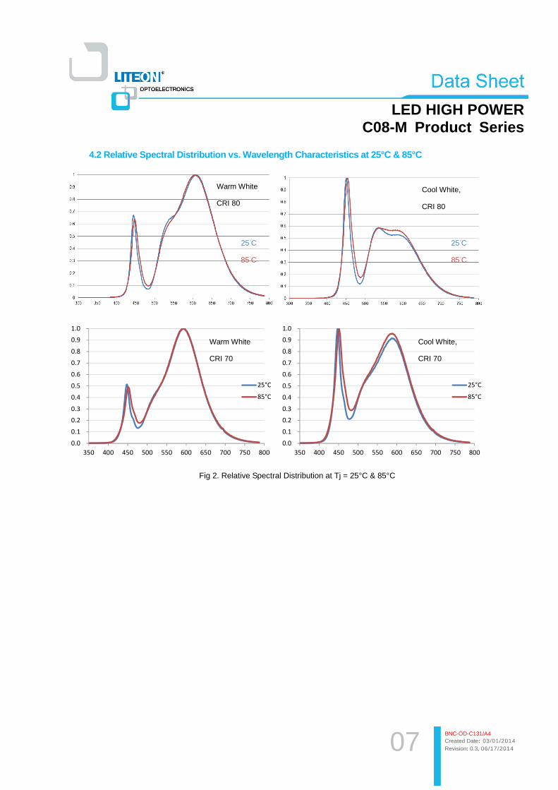
4.2 Relative Spectral Distribution vs. Wavelength C haracteristics at 25°C & 85°C
0.0
0.1
0.2
0.3
0.4
0.5
0.6
0.7
0.8
0.9
1.0
350 400 450 500 550 600 650 700 750 800
25°C
85°C
0.0
0.1
0.2
0.3
0.4
0.5
0.6
0.7
0.8
0.9
1.0
350 400 450 500 550 600 650 700 750 800
25°C
85°C
Fig 2. Relative Spectral Distribution at Tj = 25°C & 85°C
Warm White
CRI 80
Cool White,
CRI 80
25°C
85°C
25°C
85°C
Warm White
CRI 70
Cool White,
CRI 70
08
LED HIGH POWER C08-M Product Series
BNC-OD-C131/A4 Created Date: 03/01/2014 Revision: 0.3, 06/17/2014
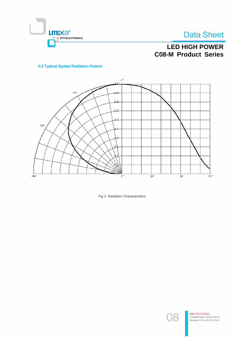
4.3 Typical Spatial Radiation Pattern
Fig 3. Radiation Characteristics

09
LED HIGH POWER C08-M Product Series
BNC-OD-C131/A4 Created Date: 03/01/2014 Revision: 0.3, 06/17/2014
4.4 Forward Current vs. Forward Voltage at 25°C
0
100
200
300
400
500
600
700
800
900
10.0 10.5 11.0 11.5 12.0 12.5 13.0
Cu
rre
nt
(mA
)
Voltage (V)
Fig 4. Forward Current vs. Forward Voltage of LTPL-C08EXXXX-M
4.5 Maximum Forward Current vs. Ambient Temperature
0
100
200
300
400
500
600
700
800
900
0 20 40 60 80 100 120 140
Fo
rwa
rd C
urr
en
t (m
A)
Ambient Temperature (°C)
Fig 5. Forward Current Degrading Curve of LTPL-C08EXXXX-M

010
LED HIGH POWER C08-M Product Series
BNC-OD-C131/A4 Created Date: 03/01/2014 Revision: 0.3, 06/17/2014
5. VF Bin Definition
5.1 Forward Voltage Binning Parameter at 25°C
� LTPL-C08EXXXX-M
Parameter Bin Symbol Min Max Unit Condition
Forward Voltage DC1 VF 11.5 12.0 V IF = 700mA
Forward Voltage DC2 VF 12.0 12.5 V IF = 700mA
Forward Voltage DC3 VF 12.5 13.0 V IF = 700mA
Forward Voltage DC4 VF 13.0 13.5 V IF = 700mA
6. Flux Bin Definition
6.1 Luminous Flux Binning Parameter at 25°C
� LTPL-C08EXXXX-M
CRI 70 Series
3000K
Parameter Bin Symbol Min Max Unit condition
Luminous Flux
SU
ΦV
1016 1098
lm If=700mA UW 1098 1190
WY 1190 1281
4000K
Parameter Bin Symbol Min Max Unit condition
Luminous Flux
TV
ΦV
1052 1144
lm If=700mA VX 1144 1235
XZ 1235 1336
5000K
Parameter Bin Symbol Min Max Unit condition
Luminous Flux
TV
ΦV
1052 1144
lm If=700mA VX 1144 1235
XZ 1235 1336

011
LED HIGH POWER C08-M Product Series
BNC-OD-C131/A4 Created Date: 03/01/2014 Revision: 0.3, 06/17/2014
5700K
Parameter Bin Symbol Min Max Unit condition
Luminous Flux
TV
ΦV
1052 1144
lm If=700mA VX 1144 1235
XZ 1235 1336
CRI 80 Series
2700K
Parameter Bin Symbol Min Max Unit condition
Luminous Flux
OQ
ΦV
878 942
lm If=700mA QS 942 1016
SU 1016 1098
UW 1098 1190
3000K
Parameter Bin Symbol Min Max Unit condition
Luminous Flux
PR
ΦV
906 979
lm If=700mA RT 979 1052
TV 1052 1144
VX 1144 1235
4000K
Parameter Bin Symbol Min Max Unit condition
Luminous Flux
QS
ΦV
942 1016
lm If=700mA SU 1016 1098
UW 1098 1190
WY 1190 1281
5000K
Parameter Bin Symbol Min Max Unit condition
Luminous Flux
QS
ΦV
942 1016
lm If=700mA SU 1016 1098
UW 1098 1190
WY 1190 1281

012
LED HIGH POWER C08-M Product Series
BNC-OD-C131/A4 Created Date: 03/01/2014 Revision: 0.3, 06/17/2014
7. Color Bin Definition
7.1 Chromaticity Coordinate Groups at 25°C
Notes 1. The Chromaticity Coordinate Groups follow ANSI 7-Step MacAdam Quadrangle 2. The (CIEx, CIEy) center follow ANSI Quadrangle
013
LED HIGH POWER C08-M Product Series
BNC-OD-C131/A4 Created Date: 03/01/2014 Revision: 0.3, 06/17/2014
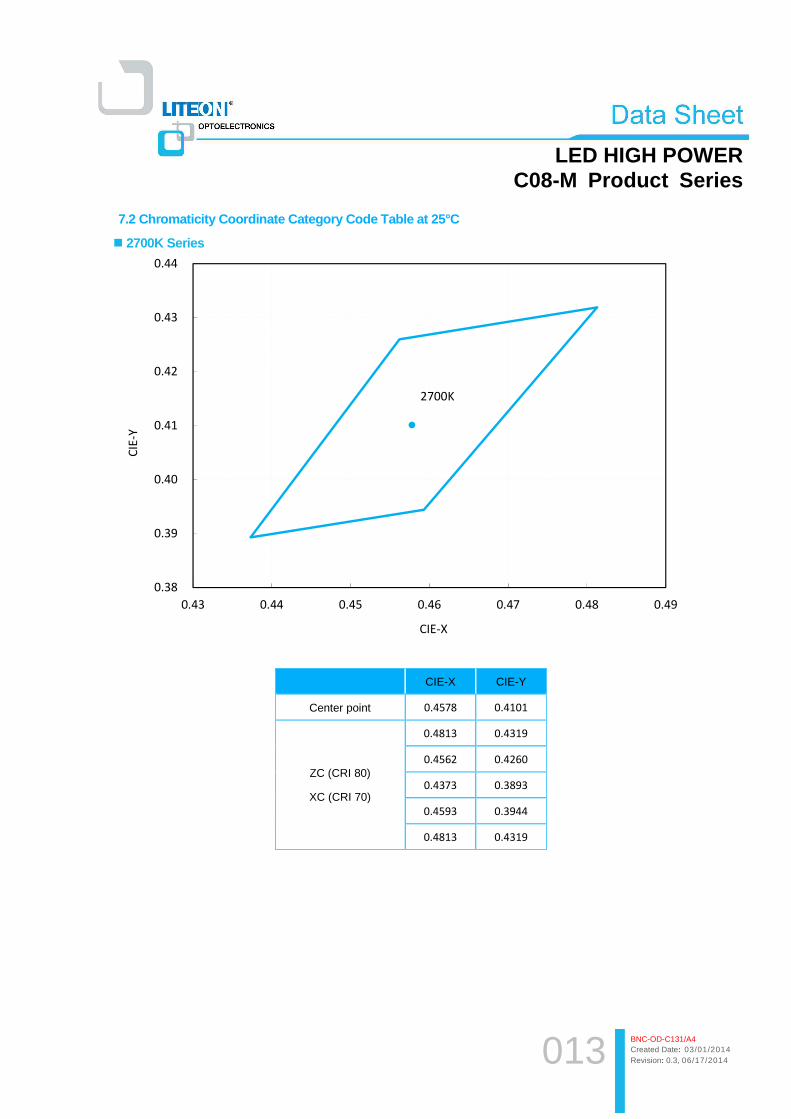
7.2 Chromaticity Coordinate Category Code Table at 25°C
� 2700K Series
2700K
0.38
0.39
0.40
0.41
0.42
0.43
0.44
0.43 0.44 0.45 0.46 0.47 0.48 0.49
CIE
-Y
CIE-X
CIE-X CIE-Y
Center point 0.4578 0.4101
ZC (CRI 80)
XC (CRI 70)
0.4813 0.4319
0.4562 0.4260
0.4373 0.3893
0.4593 0.3944
0.4813 0.4319
014
LED HIGH POWER C08-M Product Series
BNC-OD-C131/A4 Created Date: 03/01/2014 Revision: 0.3, 06/17/2014
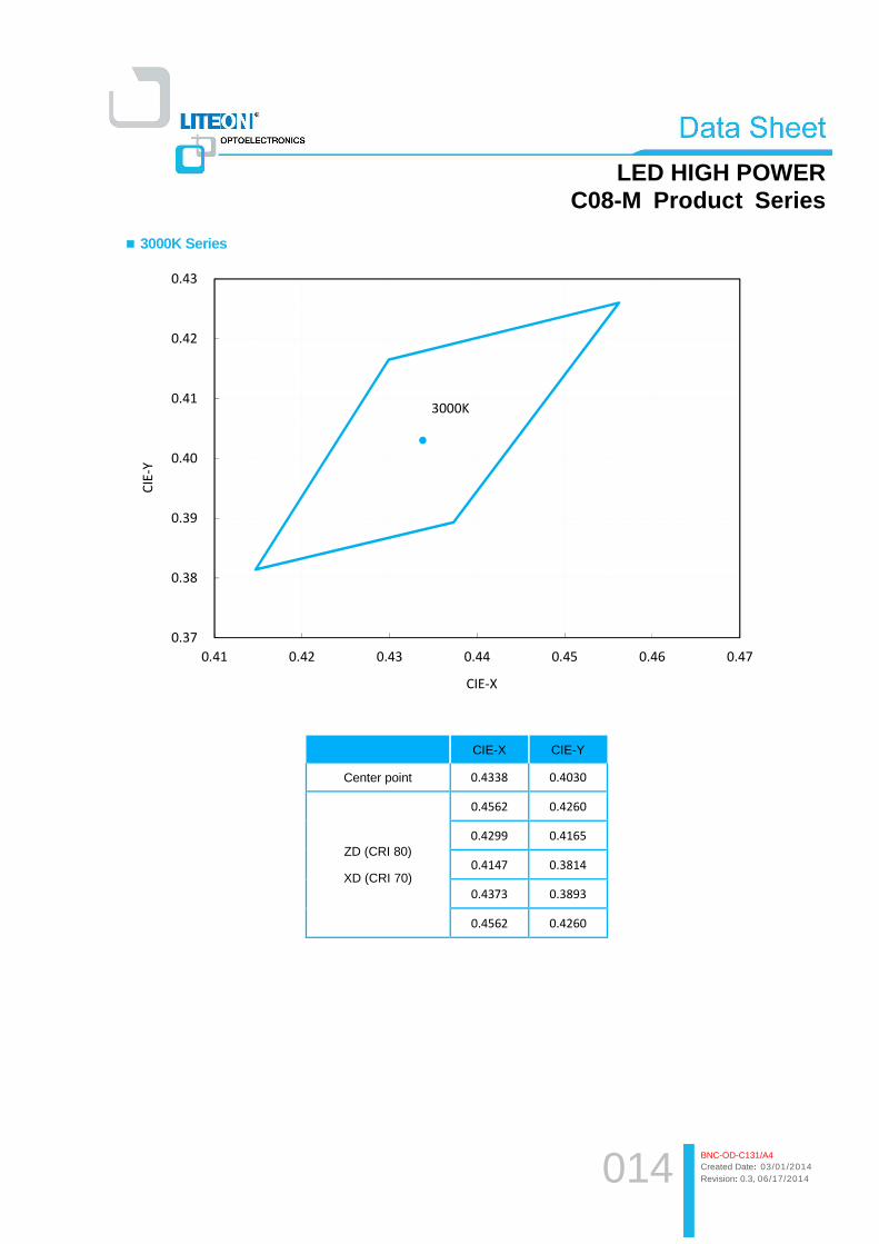
� 3000K Series
3000K
0.37
0.38
0.39
0.40
0.41
0.42
0.43
0.41 0.42 0.43 0.44 0.45 0.46 0.47
CIE
-Y
CIE-X
CIE-X CIE-Y
Center point 0.4338 0.4030
ZD (CRI 80)
XD (CRI 70)
0.4562 0.4260
0.4299 0.4165
0.4147 0.3814
0.4373 0.3893
0.4562 0.4260
015
LED HIGH POWER C08-M Product Series
BNC-OD-C131/A4 Created Date: 03/01/2014 Revision: 0.3, 06/17/2014
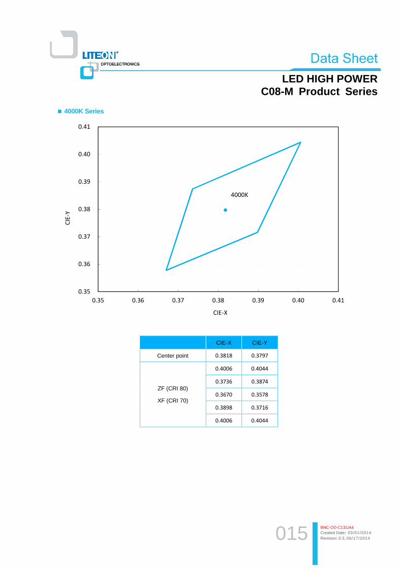
� 4000K Series
4000K
0.35
0.36
0.37
0.38
0.39
0.40
0.41
0.35 0.36 0.37 0.38 0.39 0.40 0.41
CIE
-Y
CIE-X
CIE-X CIE-Y
Center point 0.3818 0.3797
ZF (CRI 80)
XF (CRI 70)
0.4006 0.4044
0.3736 0.3874
0.3670 0.3578
0.3898 0.3716
0.4006 0.4044

016
LED HIGH POWER C08-M Product Series
BNC-OD-C131/A4 Created Date: 03/01/2014 Revision: 0.3, 06/17/2014
� 5000K Series
5000K
0.32
0.33
0.34
0.35
0.36
0.37
0.38
0.32 0.33 0.34 0.35 0.36 0.37 0.38
CIE
-Y
CIE-X
CIE-X CIE-Y
Center point 0.3447 0.3553
ZH (CRI 80)
XH (CRI 70)
0.3551 0.3760
0.3376 0.3616
0.3366 0.3369
0.3515 0.3487
0.3551 0.3760
017
LED HIGH POWER C08-M Product Series
BNC-OD-C131/A4 Created Date: 03/01/2014 Revision: 0.3, 06/17/2014
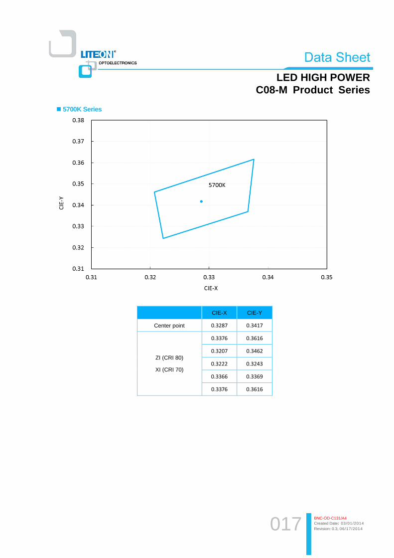
� 5700K Series
CIE-X CIE-Y
Center point 0.3287 0.3417
ZI (CRI 80)
XI (CRI 70)
0.3376 0.3616
0.3207 0.3462
0.3222 0.3243
0.3366 0.3369
0.3376 0.3616
018
LED HIGH POWER C08-M Product Series
BNC-OD-C131/A4 Created Date: 03/01/2014 Revision: 0.3, 06/17/2014
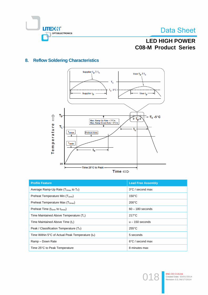
8. Reflow Soldering Characteristics
Profile Feature Lead Free Assembly
Average Ramp-Up Rate (TSmax to TP) 3°C / second max
Preheat Temperature Min (TSmin) 150°C
Preheat Temperature Max (TSmax) 200°C
Preheat Time (tSmin to tSmax) 60 – 180 seconds
Time Maintained Above Temperature (TL) 217°C
Time Maintained Above Time (tL) u – 150 seconds
Peak / Classification Temperature (TP) 255°C
Time Within 5°C of Actual Peak Temperature (tP) 5 seconds
Ramp – Down Rate 6°C / second max
Time 25°C to Peak Temperature 8 minutes max

019
LED HIGH POWER C08-M Product Series
BNC-OD-C131/A4 Created Date: 03/01/2014 Revision: 0.3, 06/17/2014
Notes:
1. The LEDs can be soldered using the reflow soldering or hand soldering method. The recommended hand soldering
condition is 350°C max. and 2secs max. for one time only, and the recommended reflow soldering condition is
260°C max. and 5secs max. for three times max.
2. All temperatures refer to topside of the package, measured on the package body surface.
3. The soldering condition referring to J-STD-020B. The storage ambient for the LEDs should not exceed 30°C
temperature or 70% relative humidity. It is recommended that LEDs out of their original packaging are soldered
within one week. For extended storage out of their original packaging, it is recommended that the LEDs were
stored in a sealed container with appropriate desiccant, or desiccators with nitrogen ambient. If the LEDs were
unpacked more than 168hrs, baking the LEDs at 60°C for 24hrs before soldering process.
4. The soldering profile could be further referred to different soldering grease material characteristic. The grease
vendor will provide this information.
5. A rapid-rate process is not recommended for the LEDs cooling down from the peak temperature.
6. Although the recommended reflow conditions are specified above, the reflow or hand soldering condition at
the lowest possible temperature is desirable for the LEDs.
7. LiteOn cannot make a guarantee on the LEDs which have been already assembled using the dip soldering
method.
020
LED HIGH POWER C08-M Product Series
BNC-OD-C131/A4 Created Date: 03/01/2014 Revision: 0.3, 06/17/2014
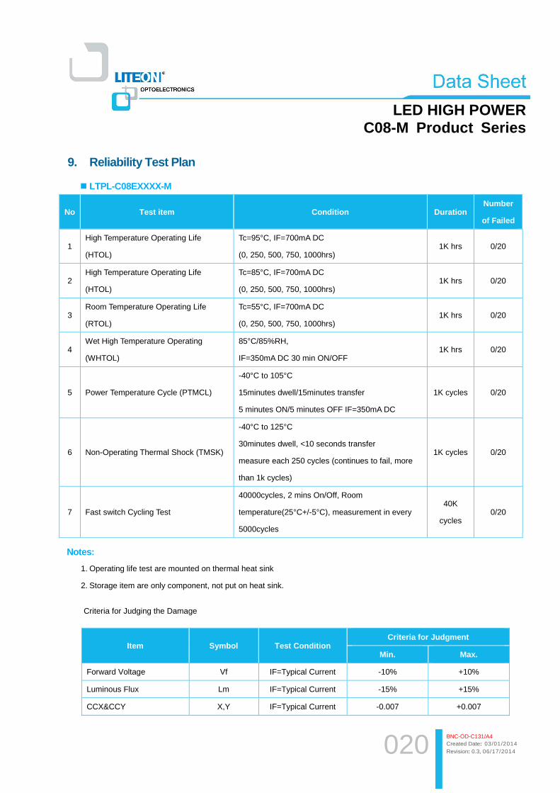
9. Reliability Test Plan
� LTPL-C08EXXXX-M
No Test item Condition Duration Number
of Failed
1 High Temperature Operating Life
(HTOL)
Tc=95°C, IF=700mA DC
(0, 250, 500, 750, 1000hrs) 1K hrs 0/20
2 High Temperature Operating Life
(HTOL)
Tc=85°C, IF=700mA DC
(0, 250, 500, 750, 1000hrs) 1K hrs 0/20
3 Room Temperature Operating Life
(RTOL)
Tc=55°C, IF=700mA DC
(0, 250, 500, 750, 1000hrs) 1K hrs 0/20
4 Wet High Temperature Operating
(WHTOL)
85°C/85%RH,
IF=350mA DC 30 min ON/OFF 1K hrs 0/20
5 Power Temperature Cycle (PTMCL)
-40°C to 105°C
15minutes dwell/15minutes transfer
5 minutes ON/5 minutes OFF IF=350mA DC
1K cycles 0/20
6 Non-Operating Thermal Shock (TMSK)
-40°C to 125°C
30minutes dwell, <10 seconds transfer
measure each 250 cycles (continues to fail, more
than 1k cycles)
1K cycles 0/20
7 Fast switch Cycling Test
40000cycles, 2 mins On/Off, Room
temperature(25°C+/-5°C), measurement in every
5000cycles
40K
cycles 0/20
Notes:
1. Operating life test are mounted on thermal heat sink
2. Storage item are only component, not put on heat sink.
Criteria for Judging the Damage
Item Symbol Test Condition Criteria for Judgment
Min. Max.
Forward Voltage Vf IF=Typical Current -10% +10%
Luminous Flux Lm IF=Typical Current -15% +15%
CCX&CCY X,Y IF=Typical Current -0.007 +0.007

021
LED HIGH POWER C08-M Product Series
BNC-OD-C131/A4 Created Date: 03/01/2014 Revision: 0.3, 06/17/2014
10. Recommend Soldering Pad Layout
Notes:
1. Suggest stencil thickness is maximum 0.10mm
022
LED HIGH POWER C08-M Product Series
BNC-OD-C131/A4 Created Date: 03/01/2014 Revision: 0.3, 06/17/2014
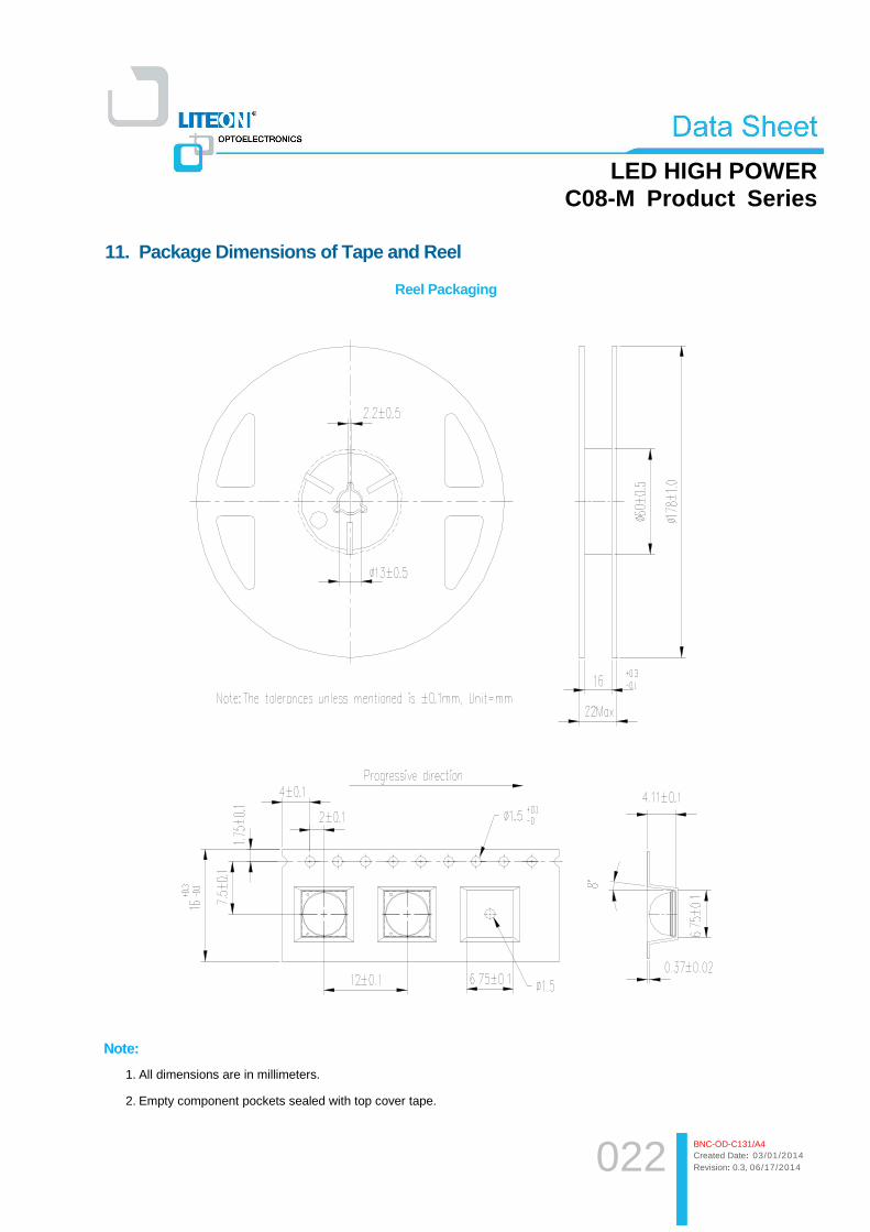
11. Package Dimensions of Tape and Reel
Reel Packaging
Note:
1. All dimensions are in millimeters.
2. Empty component pockets sealed with top cover tape.

023
LED HIGH POWER C08-M Product Series
BNC-OD-C131/A4 Created Date: 03/01/2014 Revision: 0.3, 06/17/2014
12. Cautions
12.1 An LED is a current-operated device. In order to ensure intensity uniformity on multiple LEDs connected in
parallel in an application, it is recommended that a current limiting resistor be incorporated in the drive circuit, in
series with each LED as shown in Circuit below.
LED
LED
Circuit model A Circuit model B
(A) Recommended circuit.
(B) The brightness of each LED might appear different due to the differences in the I-V characteristics of those
LEDs.
12.2 Do not put any pressure on the light emitting surface either by finger or any hand tool and do not stack the
COB products. Stress or pressure may cause damage to the wires of the LED array.
12.3 This product is not designed for the use under any of the following conditions, please confirm the performance
and reliability are well enough if you use it under any of the following conditions
・Do not use sulfur-containing materials in commercial products including the materials such as seals and
adhesives that may contain sulfur.
・Do not put this product in a place with a lot of moisture (over 85% relative humidity), dew condensation, briny air,
and corrosive gas (Cl, H2S, NH3, SO2, NOX, etc.), exposure to a corrosive environment may affect silver plating.
ESD (Electrostatic Discharge)
Static Electricity or power surge will damage the LED. Suggestions to prevent ESD damage:
Use of a conductive wrist band or anti-electrostatic glove when handling these LEDs.
All devices, equipment, and machinery must be properly grounded.
Work tables, storage racks, etc. should be properly grounded.
Use ion blower to neutralize the static charge which might have built up on surface of the LED’s plastic lens
as a result of friction between LEDs during storage and handling.
ESD-damaged LEDs will exhibit abnormal characteristics such as high reverse leakage current, low forward voltage,
or “no light up” at low currents.
To verify for ESD damage, check for “light up” and VF of the suspect LEDs at low currents.

024
LED HIGH POWER C08-M Product Series
BNC-OD-C131/A4 Created Date: 03/01/2014 Revision: 0.3, 06/17/2014
� Lens Handling Remark
The LED should only be picked up by making contact with the sides of the LED body. It should not put any pressure
on the lens either by finger or any hand tool. Do not puncture or push the lens. Below figure illustrate correct and
incorrect handling.
� Storage
The storage ambient for the LEDs should not exceed 30°C temperature or 85% relative humidity.