LED Driver Linear dimming Driver LCA 100W 350–1050mA 2xDT8 ...
15
www.tridonic.com 1 Subject to change without notice. Information provided without guarantee. Data sheet 12/21-LC482-16 LED driver Linear dimming Product description • Dimmable built-in constant current 4-channel LED driver with 2 x DALI-2 DT8 • Dimming range 3 – 100 % • Suitable for luminaires of protection class I and protection class II • Adjustable output current between 350 and 1,050 mA for each channel • Max. output power 100 W • Up to 90 % efficiency • Power input on stand-by < 0.25 W • Nominal lifetime up to 100,000 h • 5 years guarantee (conditions at www.tridonic.com) Housing properties • Low profile metal casing with white cover • Type of protection IP20 Interfaces • one4all (DALI-2 DT8, DSI, switchDIM, corridorFUNCTION V2) • colourSWITCH • Terminal blocks: 0° push terminals Functions • Adjustable output current in 1-mA-steps (DALI) or with resistor plug (I-SELECT 2) • Constant light output function (CLO) • colourSWITCH with predefined colours • switchDIM and colourSWITCH with memory function • Power-up fading and fade to zero • Configurable via DALI • Protective features (overtemperature, short-circuit, overload, no-load, reduced surge amplification) • Intelligent Voltage Guard (overvoltage and undervoltage monitoring) • Suitable for emergency lighting acc. to EN 50172 Benefits • Flexible configuration via companionSUITE • Application-oriented operating window for max. compatibility • Best energy savings due to low stand-by losses • Flexible configuration via DALI and I-SELECT 2 Typical applications • For linear/area lighting in office applications • Tunable white application È Standards, page 5 Driver LCA 100W 350–1050mA 2xDT8 lp PRE Tunable White DT8 premium SELV series
Transcript of LED Driver Linear dimming Driver LCA 100W 350–1050mA 2xDT8 ...
www.tridonic.com 1Subject to change without notice. Information provided without guarantee.
Data sheet 12/21-LC482-16
LED driver
Linear dimming
Product description
• Dimmable built-in constant current 4-channel LED driver with
2 x DALI-2 DT8
• Dimming range 3 – 100 %
• Suitable for luminaires of protection class I and protection class II
• Adjustable output current between 350 and 1,050 mA for each
channel
• Max. output power 100 W
• Up to 90 % efficiency
• Power input on stand-by < 0.25 W
• Nominal lifetime up to 100,000 h
• 5 years guarantee (conditions at www.tridonic.com)
Housing properties
• Low profile metal casing with white cover
• Type of protection IP20
Interfaces
• one4all (DALI-2 DT8, DSI, switchDIM, corridorFUNCTION V2)
• colourSWITCH
• Terminal blocks: 0° push terminals
Functions
• Adjustable output current in 1-mA-steps (DALI) or
with resistor plug (I-SELECT 2)
• Constant light output function (CLO)
• colourSWITCH with predefined colours
• switchDIM and colourSWITCH with memory function
• Power-up fading and fade to zero
• Configurable via DALI
• Protective features (overtemperature, short-circuit, overload,
no-load, reduced surge amplification)
• Intelligent Voltage Guard (overvoltage and undervoltage
monitoring)
• Suitable for emergency lighting acc. to EN 50172
Benefits
• Flexible configuration via companionSUITE
• Application-oriented operating window for max. compatibility
• Best energy savings due to low stand-by losses
• Flexible configuration via DALI and I-SELECT 2
Typical applications
• For linear/area lighting in office applications
• Tunable white application
ÈStandards, page 5
Driver LCA 100W 350–1050mA 2xDT8 lp PRE
Tunable White DT8 premium SELV series
www.tridonic.com 2Subject to change without notice. Information provided without guarantee.
Data sheet 12/21-LC482-16
LED driver
Linear dimming
EL
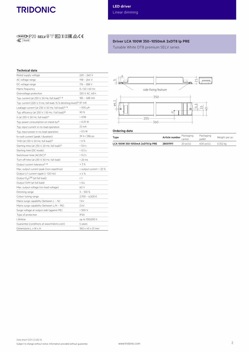
Technical dataRated supply voltage 220 – 240 V
AC voltage range 198 – 264 V
DC voltage range 176 – 288 V
Mains frequency 0 / 50 / 60 Hz
Overvoltage protection 320 V AC, 48 h
Typ. current (at 230 V, 50 Hz, full load)1 2 185 – 488 mA
Typ. current (220 V, 0 Hz, full load, 15 % dimming level)2 87 mA
Leakage current (at 230 V, 50 Hz, full load)1 2 < 500 µA
Typ. efficiency (at 230 V / 50 Hz / full load)2 90 %
λ (at 230 V, 50 Hz, full load)1 > 0.98
Typ. power consumption on stand-by3 < 0.25 W
Typ. input current in no-load operation 22 mA
Typ. input power in no-load operation < 0.5 W
In-rush current (peak / duration) 39 A / 286 µs
THD (at 230 V, 50 Hz, full load)1 < 6 %
Starting time (at 230 V, 50 Hz, full load)1 < 0.6 s
Starting time (DC mode) < 0.3 s
Switchover time (AC/DC)7 < 0.2 s
Turn off time (at 230 V, 50 Hz, full load) < 20 ms
Output current tolerance1 6 ± 3 %
Max. output current peak (non-repetitive) ≤ output current + 20 %
Output LF current ripple (< 120 Hz) ± 4 %
Output PstLM (at full load) ≤ 1
Output SVM (at full load) ≤ 0.4
Max. output voltage (no-load voltage) 60 V
Dimming range 3 – 100 %
Colour tuning range 2,700 – 6,500 K
Mains surge capability (between L – N) 1 kV
Mains surge capability (between L/N – PE) 2 kV
Surge voltage at output side (against PE) < 500 V
Type of protection IP20
Lifetime up to 100,000 h
Guarantee (conditions at www.tridonic.com) 5 years
Dimensions L x W x H 360 x 40 x 21 mm
Driver LCA 100W 350–1050mA 2xDT8 lp PRE
Tunable White DT8 premium SELV series
15
205
tc
360
4,1
40
350
ø4,1
6
5 21
side fixing feature
Ordering data
Type Article numberPackaging carton
Packaging pallet
Weight per pc.
LCA 100W 350-1050mA 2xDT8 lp PRE 28001911 20 pc(s). 600 pc(s). 0.352 kg
www.tridonic.com 3Subject to change without notice. Information provided without guarantee.
Data sheet 12/21-LC482-16
LED driver
Linear dimming
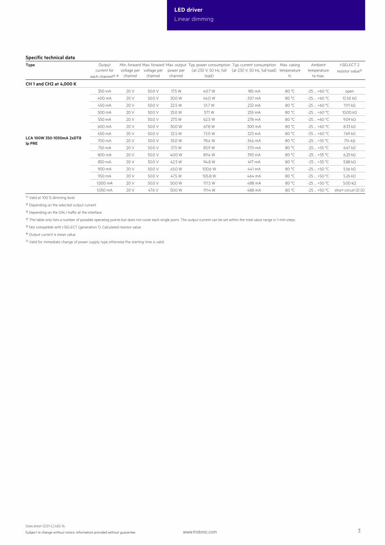
Specific technical dataType Output
current for
each channel4 6
Min. forward voltage per
channel
Max. forward voltage per
channel
Max. output power per channel
Typ. power consumption (at 230 V, 50 Hz, full
load)
Typ. current consumption (at 230 V, 50 Hz, full load)
Max. casing temperature
tc
Ambient temperature
ta max.
I-SELECT 2
resistor value4
CH 1 and CH2 at 4,000 K
LCA 100W 350-1050mA 2xDT8 lp PRE
350 mA 20 V 50.0 V 17.5 W 40.7 W 185 mA 80 °C -25 ... +60 °C open
400 mA 20 V 50.0 V 20.0 W 46.0 W 207 mA 80 °C -25 ... +60 °C 12.50 kΩ
450 mA 20 V 50.0 V 22.5 W 51.7 W 232 mA 80 °C -25 ... +60 °C 11.11 kΩ
500 mA 20 V 50.0 V 25.0 W 57.1 W 255 mA 80 °C -25 ... +60 °C 10.00 kΩ
550 mA 20 V 50.0 V 27.5 W 62.5 W 278 mA 80 °C -25 ... +60 °C 9.09 kΩ
600 mA 20 V 50.0 V 30.0 W 67.8 W 300 mA 80 °C -25 ... +60 °C 8.33 kΩ
650 mA 20 V 50.0 V 32.5 W 73.0 W 323 mA 80 °C -25 ... +60 °C 7.69 kΩ
700 mA 20 V 50.0 V 35.0 W 78.4 W 346 mA 80 °C -25 ... +55 °C 7.14 kΩ
750 mA 20 V 50.0 V 37.5 W 83.9 W 370 mA 80 °C -25 ... +55 °C 6.67 kΩ
800 mA 20 V 50.0 V 40.0 W 89.4 W 393 mA 80 °C -25 ... +55 °C 6.25 kΩ
850 mA 20 V 50.0 V 42.5 W 94.8 W 417 mA 80 °C -25 ... +55 °C 5.88 kΩ
900 mA 20 V 50.0 V 45.0 W 100.6 W 441 mA 80 °C -25 ... +50 °C 5.56 kΩ
950 mA 20 V 50.0 V 47.5 W 105.8 W 464 mA 80 °C -25 ... +50 °C 5.26 kΩ
1,000 mA 20 V 50.0 V 50.0 W 111.5 W 488 mA 80 °C -25 ... +50 °C 5.00 kΩ
1,050 mA 20 V 47.6 V 50.0 W 111.4 W 488 mA 80 °C -25 ... +50 °C short circuit (0 Ω)
1 Valid at 100 % dimming level.
2 Depending on the selected output current.
3 Depending on the DALI traffic at the interface.
4 The table only lists a number of possible operating points but does not cover each single point. The output current can be set within the total value range in 1-mA-steps.
5 Not compatible with I-SELECT (generation 1). Calculated resistor value.
6 Output current is mean value.
7 Valid for immediate change of power supply type otherwise the starting time is valid.
www.tridonic.com 4Subject to change without notice. Information provided without guarantee.
Data sheet 12/21-LC482-16
LED driver
Linear dimming
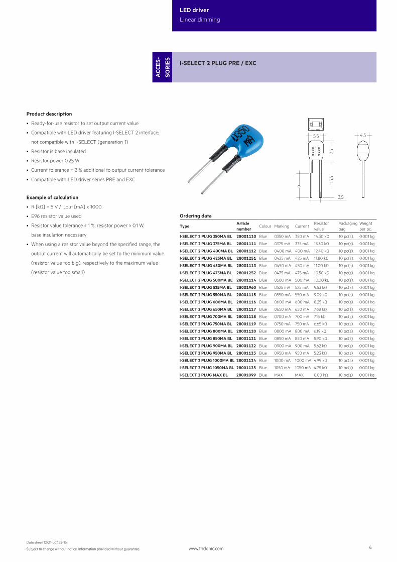
I-SELECT 2 PLUG PRE / EXC
ACC
ES-
SOR
IES
3,5
xxxx
xxxx
5,5 4,5
7,513,5
9
Ordering data
TypeArticle number
Colour Marking CurrentResistor value
Packaging bag
Weight per pc.
I-SELECT 2 PLUG 350MA BL 28001110 Blue 0350 mA 350 mA 14.30 kΩ 10 pc(s). 0.001 kg
I-SELECT 2 PLUG 375MA BL 28001111 Blue 0375 mA 375 mA 13.30 kΩ 10 pc(s). 0.001 kg
I-SELECT 2 PLUG 400MA BL 28001112 Blue 0400 mA 400 mA 12.40 kΩ 10 pc(s). 0.001 kg
I-SELECT 2 PLUG 425MA BL 28001251 Blue 0425 mA 425 mA 11.80 kΩ 10 pc(s). 0.001 kg
I-SELECT 2 PLUG 450MA BL 28001113 Blue 0450 mA 450 mA 11.00 kΩ 10 pc(s). 0.001 kg
I-SELECT 2 PLUG 475MA BL 28001252 Blue 0475 mA 475 mA 10.50 kΩ 10 pc(s). 0.001 kg
I-SELECT 2 PLUG 500MA BL 28001114 Blue 0500 mA 500 mA 10.00 kΩ 10 pc(s). 0.001 kg
I-SELECT 2 PLUG 525MA BL 28001960 Blue 0525 mA 525 mA 9.53 kΩ 10 pc(s). 0.001 kg
I-SELECT 2 PLUG 550MA BL 28001115 Blue 0550 mA 550 mA 9.09 kΩ 10 pc(s). 0.001 kg
I-SELECT 2 PLUG 600MA BL 28001116 Blue 0600 mA 600 mA 8.25 kΩ 10 pc(s). 0.001 kg
I-SELECT 2 PLUG 650MA BL 28001117 Blue 0650 mA 650 mA 7.68 kΩ 10 pc(s). 0.001 kg
I-SELECT 2 PLUG 700MA BL 28001118 Blue 0700 mA 700 mA 7.15 kΩ 10 pc(s). 0.001 kg
I-SELECT 2 PLUG 750MA BL 28001119 Blue 0750 mA 750 mA 6.65 kΩ 10 pc(s). 0.001 kg
I-SELECT 2 PLUG 800MA BL 28001120 Blue 0800 mA 800 mA 6.19 kΩ 10 pc(s). 0.001 kg
I-SELECT 2 PLUG 850MA BL 28001121 Blue 0850 mA 850 mA 5.90 kΩ 10 pc(s). 0.001 kg
I-SELECT 2 PLUG 900MA BL 28001122 Blue 0900 mA 900 mA 5.62 kΩ 10 pc(s). 0.001 kg
I-SELECT 2 PLUG 950MA BL 28001123 Blue 0950 mA 950 mA 5.23 kΩ 10 pc(s). 0.001 kg
I-SELECT 2 PLUG 1000MA BL 28001124 Blue 1000 mA 1000 mA 4.99 kΩ 10 pc(s). 0.001 kg
I-SELECT 2 PLUG 1050MA BL 28001125 Blue 1050 mA 1050 mA 4.75 kΩ 10 pc(s). 0.001 kg
I-SELECT 2 PLUG MAX BL 28001099 Blue MAX MAX 0.00 kΩ 10 pc(s). 0.001 kg
Product description
• Ready-for-use resistor to set output current value
• Compatible with LED driver featuring I-SELECT 2 interface;
not compatible with I-SELECT (generation 1)
• Resistor is base insulated
• Resistor power 0.25 W
• Current tolerance ± 2 % additional to output current tolerance
• Compatible with LED driver series PRE and EXC
Example of calculation
• R [kΩ] = 5 V / I_out [mA] x 1000
• E96 resistor value used
• Resistor value tolerance ≤ 1 %; resistor power ≥ 0.1 W;
base insulation necessary
• When using a resistor value beyond the specified range, the
output current will automatically be set to the minimum value
(resistor value too big), respectively to the maximum value
(resistor value too small)
www.tridonic.com 5Subject to change without notice. Information provided without guarantee.
Data sheet 12/21-LC482-16
LED driver
Linear dimming
1. Standards
EN 55015EN 61000-3-2EN 61000-3-3EN 61347-1 EN 61347-2-13 EN 62384EN 61547EN 62386-101 (DALI-2)EN 62386-102 (DALI-2)EN 62386-207According to EN 50172 for use in central battery systemsAccording to EN 60598-2-22 suitable for emergency lighting installations
2. Thermal details and lifetime
2.1 Expected lifetime
The LED driver is designed for a lifetime stated above under reference conditions and with a failure probability of less than 10 %.
The relation of tc to ta temperature depends also on the luminaire design. If the measured tc temperature is approx. 5 K below tc max., ta temperature should be checked and eventually critical components (e.g. ELCAP) measured. Detailed information on request.
Expected lifetime
TypeOutput current
(CH1 = CH2 = 4,000 K)ta 30 °C 35 °C 40 °C 50 °C 55 °C
LCA 100W 350-1050mA 2xDT8 lp PRE
350 – 700 mAtc 50 °C 55 °C 65 °C 75 °C 80 °C
Lifetime > 100,000 h > 100,000 h 100,000 h 75,000 h 50,000 h
700 – 900 mAtc 55 °C 60 °C 70 °C 80 °C 85 °C
Lifetime > 100,000 h > 100,000 h 75,000 h 50,000 h 30,000 h
900 – 1,050 mAtc 60 °C 65 °C 70 °C 80 °C –
Lifetime > 100,000 h 90,000 h 65,000 h 40,000 h –
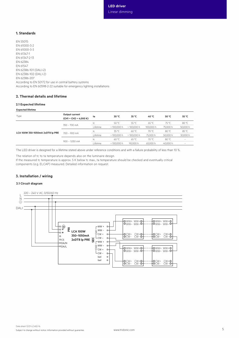
3. Installation / wiring
3.1 Circuit diagram
LN
DALI
220 – 240 V AC, 0/50/60 Hz
WW+
CW–
WW+
CW–
SEC
PRI WW +
WW –
CW +CW –WW +WW –
CW +CW –IselIsel
CSDA/NDA/L
~
WW– WW–
CW+CW+
WW+
CW–
WW+
CW–
WW– WW–
CW+CW+
WW+
CW–
WW+
CW–
WW– WW–
CW+CW+
WW+
CW–
WW+
CW–
WW– WW–
CW+CW+
~ CH1
CH2
LCA 100W350–1050mA2xDT8 lp PRE

www.tridonic.com 6Subject to change without notice. Information provided without guarantee.
Data sheet 12/21-LC482-16
LED driver
Linear dimming
LN
220 – 240 V AC, 0/50/60 Hz
WW+
CW–
WW+
CW–
LCA 100W350–1050mA2xDT8 lp PRE
PRI WW +
WW –
CW +CW –WW +WW –
CW +CW –IselIsel
CSDA/NDA/L
~
switchDIM
colourSWITCH
WW– WW–
CW+CW+
WW+
CW–
WW+
CW–
WW– WW–
CW+CW+
WW+
CW–
WW+
CW–
WW– WW–
CW+CW+
WW+
CW–
WW+
CW–
WW– WW–
CW+CW+
~
SEC
CH1
CH2
Neutral
++––+–
PO
Lout
Lin
N
L
EM ConverterLEDNeutral
Un-Switched LineTestswitchIndicatorLED
Switched Line out
Switched Line inControl gear
LEDLED
Control gearBatteryBattery
WW+
CW–
WW+
CW–
WW– WW–
CW+CW+
WW+
CW–
WW+
CW–
WW– WW–
CW+CW+
SEC
PRI WW +
WW –
CW +CW –WW +WW –
CW +CW –IselIsel
CSDA/NDA/L
~~ CH
1CH
2
LCA 100W350–1050mA2xDT8 lp PRE
Wiring diagram for emergency
www.tridonic.com 7Subject to change without notice. Information provided without guarantee.
Data sheet 12/21-LC482-16
LED driver
Linear dimming
LED module/LED driver/supply
8 – 9 mm
wire preparation:0.5 – 1.5 mm²
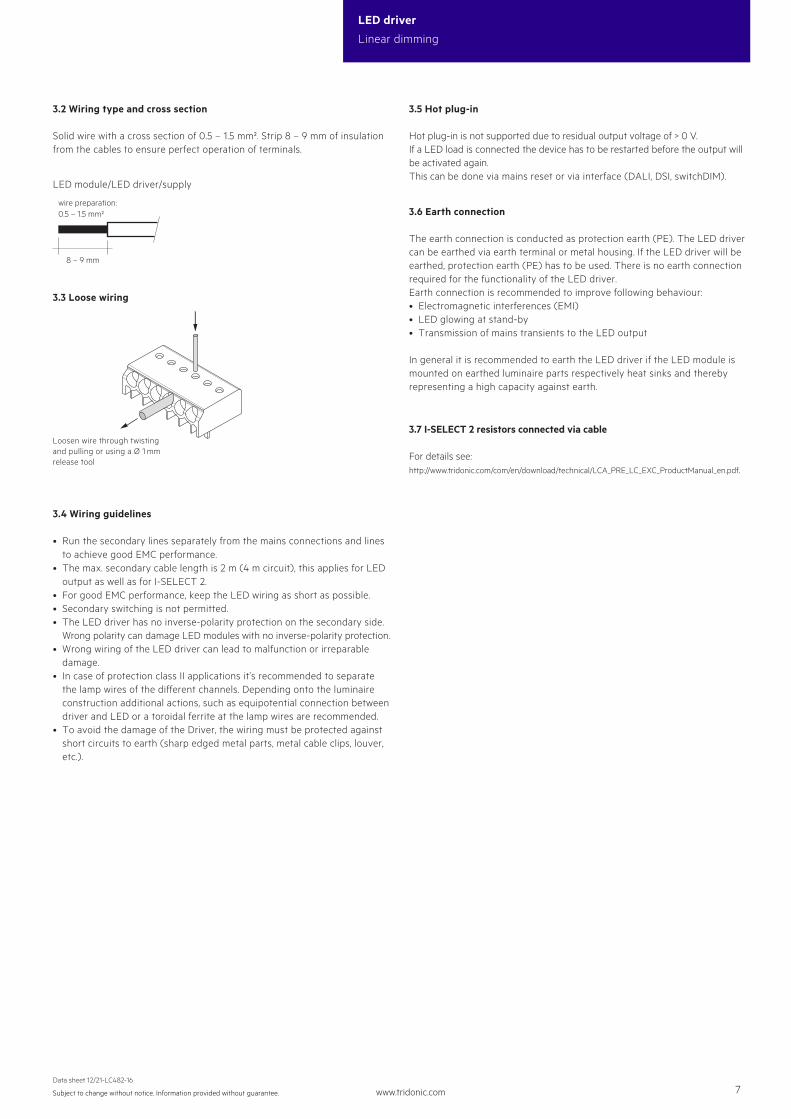
3.2 Wiring type and cross section
Solid wire with a cross section of 0.5 – 1.5 mm². Strip 8 – 9 mm of insulationfrom the cables to ensure perfect operation of terminals.
3.3 Loose wiring
Loosen wire through twisting and pulling or using a Ø 1 mm release tool
3.4 Wiring guidelines
• Run the secondary lines separately from the mains connections and lines to achieve good EMC performance.
• The max. secondary cable length is 2 m (4 m circuit), this applies for LED output as well as for I-SELECT 2.• For good EMC performance, keep the LED wiring as short as possible.• Secondary switching is not permitted.• The LED driver has no inverse-polarity protection on the secondary side. Wrong polarity can damage LED modules with no inverse-polarity protection.• Wrong wiring of the LED driver can lead to malfunction or irreparable damage.• In case of protection class II applications it’s recommended to separate the lamp wires of the different channels. Depending onto the luminaire construction additional actions, such as equipotential connection between driver and LED or a toroidal ferrite at the lamp wires are recommended.• To avoid the damage of the Driver, the wiring must be protected against short circuits to earth (sharp edged metal parts, metal cable clips, louver, etc.).
3.5 Hot plug-in
Hot plug-in is not supported due to residual output voltage of > 0 V. If a LED load is connected the device has to be restarted before the output will be activated again. This can be done via mains reset or via interface (DALI, DSI, switchDIM).
3.6 Earth connection
The earth connection is conducted as protection earth (PE). The LED driver can be earthed via earth terminal or metal housing. If the LED driver will be earthed, protection earth (PE) has to be used. There is no earth connection required for the functionality of the LED driver. Earth connection is recommended to improve following behaviour:• Electromagnetic interferences (EMI)• LED glowing at stand-by• Transmission of mains transients to the LED output
In general it is recommended to earth the LED driver if the LED module is mounted on earthed luminaire parts respectively heat sinks and thereby representing a high capacity against earth.
3.7 I-SELECT 2 resistors connected via cable
For details see: http://www.tridonic.com/com/en/download/technical/LCA_PRE_LC_EXC_ProductManual_en.pdf.
www.tridonic.com 8Subject to change without notice. Information provided without guarantee.
Data sheet 12/21-LC482-16
LED driver
Linear dimming
4. Electrical values
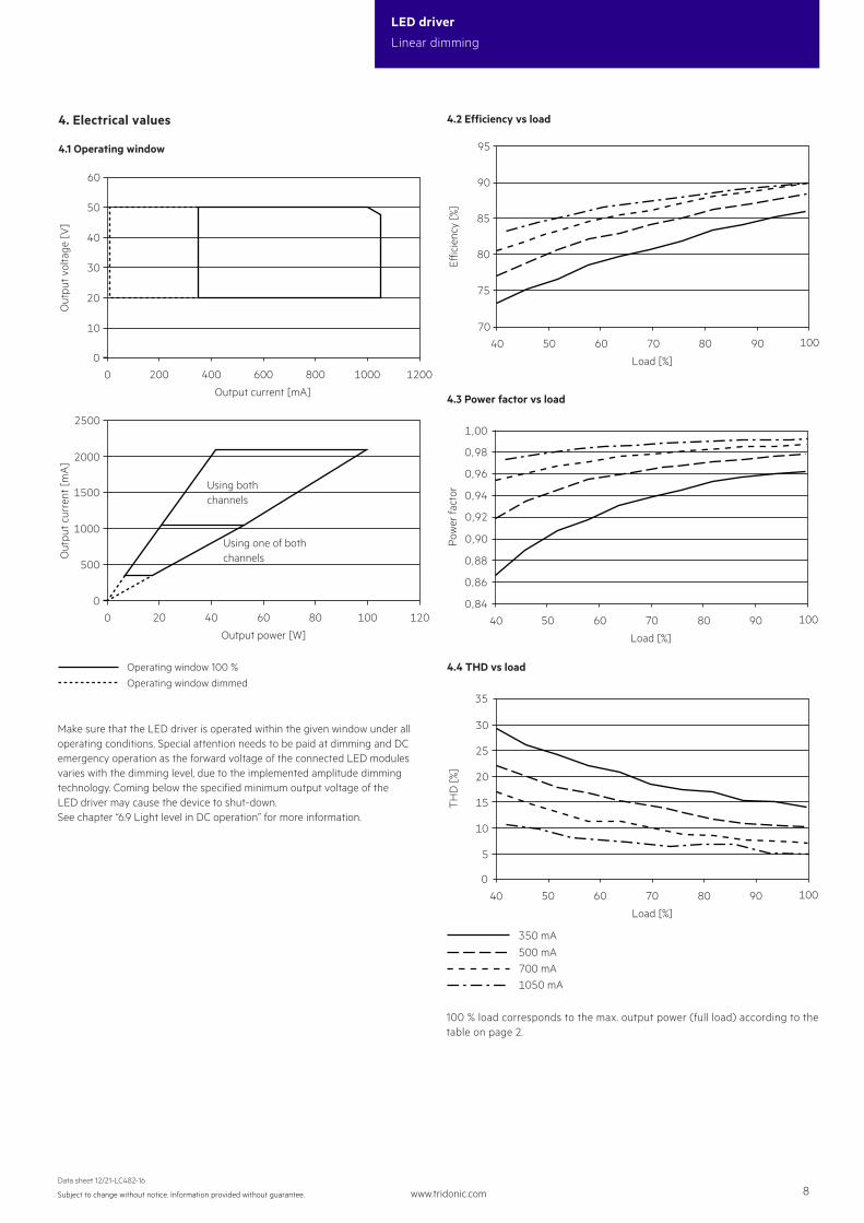
4.1 Operating window
Operating window 100 %Operating window dimmed
0
10
20
40
30
600 800 1000200 400 1200
60
50
0
Output current [mA]
Out
put v
olta
ge [V
]
0
500
1500
1000
60 80 10020 40 120
2500
2000
0
Using one of bothchannels
Using bothchannels
Output power [W]
Out
put c
urre
nt [m
A]
Make sure that the LED driver is operated within the given window under all operating conditions. Special attention needs to be paid at dimming and DC emergency operation as the forward voltage of the connected LED modules varies with the dimming level, due to the implemented amplitude dimming technology. Coming below the specified minimum output voltage of the LED driver may cause the device to shut-down. See chapter “6.9 Light level in DC operation” for more information.
70
80
85
75
90
40 60 70 80 9050 100
95
Load [%]
Eic
ienc
y [%
]
4.2 Efficiency vs load
0,84
0,86
0,88
0,92
0,90
0,94
0,96
0,98
1,00
40 60 70 80 9050 100
Load [%]
Pow
er fa
ctor
4.3 Power factor vs load
0
35
40 80 9060 7050 100
10
5
25
15
20
30
Load [%]
TH
D [%
]
4.4 THD vs load
100 % load corresponds to the max. output power (full load) according to the table on page 2.
350 mA
700 mA500 mA
1050 mA
www.tridonic.com 9Subject to change without notice. Information provided without guarantee.
Data sheet 12/21-LC482-16
LED driver
Linear dimming
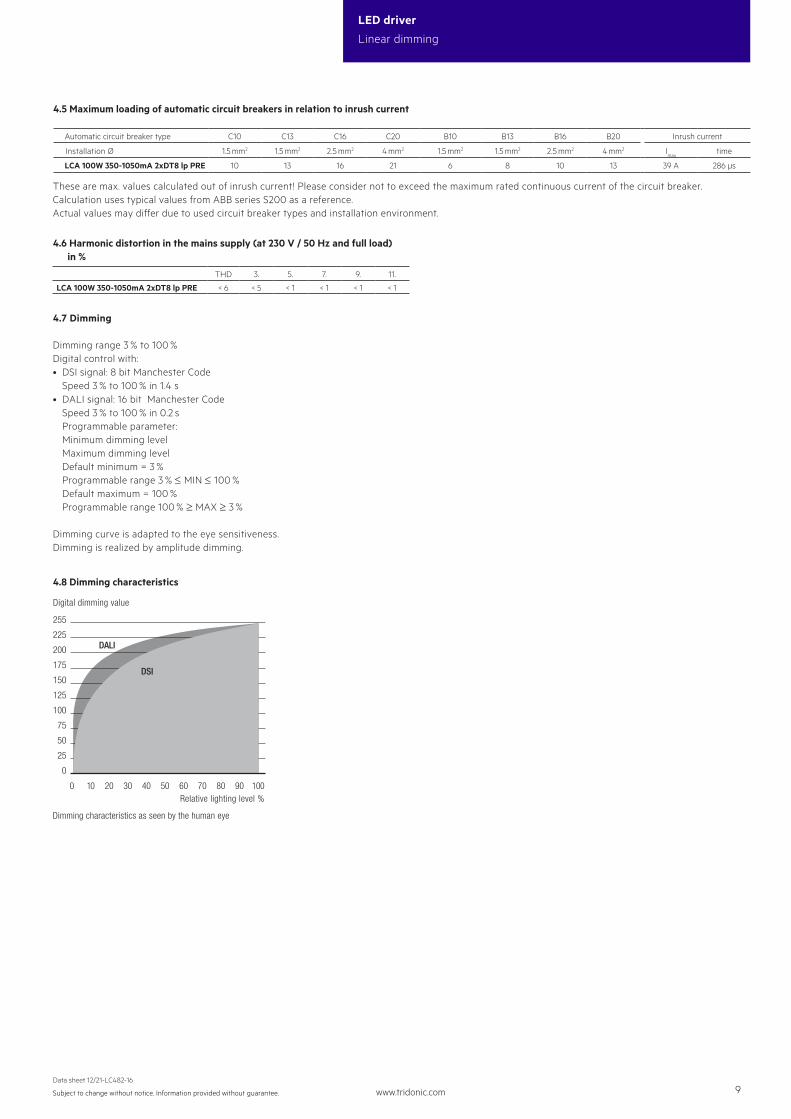
Automatic circuit breaker type C10 C13 C16 C20 B10 B13 B16 B20 Inrush current
Installation Ø 1.5 mm2 1.5 mm2 2.5 mm2 4 mm2 1.5 mm2 1.5 mm2 2.5 mm2 4 mm2 Imax
time
LCA 100W 350-1050mA 2xDT8 lp PRE 10 13 16 21 6 8 10 13 39 A 286 µs
225
255
DALI200
175
150
125
100
75
50
25
0
1009080706050403020100
Dimming characteristics
Digital dimming value
Relative lighting level %
DSI
Dimming characteristics as seen by the human eye
4.7 Dimming
Dimming range 3 % to 100 %Digital control with:• DSI signal: 8 bit Manchester Code
Speed 3 % to 100 % in 1.4 s• DALI signal: 16 bit Manchester Code Speed 3 % to 100 % in 0.2 s Programmable parameter:
Minimum dimming level Maximum dimming level
Default minimum = 3 % Programmable range 3 % ≤ MIN ≤ 100 % Default maximum = 100 % Programmable range 100 % ≥ MAX ≥ 3 %
Dimming curve is adapted to the eye sensitiveness.Dimming is realized by amplitude dimming.
4.8 Dimming characteristics
4.6 Harmonic distortion in the mains supply (at 230 V / 50 Hz and full load) in %
THD 3. 5. 7. 9. 11.
LCA 100W 350-1050mA 2xDT8 lp PRE < 6 < 5 < 1 < 1 < 1 < 1
4.5 Maximum loading of automatic circuit breakers in relation to inrush current
These are max. values calculated out of inrush current! Please consider not to exceed the maximum rated continuous current of the circuit breaker. Calculation uses typical values from ABB series S200 as a reference.Actual values may differ due to used circuit breaker types and installation environment.
www.tridonic.com 10Subject to change without notice. Information provided without guarantee.
Data sheet 12/21-LC482-16
LED driver
Linear dimming
5. Software / Programming / Interfaces
5.2 Control input DALI
The control input is non-polar for digital control signals (DALI). The control signal is not SELV. The control cable has to be installed in accordance to the requirements of low voltage installations.
Digital control with:• DALI signal: 16 bit• DSI signal: 8 bit
5.1 Software / programming
With appropriate software and interface different functions can be activated and various parameters can be configured in the LED driver.The Driver supports the following software and interfaces:
Software / hardware for configuration:• companionSUITE (deviceGENERATOR, deviceCONFIGURATOR,
deviceANALYSER)• masterCONFIGURATOR
Interfaces for data transfer:• Control input DALI
5.3 I-SELECT 2
By inserting a suitable resistor into the I-SELECT 2 interface, the current value can be adjusted. The relationship between output current and resistor value can be found in the chapter “Accessories I-SELECT 2 Plugs”. If the resistor is connected by wires a consistent base insulation must be ensured. Furthermore, a max. wire length of 2 m may not be exceeded and potential interferences have to be avoided.
Resistors for the main output current values can be ordered from Tridonic (see accessories).
www.tridonic.com 11Subject to change without notice. Information provided without guarantee.
Data sheet 12/21-LC482-16
LED driver
Linear dimming
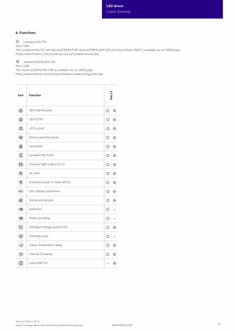
6. Functions
companionSUITE:DALI-USBThe companionSUITE with deviceGENERATOR, deviceCONFIGURATOR and deviceANALYSER is available via our WEB page:https://www.tridonic.com/com/en/products/companionsuite.asp
masterCONFIGURATOR:DALI-USBThe masterCONFIGURATOR is available via our WEB page:https://www.tridonic.com/com/en/software-masterconfigurator.asp
Icon Function
DA
LI-2
OEM Identification
OEM GTIN
LED current
Device operating mode
switchDIM
corridorFUNCTION
Constant light output (CLO)
DC level
Enhanced power on level (ePOL)
DALI default parameters
Scenes and groups
fade2zero –
Power-up fading –
Intelligent voltage guard (IVG)
Dimming curve –
Colour temperature range
Channel Grouping
colourSWITCH –
www.tridonic.com 12Subject to change without notice. Information provided without guarantee.
Data sheet 12/21-LC482-16
LED driver
Linear dimming
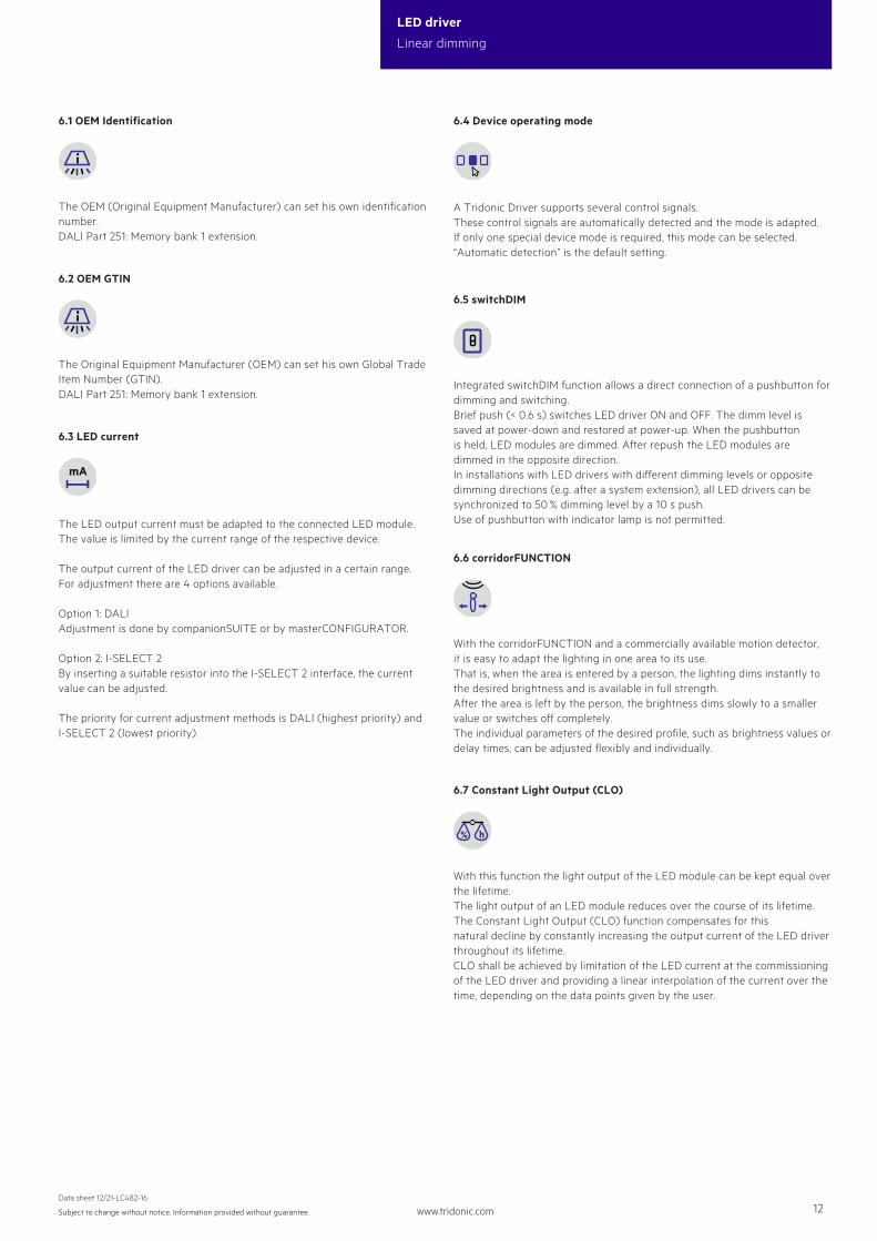
6.3 LED current
The LED output current must be adapted to the connected LED module.The value is limited by the current range of the respective device.
The output current of the LED driver can be adjusted in a certain range. For adjustment there are 4 options available.
Option 1: DALI Adjustment is done by companionSUITE or by masterCONFIGURATOR.
Option 2: I-SELECT 2 By inserting a suitable resistor into the I-SELECT 2 interface, the current value can be adjusted.
The priority for current adjustment methods is DALI (highest priority) and I-SELECT 2 (lowest priority).
6.1 OEM Identification
The OEM (Original Equipment Manufacturer) can set his own identification number.DALI Part 251: Memory bank 1 extension.
6.2 OEM GTIN
The Original Equipment Manufacturer (OEM) can set his own Global Trade Item Number (GTIN).DALI Part 251: Memory bank 1 extension.
6.4 Device operating mode
A Tridonic Driver supports several control signals. These control signals are automatically detected and the mode is adapted.If only one special device mode is required, this mode can be selected.“Automatic detection” is the default setting.
6.6 corridorFUNCTION
With the corridorFUNCTION and a commercially available motion detector, it is easy to adapt the lighting in one area to its use. That is, when the area is entered by a person, the lighting dims instantly to the desired brightness and is available in full strength. After the area is left by the person, the brightness dims slowly to a smaller value or switches off completely. The individual parameters of the desired profile, such as brightness values or delay times, can be adjusted flexibly and individually.
6.7 Constant Light Output (CLO)
With this function the light output of the LED module can be kept equal over the lifetime.The light output of an LED module reduces over the course of its lifetime.The Constant Light Output (CLO) function compensates for this natural decline by constantly increasing the output current of the LED driver throughout its lifetime.CLO shall be achieved by limitation of the LED current at the commissioning of the LED driver and providing a linear interpolation of the current over the time, depending on the data points given by the user.
6.5 switchDIM
Integrated switchDIM function allows a direct connection of a pushbutton for dimming and switching.Brief push (< 0.6 s) switches LED driver ON and OFF. The dimm level is saved at power-down and restored at power-up. When the pushbutton is held, LED modules are dimmed. After repush the LED modules are dimmed in the opposite direction.In installations with LED drivers with different dimming levels or opposite dimming directions (e.g. after a system extension), all LED drivers can be synchronized to 50 % dimming level by a 10 s push.Use of pushbutton with indicator lamp is not permitted.
www.tridonic.com 13Subject to change without notice. Information provided without guarantee.
Data sheet 12/21-LC482-16
LED driver
Linear dimming
The LED driver is designed to operate on DC voltage and pulsed DC voltage. For a reliable operation, make sure that also in DC emergency operation the LED driver is run within the specified conditions as stated in chapter “4.1 operating window”. Light output level in DC operation: programmable 1 – 100 % (factory default = 15 %, EOFi = 0.13).
The voltage-dependent input current of Driver incl. LED module is depending on the used load.
The voltage-dependent no-load current of Driver (without or defect LED module) is for:AC: < 21.8 mADC: 5 – 7 mA
In DC operation dimming mode can be activated.If Dimming on DC is activated the requirements of the DC recognition function are ignored.Even if DC is detected, the LED driver continues to behave as in AC mode
• The present dimming level is retained• An emergency light level defined for the DC recognition function (DC level) is ignored• Control signals via DALI continue to be executed
If Dimming on DC is activated then emergency mode is not recognised. The device no longer automatically switches to the emergency light level.
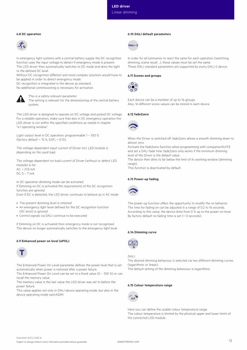
6.8 DC operation
In emergency light systems with a central battery supply the DC recognition function uses the input voltage to detect if emergency mode is present. The LED driver then automatically switches to DC mode and dims the light to the defined DC level.Without DC recognition different and more complex solutions would have to be applied in order to detect emergency mode.DC recognition is integrated in the device as standard. No additional commissioning is necessary for activation.
This is a safety-relevant parameter.The setting is relevant for the dimensioning of the central battery system.
6.9 Enhanced power on level (ePOL)
The Enhanced Power On Level parameter defines the power level that is set automatically when power is restored after a power failure.The Enhanced Power On Level can be set to a fixed value (0 – 100 %) or can recall the memory value.The memory value is the last value the LED driver was set to before the power failure.This value applies not only in DALI device operating mode, but also in the device operating mode switchDIM.
6.13 Power-up fading
The power-up function offers the opportunity to modify the on behavior. The time for fading on can be adjusted in a range of 0.2 to 16 seconds. According to this value, the device dims from 0 % up to the power-on level. By factory default no fading time is set (= 0 seconds).
6.10 DALI default parameters
In order for all luminaires to react the same for each operation (switching, dimming, scene recall ...), these values must be set the same.These DALI standard parameters are supported by every DALI-2 device.
6.11 Scenes and groups
Each device can be a member of up to 16 groups.Also, 16 different scene values can be stored in each device.
6.14 Dimming curve
DALI:The desired dimming behaviour is selected via two different dimming curves (logarithmic or linear).The default setting of the dimming behaviour is logarithmic.
6.15 Colour temperature range
Here you can define the usable colour temperature range.The colour temperature is limited by the physical upper and lower limits of the connected LED module.
6.12 fade2zero
When the Driver is switched off, fade2zero allows a smooth dimming down to almost zero.Activate the fade2zero function when programming with companionSUITE and set a DALI fade time. fade2zero only works if the minimum dimming level of the Driver is the default value.The device then dims to far below the limit of its working window (dimming range).This function is deactivated by default.
www.tridonic.com 14Subject to change without notice. Information provided without guarantee.
Data sheet 12/21-LC482-16
LED driver
Linear dimming
7. Protective features
7.2 Intelligent Voltage Guard (IVG)
The Intelligent Voltage Guard (IVG) function warns of possible damage due to overvoltage or undervoltage.The mains voltage is constantly monitored and if necessary appropriate responses are made:
• If the mains voltage is too low (< 70 V), the LED driver is switched off.• At a mains voltage between 70 and 140 V, the LED driver switches off and on again on a non-cyclic basis.• In case of an overvoltage (> 318 V), the LED driver sends feedback via DALI.
7.6 Insulation between terminals
Insulation Mains PE LED DALIMains – basic double basicPE basic – basic basicLED double basic – doubleDALI basic basic double –basic ... represents basic insulation.
double ... represents double or reinforced insulation.
7.3 Short-circuit behaviour
In case of a short-circuit at the LED output the LED output is switched off. After restart of the LED driver the output will be activated again. The restart can either be done via mains reset or via interface (DALI, DSI, switchDIM).
7.5 Overload protection
If the maximum load is exceeded by a defined internal limit, the LED driver turns off the LED output. After restart of the LED driver the output will be activated again. The restart can either be done via mains reset or via interface (DALI, DSI, switchDIM).
7.4 No-load operation
The LED driver will not be damaged in no-load operation. The output will be deactivated and is therefore free of voltage. If a LED load is connected the device has to be restarted before the output will be activated again.
7.1 Intelligent temperature guard (ITG)
The Intelligent temperature guard (ITG) function provides effective protec-tion against thermal overloads by slowly reducing the output if a defined internal temperature is exceeded.The reduction of overtemperatures takes place in small steps every two minutes. As soon as the temperature drops again, the output power is gradu-ally increased every 10 minutes. On DC operation this function is deactivated to fulfill emergency requirements.
6.16 Channel grouping
With this, the number of output channels can be split / grouped differently.This is important for the control of the device. The physical LED outputs are assigned to different logical units (DALI addresses).
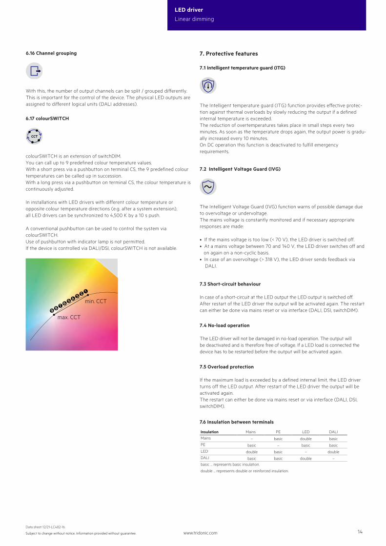
6.17 colourSWITCH
colourSWITCH is an extension of switchDIM.You can call up to 9 predefined colour temperature values.With a short press via a pushbutton on terminal CS, the 9 predefined colour temperatures can be called up in succession.With a long press via a pushbutton on terminal CS, the colour temperature is continuously adjusted.
In installations with LED drivers with different colour temperature or opposite colour temperature directions (e.g. after a system extension), all LED drivers can be synchronized to 4,500 K by a 10 s push.
A conventional pushbutton can be used to control the system via colourSWITCH. Use of pushbutton with indicator lamp is not permitted.If the device is controlled via DALI/DSI, colourSWITCH is not available.
min. CCT
max. CCT)(/&%$§"!
www.tridonic.com 15Subject to change without notice. Information provided without guarantee.
Data sheet 12/21-LC482-16
LED driver
Linear dimming
8.2 Conditions of use and storage
Humidity: 5 % up to max. 85 %, not condensed (max. 56 days/year at 85 %)
Storage temperature: -40 °C up to max. +80 °C
The devices have to be acclimatised to the specified temperature range (ta) before they can be operated.
The LED driver is declared as inbuilt LED controlgear, meaning it is intended to be used within a luminaire enclosure.If the product is used outside a luminaire, the installation must provide suitable protection for people and environment (e.g. in illuminated ceilings).
8.1 Insulation and electric strength testing of luminaires
Electronic devices can be damaged by high voltage. This has to be considered during the routine testing of the luminaires in production.
According to IEC 60598-1 Annex Q (informative only!) or ENEC 303-Annex A, each luminaire should be submitted to an insulation test with 500 V DC for 1 second. This test voltage should be connected between the interconnected phase and neutral terminals and the earth terminal. The insulation resistance must be at least 2 MΩ.
As an alternative, IEC 60598-1 Annex Q describes a test of the electrical strength with 1500 V AC (or 1.414 x 1500 V DC). To avoid damage to the electronic devices this test must not be conducted.
8. Miscellaneous
8.4 Additional information
Additional technical information at www.tridonic.com → Technical Data
Lifetime declarations are informative and represent no warranty claim.No warranty if device was opened.
8.3 Maximum number of switching cycles
All LED driver are tested with 50,000 switching cycles.The actually achieved number of switching cycles is significantly higher.