LED Driver Linear / area fixed output Driver LC 65W 250 ... · LC 65W 350mA fixC lp ADV 350 mA 83 V...
7
www.tridonic.com 1 Subject to change without notice. Data sheet 10/16-LC149-4 LED Driver Linear / area fixed output Product description • Fixed output constant current built-in LED Driver • Output current 250, 300 or 350 mA • Max. output power 65 W • Nominal life-time up to 50,000 h • For class I luminaires • Temperature protection as per EN 61347-2-13 C5e • 5-year guarantee Properties • Low-profile metal casing with white cover • Type of protection IP20 Functions • Intelligent Temperature Guard (overtemperature protection) • Short-circuit proof • Overload protection • Burst protection voltage 1 kV • Surge protection voltage 1 kV (L to N) • Surge protection voltage 2 kV (L/N to earth) È Standards, page 3 Driver LC 65W 250/300/350mA fixC lp ADV ADVANCED series
Transcript of LED Driver Linear / area fixed output Driver LC 65W 250 ... · LC 65W 350mA fixC lp ADV 350 mA 83 V...
www.tridonic.com 1Subject to change without notice.
Data sheet 10/16-LC149-4
LED Driver
Linear / area fixed output
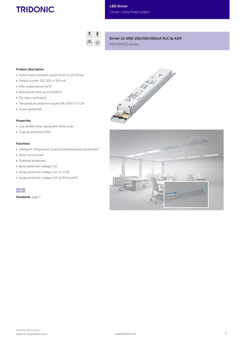
Product description
• Fixed output constant current built-in LED Driver
• Output current 250, 300 or 350 mA
• Max. output power 65 W
• Nominal life-time up to 50,000 h
• For class I luminaires
• Temperature protection as per EN 61347-2-13 C5e
• 5-year guarantee
Properties
• Low-profile metal casing with white cover
• Type of protection IP20
Functions
• Intelligent Temperature Guard (overtemperature protection)
• Short-circuit proof
• Overload protection
• Burst protection voltage 1 kV
• Surge protection voltage 1 kV (L to N)
• Surge protection voltage 2 kV (L/N to earth)
ÈStandards, page 3
Driver LC 65W 250/300/350mA fixC lp ADV
ADVANCED series

www.tridonic.com 2Subject to change without notice.
Data sheet 10/16-LC149-4
LED Driver
Linear / area fixed output
Specific technical dataType Output
current1Min. forward
voltage Max. forward
voltageMax. output
powerInput power (at 230 V,
50 Hz, full load)Input current (at 230 V, 50 Hz, full
load)
Efficiency (at 230 V, 50 Hz, full load)
Max. peak output current
tc point
LC 65W 250mA fixC lp ADV 250 mA 112 V 250 V 62.5 W 67.5 W 305 mA 93 % 337.5 mA 65 °C
LC 65W 300mA fixC lp ADV 300 mA 97 V 217 V 65.0 W 70.5 W 320 mA 92 % 405.0 mA 70 °C
LC 65W 350mA fixC lp ADV 350 mA 83 V 186 V 65.0 W 70.5 W 320 mA 92 % 472.5 mA 70 °C
1 Output current is mean value.
Technical dataRated supply voltage 220 – 240 V
AC voltage range 198 – 264 V
Mains frequency 50 / 60 Hz
Overvoltage protection 300 V AC, 1 h
λ (at 230 V, 50 Hz, full load) 0.98
Leakage current (PE) < 0.5 mA
THD (at 230 V, 50 Hz, full load) < 20 %
Output current tolerance1 ± 5 %
Typ. current ripple (at 230 V, 50 Hz, full load) < 3 %
Max. output voltage 250 V
Time to light < 0.5 s
Ambient temperature ta -20 ... +50 °C
Dimensions L x W x H 280 x 30 x 21 mm
Driver LC 65W 250/300/350mA fixC lp ADV
ADVANCED series
Ø4,1
4,1
30
215
6
280
270
side fixing feature
15
117
tc
LC 65W 250mA fixC lp ADV
tc
Ø4,1
4,1
30
215
6
280
270
side fixing feature
15
72
LC 65W 300mA fixC lp ADV + LC 65W 350mA fixC lp ADV
Ordering data
Type Article numberPackaging carton
Packaging, low volume
Packaging, high volume
Weight per pc.
LC 65W 250mA fixC lp ADV 87500456 50 pc(s). 900 pc(s). 2,700 pc(s). 0.186 kg
LC 65W 300mA fixC lp ADV 87500457 50 pc(s). 900 pc(s). 2,700 pc(s). 0.186 kg
LC 65W 350mA fixC lp ADV 87500458 50 pc(s). 900 pc(s). 2,700 pc(s). 0.185 kg

www.tridonic.com 3Subject to change without notice.
Data sheet 10/16-LC149-4
LED Driver
Linear / area fixed output
StandardsEN 55015EN 61000-3-2EN 61000-3-3EN 61347-2-13 EN 62384EN 61547
Humidity: 5 % up to max. 85 %, not condensed (max. 56 days/year at 85 %)
Storage temperature: -40 °C up to max. +80 °C
The devices have to be within the specified temperature range (ta) before they can be operated.
Overload protectionLED Driver will switch off at overload operation. Mains reset is required to restart the LED Driver.
Overtemperature protectionThe LED Driver will reduce output current at temporary thermal over-hea-ting (exceeding max. tc point).
Short-circuit behaviourLED Driver will switch off in case of short-circuit of LED output. Mains reset is required to restart the LED Driver.
No-load operation or load loss during operationLED Driver will detect a load loss during operation. In this case and no-load operation the max. output voltage can apply at the LED output for max. 5 s be-fore LED Driver shuts down. Mains reset is required to restart the LED Driver.
Temperature rangeThe LED Driver life duration is related to the ambient temperature ta.The relation of tc to ta temperature depends also on the luminaire design. If the measured tc temperature is approx. 5 K below tc max. or higher, ta tem-perature should be checked and eventually critical components (e.g. ELCAP) measured.Detailed information on request.
Expected life-timeType ta 40 °C 50 °C 60 °C
LC 65W 250mA fixC lp ADV tc 55 °C 65 °C x
life-time 50,000 h 30,000 h x
LC 65W 300mA fixC lp ADV tc 60 °C 70 °C x
life-time 50,000 h 30,000 h x
LC 65W 350mA fixC lp ADV tc 60 °C 70 °C x
life-time 50,000 h 30,000 h xx = not permitted
The LED Drivers are designed for a life-time stated above under reference conditions and with a failure probability of less than 10 %.
www.tridonic.com 4Subject to change without notice.
Data sheet 10/16-LC149-4
LED Driver
Linear / area fixed output
Isolation and electric strength testing of luminairesElectronic devices can be damaged by high voltage. This has to be considered during the routine testing of the luminaires in production.
According to IEC 60598-1 Annex Q (informative only!) or ENEC 303-Annex A, each luminaire should be submitted to an isolation test with 500 V DC for 1 second. This test voltage should be connected between the interconnected phase and neutral terminals and the earth terminal. The isolation resistance must be at least 2 MΩ.
As an alternative, IEC 60598-1 Annex Q describes a test of the electrical strength with 1500 V AC (or 1.414 x 1500 V DC). To avoid damage to the electronic devices this test must not be conducted.
Additional information
Additional technical information at www.tridonic.com → Technical Data
Guarantee conditions at www.tridonic.com → Services
No warranty if device was opened.
Maximum loading of automatic circuit breakers
Automatic circuit breaker type C10 C13 C16 C20 B10 B13 B16 B20 Inrush current
Installation Ø 1,5 mm2 1,5 mm2 2,5 mm2 2,5 mm2 1,5 mm2 1,5 mm2 2,5 mm2 2,5 mm2 Imax
time
LC 65W 250mA fixC lp ADV 12 18 24 28 6 9 12 14 34.9 A 233 μs
LC 65W 300mA fixC lp ADV 12 18 24 28 6 9 12 14 34.9 A 233 μs
LC 65W 350mA fixC lp ADV 12 18 24 28 6 9 12 14 34.9 A 233 μs
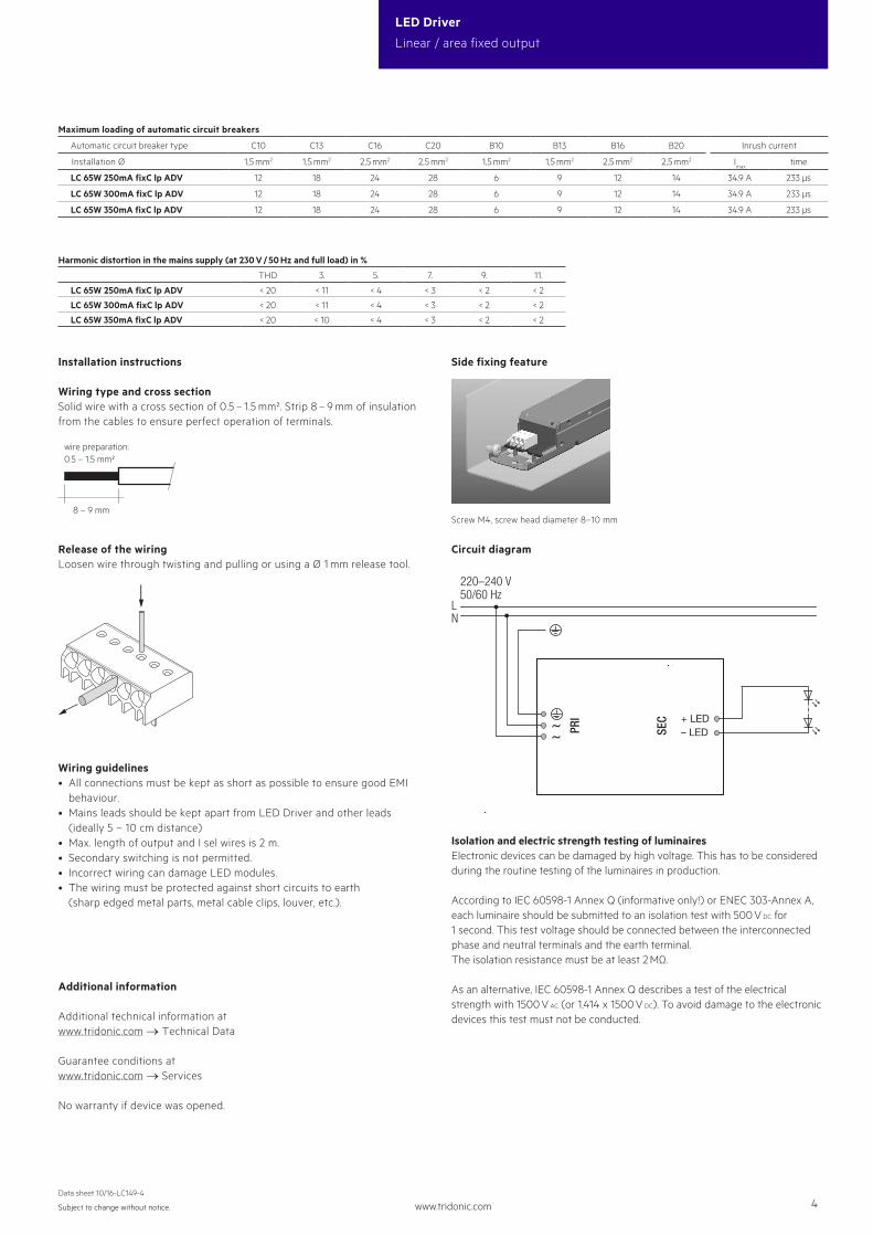
Installation instructions
Wiring type and cross sectionSolid wire with a cross section of 0.5 – 1.5 mm². Strip 8 – 9 mm of insulation from the cables to ensure perfect operation of terminals.
8 – 9 mm
wire preparation:0.5 – 1.5 mm²
Release of the wiringLoosen wire through twisting and pulling or using a Ø 1 mm release tool.
Wiring guidelines• All connections must be kept as short as possible to ensure good EMI
behaviour.• Mains leads should be kept apart from LED Driver and other leads (ideally 5 – 10 cm distance)• Max. length of output and I sel wires is 2 m.• Secondary switching is not permitted.• Incorrect wiring can damage LED modules.• The wiring must be protected against short circuits to earth (sharp edged metal parts, metal cable clips, louver, etc.).
Circuit diagram
Harmonic distortion in the mains supply (at 230 V / 50 Hz and full load) in %
THD 3. 5. 7. 9. 11.
LC 65W 250mA fixC lp ADV < 20 < 11 < 4 < 3 < 2 < 2
LC 65W 300mA fixC lp ADV < 20 < 11 < 4 < 3 < 2 < 2
LC 65W 350mA fixC lp ADV < 20 < 10 < 4 < 3 < 2 < 2
SEC
PRI
220–240 V
LN
50/60 Hz
+ LED– LED
Side fixing feature
Screw M4, screw head diameter 8–10 mm
www.tridonic.com 5Subject to change without notice.
Data sheet 10/16-LC149-4
LED Driver
Linear / area fixed output
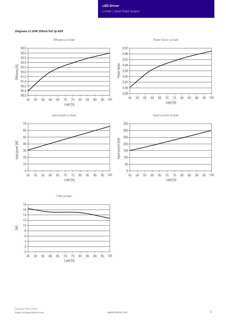
THD vs load
0
4
2
8
18
45 80 85 90 9565 70 7550 55 60 100
16
14
12
10
6
Load [%]
THD
Efficiency vs load
89,590,090,591,091,592,092,5
93,093,594,0
45 70 75 80 85 90 9550 55 60 65 100
94,5
Load [%]
Eci
ency
[%]
Power factor vs load
Diagrams LC 65W 250mA fixC lp ADV
0,89
0,90
0,91
0,92
0,94
0,96
0,95
0,93
0,97
45 70 75 80 85 90 9550 55 60 65 100
Load [%]
Pow
er fa
ctor
Input power vs load
0
10
50
70
45 80 85 90 9565 70 7550 55 60 100
60
20
30
40
Load [%]
Inpu
t pow
er [W
]
Input current vs load
0
150
50
250
350
45 80 85 90 9565 70 7550 55 60 100
300
200
100
Load [%]
Inpu
t cur
rent
[mA]

www.tridonic.com 6Subject to change without notice.
Data sheet 10/16-LC149-4
LED Driver
Linear / area fixed output
THD vs load
0
4
2
8
16
45 80 85 90 9565 70 7550 55 60 100
14
10
12
6
Load [%]
THD
Efficiency vs load
88,0
89,089,5
88,5
90,090,591,091,592,092,593,093,5
45 70 75 80 85 90 9550 55 60 65 100
94,0
Load [%]
Eci
ency
[%]
Power factor vs load
Diagrams LC 65W 300mA fixC lp ADV
0,89
0,90
0,91
0,92
0,93
0,95
0,96
0,97
0,94
0,98
45 70 75 80 85 90 9550 55 60 65 100
Load [%]
Pow
er fa
ctor
Input power vs load
0
10
50
80
45 80 85 90 9565 70 7550 55 60 100
60
70
20
30
40
Load [%]
Inpu
t pow
er [W
]
Input current vs load
0
150
50
250
350
45 80 85 90 9565 70 7550 55 60 100
300
200
100
Load [%]
Inpu
t cur
rent
[mA]

www.tridonic.com 7Subject to change without notice.
Data sheet 10/16-LC149-4
LED Driver
Linear / area fixed output
THD vs load
0
4
2
8
16
45 80 85 90 9565 70 7550 55 60 100
10
12
14
6
Load [%]
THD
Efficiency vs load
88,088,589,089,590,090,591,091,592,092,593,0
45 70 75 80 85 90 9550 55 60 65 100
93,5
Load [%]
Eci
ency
[%]
Power factor vs load
Diagrams LC 65W 350mA fixC lp ADV
0,90
0,91
0,92
0,93
0,94
0,96
0,97
0,95
0,98
45 70 75 80 85 90 9550 55 60 65 100
Load [%]
Pow
er fa
ctor
Input power vs load
0
10
40
80
45 80 85 90 9565 70 7550 55 60 100
50
60
70
20
30
Load [%]
Inpu
t pow
er [W
]
Input current vs load
0
150
50
250
350
45 80 85 90 9565 70 7550 55 60 100
300
200
100
Load [%]
Inpu
t cur
rent
[mA]