Lecture on CE 4014 Design of Concrete Structures Yangon Technological University Department of Civil...
31
Lecture on Lecture on CE 4014 CE 4014 Design of Concrete Design of Concrete Structures Structures Yangon Technological Yangon Technological University University Department of Civil Department of Civil Engineering Engineering Dr. Khin Than Yu Dr. Khin Than Yu Professor and Head Professor and Head (Bond, Anchorage and Development (Bond, Anchorage and Development Length) Length) Part (I) Part (I) 20-3-2008 20-3-2008
-
Upload
bertram-wilkerson -
Category
Documents
-
view
249 -
download
22
Transcript of Lecture on CE 4014 Design of Concrete Structures Yangon Technological University Department of Civil...
Lecture onLecture on
CE 4014CE 4014 Design of Concrete StructuresDesign of Concrete Structures
Yangon Technological UniversityYangon Technological University
Department of Civil EngineeringDepartment of Civil Engineering
Dr. Khin Than YuDr. Khin Than YuProfessor and HeadProfessor and Head
(Bond, Anchorage and Development (Bond, Anchorage and Development Length) Length)
Part (I)Part (I)
20-3-200820-3-2008
Department of Civil Engineering, YTU
2
Design of Concrete StructuresDesign of Concrete Structures
Text and Reference Text and Reference

Department of Civil Engineering, YTU
3
FUNDAMENTALS OF FLEXURAL BONDFUNDAMENTALS OF FLEXURAL BOND
In reinforced concrete In reinforced concrete beams it is assumed that beams it is assumed that strain in the embedded strain in the embedded reinforcing bar is the same reinforcing bar is the same as that in the surrounding as that in the surrounding concrete.concrete.
Therefore, it is essential Therefore, it is essential that bond force is that bond force is developed on the interface developed on the interface between concrete and between concrete and steel to prevent significant steel to prevent significant slip from occurring at the slip from occurring at the interface.interface.

Department of Civil Engineering, YTU
4
Source of bond strengthSource of bond strength
Weak chemical adhesionWeak chemical adhesion Mechanical friction between Mechanical friction between
steel and concretesteel and concrete Slip induced interlocking of Slip induced interlocking of
natural roughness of the natural roughness of the bar with concretebar with concrete
End anchorage, hooks : End anchorage, hooks : providing providing tie arch actiontie arch action even for bond broken beam.even for bond broken beam. Force in the steel, Force in the steel, T = MT = Mmax max / z/ z
Deformed bar: providing Deformed bar: providing bond force via the bond force via the shoulders of the projecting shoulders of the projecting ribs bear on the ribs bear on the surrounding concrete. surrounding concrete.
Department of Civil Engineering, YTU
5
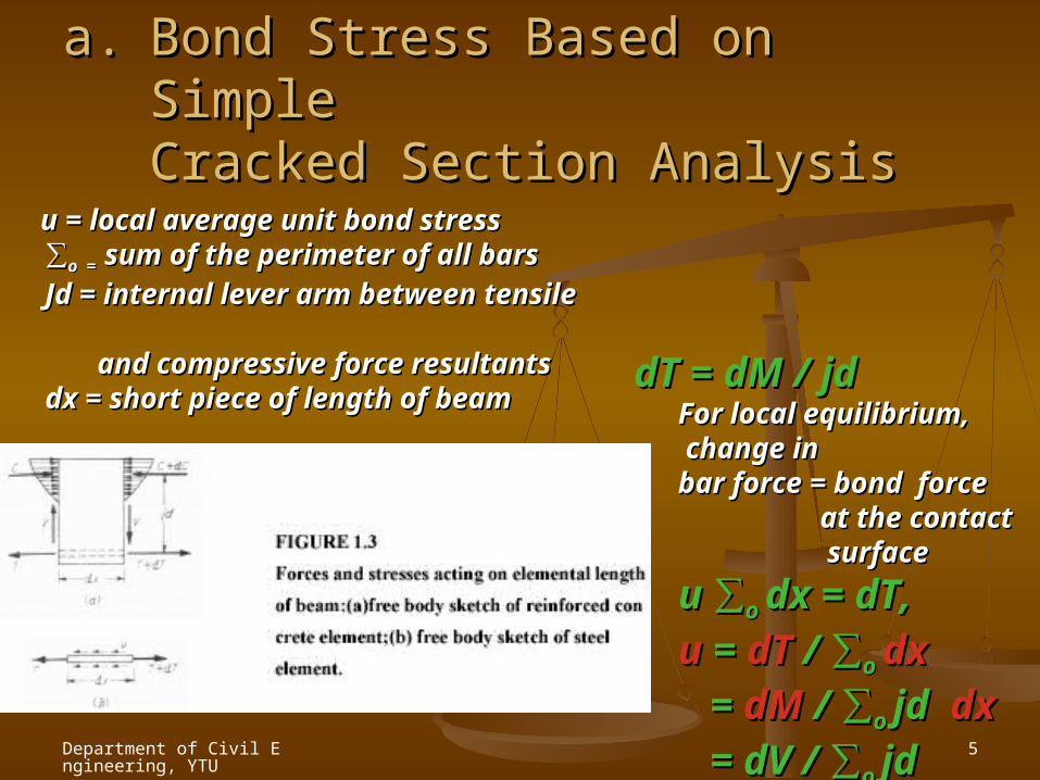
a.a. Bond Stress Based on Simple Bond Stress Based on Simple Cracked Section AnalysisCracked Section Analysis
dT = dM / jddT = dM / jdFor local equilibrium, For local equilibrium, change in change in bar force = bond force bar force = bond force at the contact at the contact surface surface
u u ∑∑o o dx = dT, dx = dT,
uu = = dT dT / ∑/ ∑o o dxdx
= = dM dM / ∑/ ∑o o jd jd dxdx
= dV / ∑ = dV / ∑o o jdjd
u = local average unit bond stressu = local average unit bond stress∑∑o = o = sum of the perimeter of all barssum of the perimeter of all bars
Jd = internal lever arm between tensile Jd = internal lever arm between tensile and compressive force resultants and compressive force resultantsdx = short piece of length of beamdx = short piece of length of beam

Department of Civil Engineering, YTU
6
b. Actual Distribution of Flexural Bond b. Actual Distribution of Flexural Bond StressStress
Pure bending casePure bending case Concrete fails to resist tensile Concrete fails to resist tensile
stresses only where the actual stresses only where the actual crack is located. Steel T is crack is located. Steel T is maximum and maximum and
TT max max = M / jd .= M / jd . Between cracks , concrete Between cracks , concrete
does resist moderate amount does resist moderate amount of tension introduced by bond.of tension introduced by bond.
uu is proportional to the rate of is proportional to the rate of change of bar force, and change of bar force, and highest where the slope of the highest where the slope of the steel force curve is greatest.steel force curve is greatest.
Very high local bond stress Very high local bond stress adjacent to the crack.adjacent to the crack.

Department of Civil Engineering, YTU
7
Beam under transverse loads,Beam under transverse loads, According to simple crack According to simple crack
sectional theory, T is sectional theory, T is proportional to the moment proportional to the moment diagram and u is proportional to diagram and u is proportional to shear force diagram.shear force diagram.
In actual, T is less than the In actual, T is less than the simple analysis prediction simple analysis prediction everywhere except at the everywhere except at the actual cracks. actual cracks.
Similarly, u is equal with simple Similarly, u is equal with simple analysis prediction only at the analysis prediction only at the location where slopes of the location where slopes of the steel force diagrams are steel force diagrams are equals .If the slope is greater equals .If the slope is greater than assumed, bond stress is than assumed, bond stress is greater; if the slope is less bond greater; if the slope is less bond stress is less.stress is less.

Department of Civil Engineering, YTU
8
ULTIMATE BOND STRENGTH AND ULTIMATE BOND STRENGTH AND DEVELOPMENT LENGTHDEVELOPMENT LENGTH
Types of bond failureTypes of bond failure
Direct pulloutDirect pullout of bars of bars (small diameter bars are (small diameter bars are
used with sufficiently used with sufficiently large concrete cover large concrete cover distances and bar distances and bar spacing)spacing)
Splitting of the Splitting of the concreteconcrete along the bar along the bar (cover or bar spacing is (cover or bar spacing is insufficient to resist the insufficient to resist the lateral concrete tension lateral concrete tension resulting from the resulting from the wedging effect of bar wedging effect of bar deformations)deformations)
Department of Civil Engineering, YTU
9
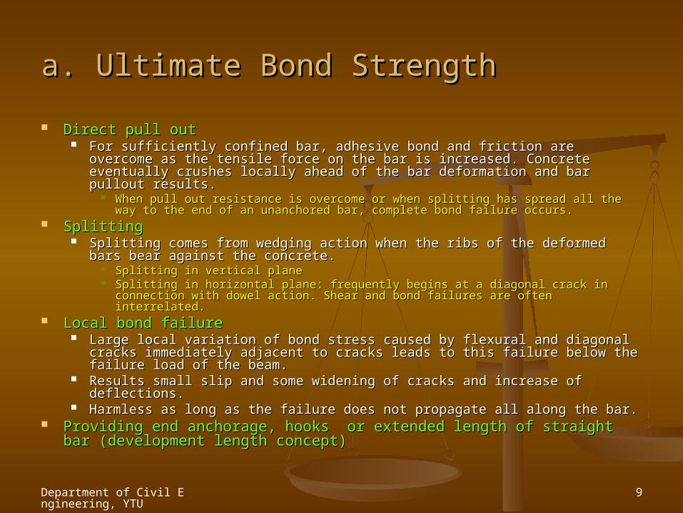
a. Ultimate Bond Strengtha. Ultimate Bond Strength
Direct pull outDirect pull out For sufficiently confined bar, adhesive bond and friction are overcome as For sufficiently confined bar, adhesive bond and friction are overcome as
the tensile force on the bar is increased. Concrete eventually crushes the tensile force on the bar is increased. Concrete eventually crushes locally ahead of the bar deformation and bar pullout results.locally ahead of the bar deformation and bar pullout results.
When pull out resistance is overcome or when splitting has spread all the way When pull out resistance is overcome or when splitting has spread all the way to the end of an unanchored bar, complete bond failure occurs.to the end of an unanchored bar, complete bond failure occurs.
SplittingSplitting Splitting comes from wedging action when the ribs of the deformed bars Splitting comes from wedging action when the ribs of the deformed bars
bear against the concrete.bear against the concrete. Splitting in vertical planeSplitting in vertical plane Splitting in horizontal plane: frequently begins at a diagonal crack in Splitting in horizontal plane: frequently begins at a diagonal crack in
connection with dowel action. Shear and bond failures are often interrelated.connection with dowel action. Shear and bond failures are often interrelated. Local bond failureLocal bond failure
Large local variation of bond stress caused by flexural and diagonal Large local variation of bond stress caused by flexural and diagonal cracks immediately adjacent to cracks leads to this failure below the cracks immediately adjacent to cracks leads to this failure below the failure load of the beam.failure load of the beam.
Results small slip and some widening of cracks and increase of Results small slip and some widening of cracks and increase of deflections.deflections.
Harmless as long as the failure does not propagate all along the bar.Harmless as long as the failure does not propagate all along the bar. Providing end anchorage, hooks or extended length of straight bar Providing end anchorage, hooks or extended length of straight bar
(development length concept)(development length concept)

Department of Civil Engineering, YTU
10
b. Development Lengthb. Development Length
Development lengthDevelopment length is the length of embedment necessary to develop the full tensile strength of bar, is the length of embedment necessary to develop the full tensile strength of bar, controlled by either pullout or splitting.controlled by either pullout or splitting.
In Fig., letIn Fig., let maximum M at a and zero at supportmaximum M at a and zero at support fs at fs at aa T = AT = Abb f fss _ _
Development length conceptDevelopment length concept total tension force must be transferred from the bar to the total tension force must be transferred from the bar to the concrete in the distance ‘concrete in the distance ‘ll ‘ by bond stress on the surface. ‘ by bond stress on the surface.
To fully develop the strength To fully develop the strength T = AT = Abb f fyy lld d , , development lengthdevelopment length
Safety against bond failureSafety against bond failure: the length of the bar from any point of given steel stress to its nearby end : the length of the bar from any point of given steel stress to its nearby end must be at least equal to its development length. If the length is inadequate, special anchorage can be must be at least equal to its development length. If the length is inadequate, special anchorage can be provided.provided.
Department of Civil Engineering, YTU
11
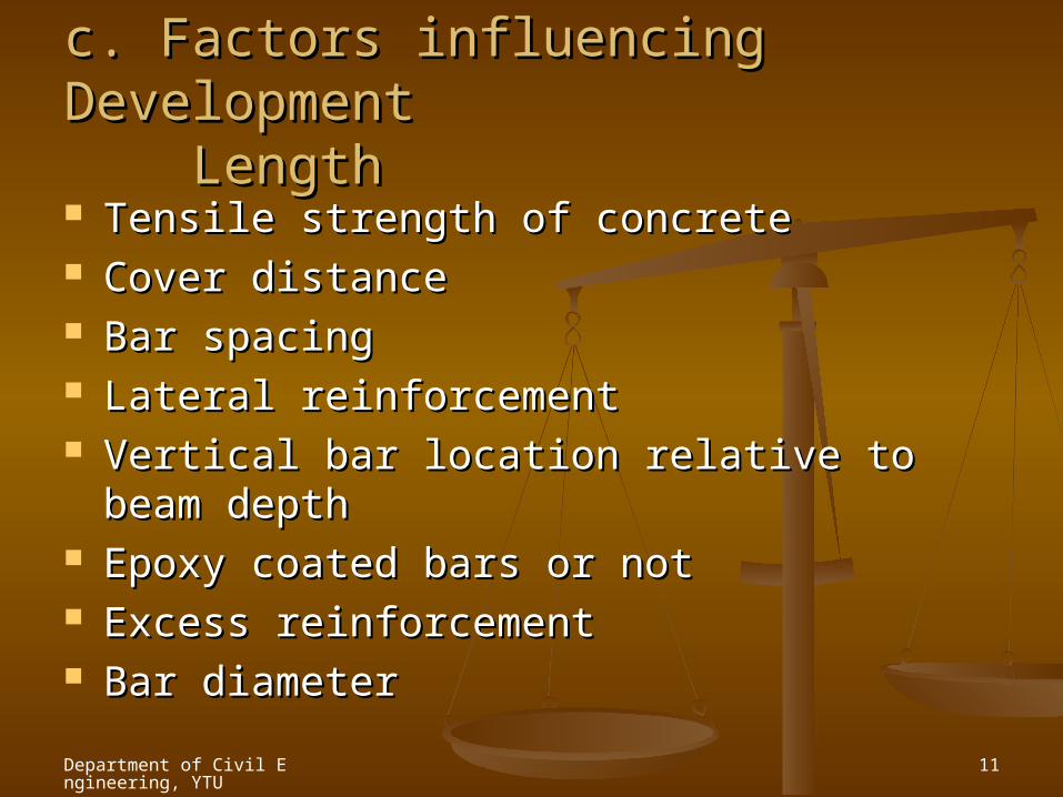
c. Factors influencing Development c. Factors influencing Development Length Length Tensile strength of concreteTensile strength of concrete Cover distanceCover distance Bar spacingBar spacing Lateral reinforcementLateral reinforcement Vertical bar location relative to beam Vertical bar location relative to beam
depthdepth Epoxy coated bars or notEpoxy coated bars or not Excess reinforcementExcess reinforcement Bar diameterBar diameter

Department of Civil Engineering, YTU
12
ACI CODE PROVISION FOR DEVELOPMENT ACI CODE PROVISION FOR DEVELOPMENT OF TENSION REINFORCEMENTOF TENSION REINFORCEMENT
LimitLimit (c + k(c + ktrtr) / d) / dbb = 2.5 for pullout case = 2.5 for pullout case √√f’c are not to be greater than 100 f’c are not to be greater than 100
psi.psi.
Department of Civil Engineering, YTU
13
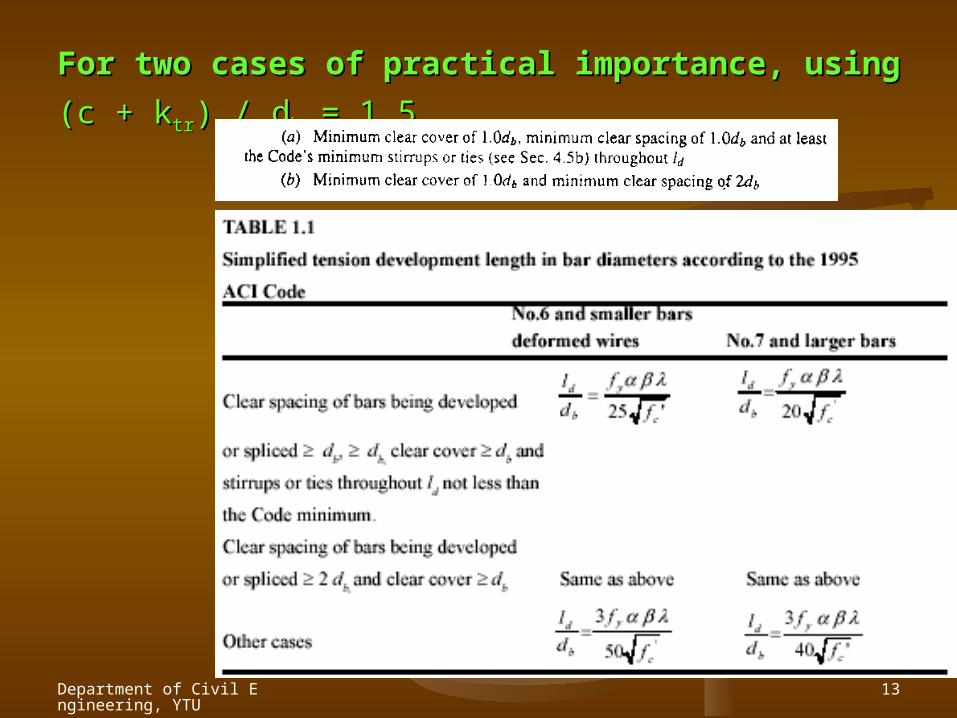
For two cases of practical importance, using For two cases of practical importance, using (c + k(c + ktrtr) / d) / dbb
= 1.5,= 1.5,
Department of Civil Engineering, YTU
14
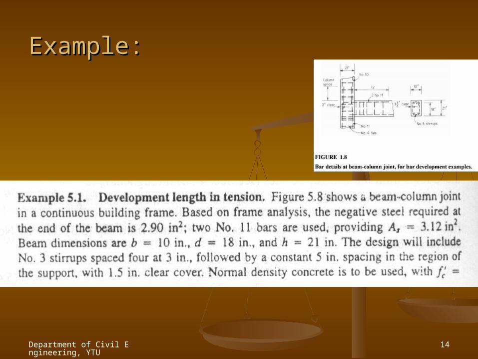
Example:Example:
Department of Civil Engineering, YTU
15
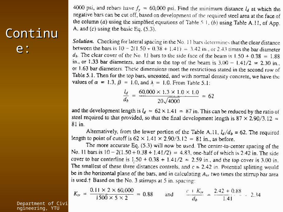
ContinuContinue:e:
Department of Civil Engineering, YTU
16
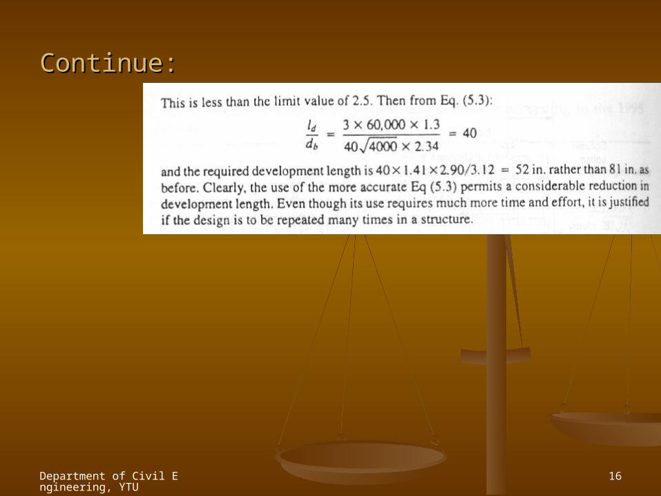
Continue:Continue:
Department of Civil Engineering, YTU
17
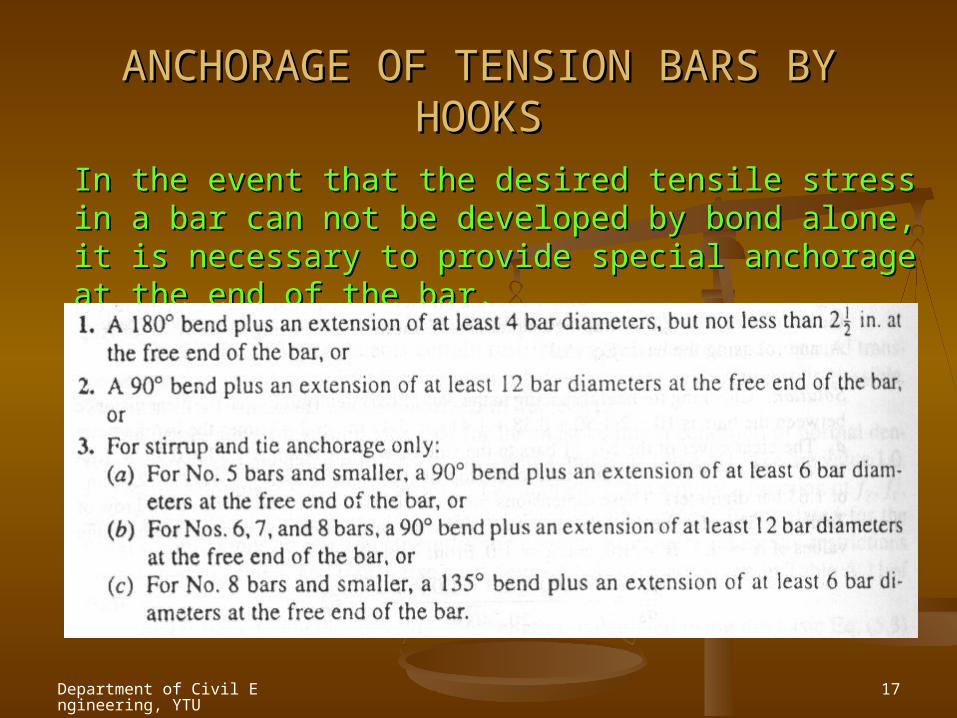
ANCHORAGE OF TENSION BARS BY ANCHORAGE OF TENSION BARS BY HOOKSHOOKS
In the event that the desired tensile stress in a bar can not In the event that the desired tensile stress in a bar can not be developed by bond alone, it is necessary to provide be developed by bond alone, it is necessary to provide special anchorage at the end of the bar.special anchorage at the end of the bar.

Department of Civil Engineering, YTU
18
Department of Civil Engineering, YTU
19
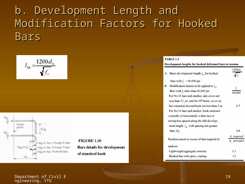
b. Development Length and Modification b. Development Length and Modification Factors for Hooked BarsFactors for Hooked Bars
Department of Civil Engineering, YTU
20
Department of Civil Engineering, YTU
21
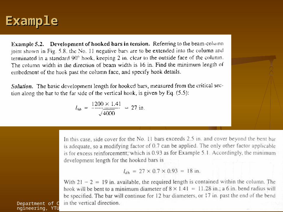
ExampleExample
Department of Civil Engineering, YTU
22
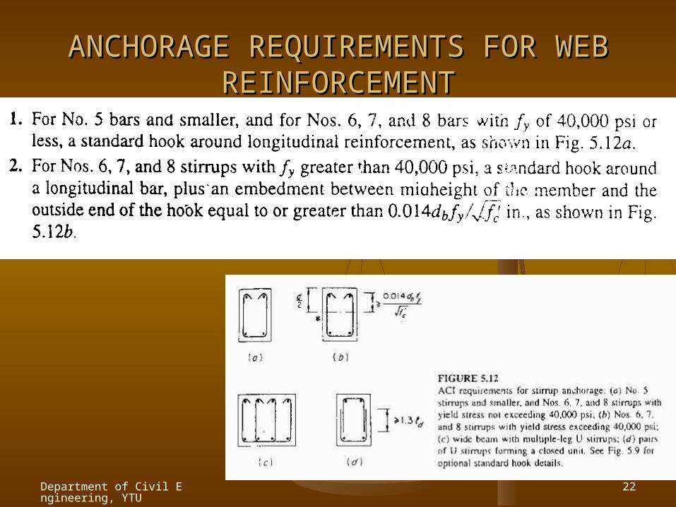
ANCHORAGE REQUIREMENTS FOR WEB ANCHORAGE REQUIREMENTS FOR WEB REINFORCEMENTREINFORCEMENT
Department of Civil Engineering, YTU
23
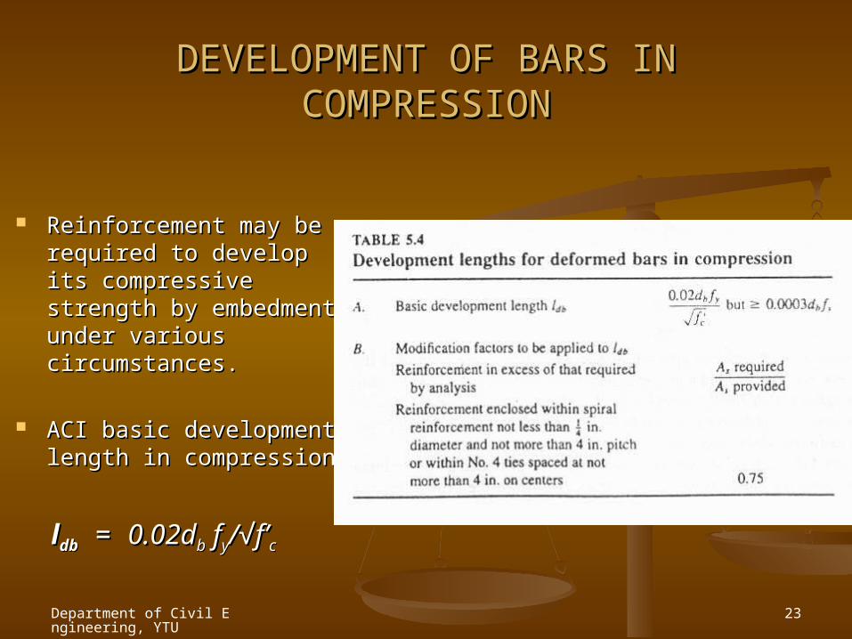
DEVELOPMENT OF BARS IN DEVELOPMENT OF BARS IN COMPRESSIONCOMPRESSION
Reinforcement may be Reinforcement may be required to develop its required to develop its compressive strength compressive strength by embedment under by embedment under various circumstances.various circumstances.
ACI basic development ACI basic development length in compressionlength in compression
lldbdb = = 0.02d0.02dbb f fyy/√f’/√f’cc

Department of Civil Engineering, YTU
24
BAR CUTOFF AND BEND POINTS IN BEAMSBAR CUTOFF AND BEND POINTS IN BEAMS
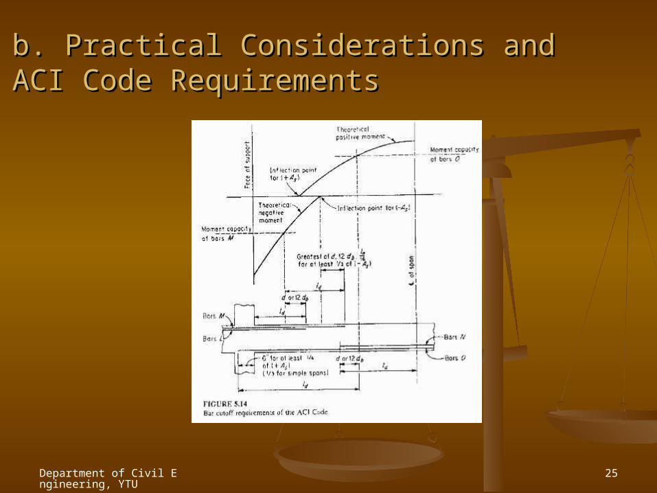
Theoretical points of cutoff Theoretical points of cutoff or bendor bend T = As fs = M/zT = As fs = M/z T = function of (M)T = function of (M)
ACI Code: uniformly loaded, ACI Code: uniformly loaded, continuous beam of fairly continuous beam of fairly regular span may be regular span may be designed using moment designed using moment coefficients.coefficients.
Department of Civil Engineering, YTU
25
b. Practical Considerations and ACI Code b. Practical Considerations and ACI Code RequirementsRequirements
Department of Civil Engineering, YTU
26
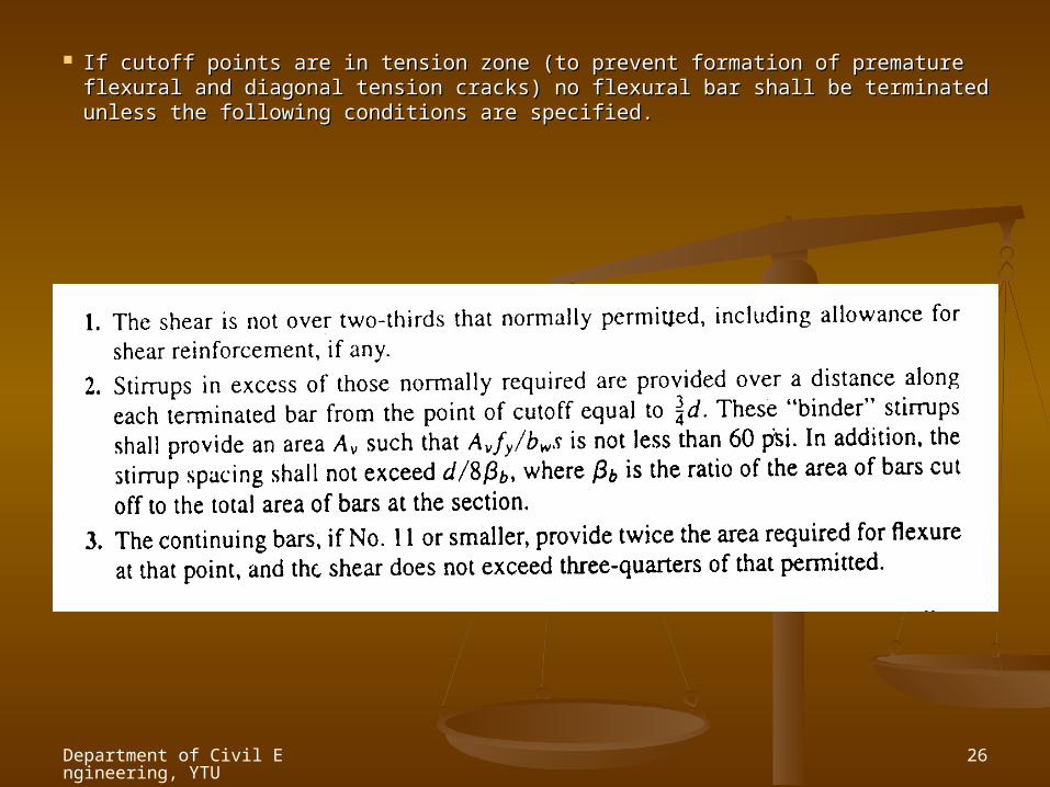
If cutoff points are in tension zone (to prevent formation of premature flexural and If cutoff points are in tension zone (to prevent formation of premature flexural and diagonal tension cracks) no flexural bar shall be terminated unless the following diagonal tension cracks) no flexural bar shall be terminated unless the following conditions are specified.conditions are specified.
Department of Civil Engineering, YTU
27
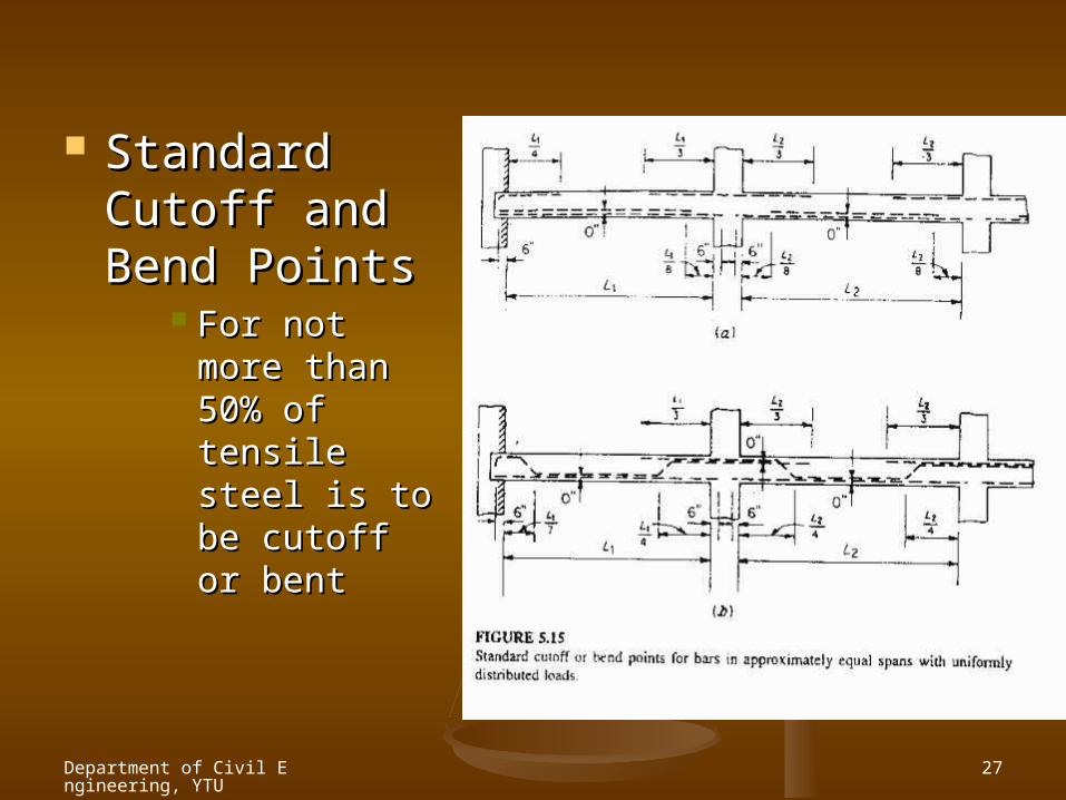
Standard Standard Cutoff and Cutoff and Bend PointsBend Points
For not more For not more than 50% of than 50% of tensile steel tensile steel is to be cutoff is to be cutoff or bentor bent
Department of Civil Engineering, YTU
28
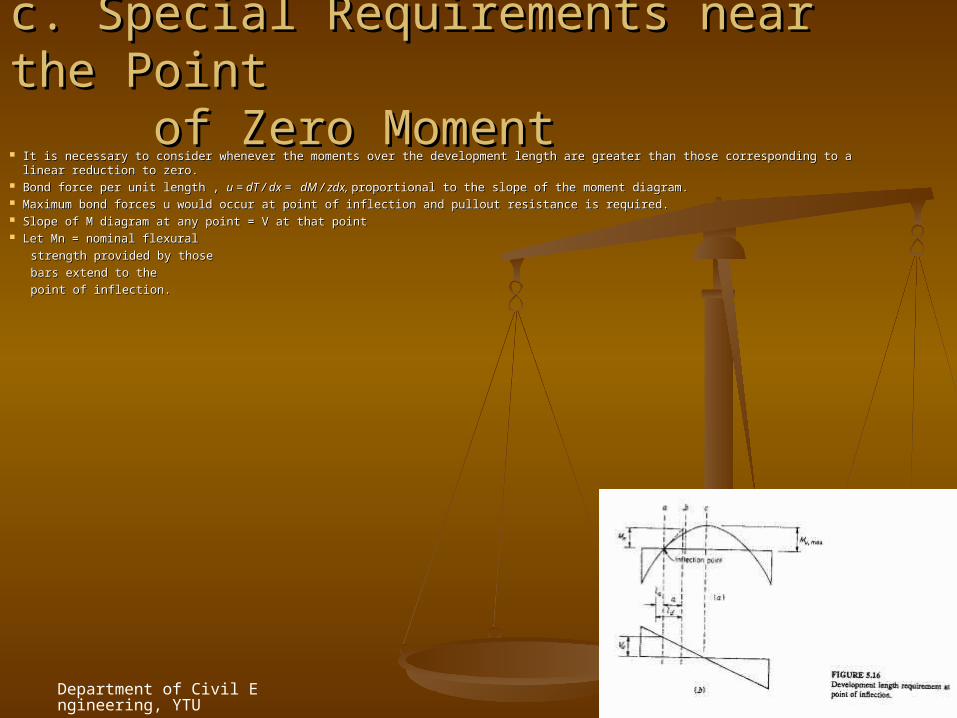
c. Special Requirements near the Point c. Special Requirements near the Point
of Zero Moment of Zero Moment It is necessary to consider whenever the moments over the development length are greater than those corresponding to a linear reduction to It is necessary to consider whenever the moments over the development length are greater than those corresponding to a linear reduction to
zero.zero. Bond force per unit length , Bond force per unit length , u = dT / dx = dM / zdx, u = dT / dx = dM / zdx, proportional to the slope of the moment diagram.proportional to the slope of the moment diagram. Maximum bond forces u would occur at point of inflection and pullout resistance is required.Maximum bond forces u would occur at point of inflection and pullout resistance is required. Slope of M diagram at any point = V at that pointSlope of M diagram at any point = V at that point Let Mn = nominal flexural Let Mn = nominal flexural
strength provided by thosestrength provided by those
bars extend to thebars extend to the
point of inflection.point of inflection.
Department of Civil Engineering, YTU
29
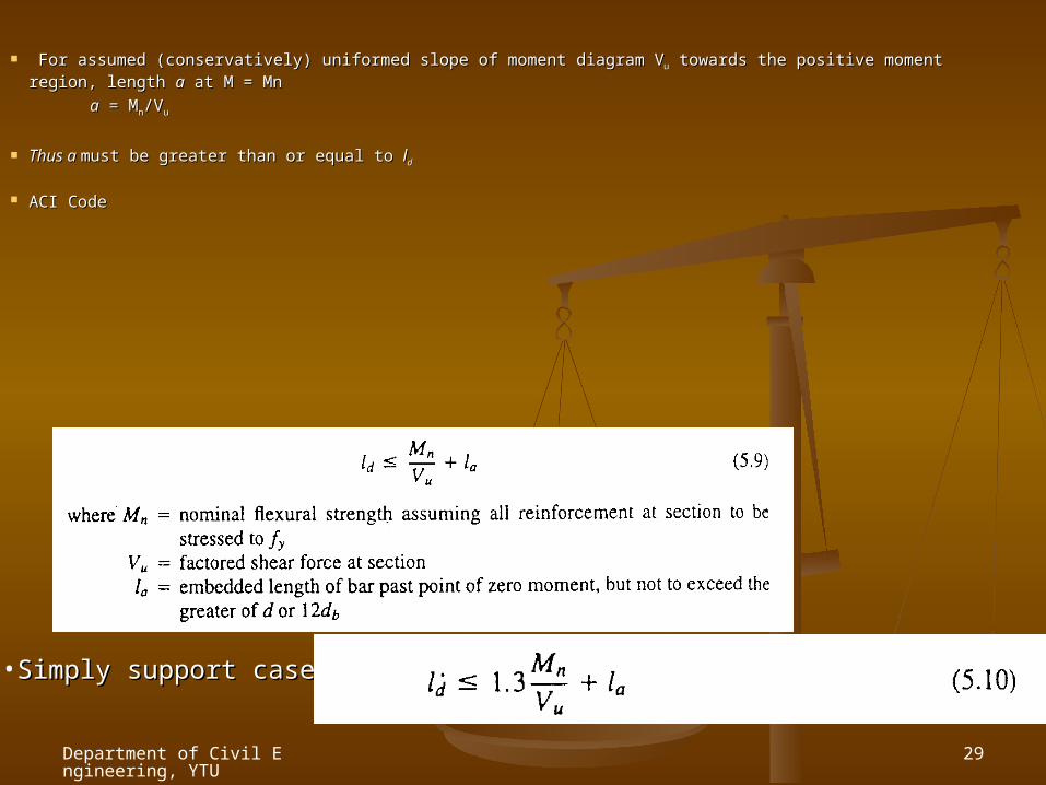
For assumed (conservatively) uniformed slope of moment diagram VFor assumed (conservatively) uniformed slope of moment diagram V uu towards the positive moment region, towards the positive moment region, length length aa at M = Mn at M = Mn
aa = M = Mnn/V/Vu u
Thus a Thus a must be greater than or equal to must be greater than or equal to lldd
ACI CodeACI Code
•Simply support caseSimply support case
Department of Civil Engineering, YTU
30
d. Structural Integrity Provisionsd. Structural Integrity Provisions
For major supporting elements, such as columns, For major supporting elements, such as columns, total collapse can be prevented through relatively total collapse can be prevented through relatively minor changes in bar detailing owing to minor changes in bar detailing owing to accidental or abnormal loading.accidental or abnormal loading.
If some reinforcement properly confined is carried If some reinforcement properly confined is carried continuously through a support catenary action of continuously through a support catenary action of beam can prevent from total collapse even if the beam can prevent from total collapse even if the support is damaged.support is damaged.
ACI CodeACI Code

Department of Civil Engineering, YTU
31
CommentComment
Consideration for bond and detail Consideration for bond and detail design for anchorage, development design for anchorage, development length and structural integrity length and structural integrity requirements are important to have requirements are important to have proper structural performance of the proper structural performance of the building.building.