Lecture 7 Neutron Detection - MIT OpenCourseWare Counter • Proportional region – Electric field...
49
Lecture 7 Neutron Detection 22.106 Neutron Interactions and Applications Spring 2010
Transcript of Lecture 7 Neutron Detection - MIT OpenCourseWare Counter • Proportional region – Electric field...

Lecture 7Neutron Detection
22.106 Neutron Interactions and ApplicationsSpring 2010

Types of detectors
• Gas-filled detectors consist of a volume of gas between two electrodes
• In scintillation detectors, the interaction of ionizing radiation produces UV and/or visible light
• Semiconductor detectors are especially pure crystals of silicon, germanium, or other materials to which trace amounts of impurity atoms have been added so that they act as diodes

Types of detectors (cont.)• Detectors may also be classified by the type of
information produced:– Detectors, such as Geiger-Mueller (GM) detectors,
that indicate the number of interactions occurring in the detector are called counters
– Detectors that yield information about the energy distribution of the incident radiation, such as NaI scintillation detectors, are called spectrometers
– Detectors that indicate the net amount of energy deposited in the detector by multiple interactions are called dosimeters
Modes of operation
• In pulse mode, the signal from each interaction is processed individually
• In current mode, the electrical signals from individual interactions are averaged together, forming a net current signal

Interaction rate
• Main problem with detectors in pulse mode is that two interactions must be separated by a finite amount of time if they are to produce distinct signals– This interval is called the dead time of the system
• If a second interaction occurs in this interval, its signal will be lost; if it occurs close enough to the first interaction, it may distort the signal from the first interaction– Show figure p.120

Dead time
• Dead time of a detector system largely determined by the component in the series with the longest dead time– Detector has longest dead time in GM counter
systems– In multichannel analyzer systems the analog-to-digital
converter often has the longest dead time• GM counters have dead times ranging from tens
to hundreds of microseconds, most other systems have dead times of less than a few microseconds

Paralyzable or nonparalyzable
• In a paralyzable system, an interaction that occurs during the dead time after a previous interaction extends the dead time
• In a nonparalyzable system, it does not• At very high interaction rates, a
paralyzable system will be unable to detect any interactions after the first, causing the detector to indicate a count rate of zero

τ
τ
Dead Live
Dead Live
Paralyzable
Nonparalyzable
Time Events in detector
Image by MIT OpenCourseWare.

Interaction Rate
50,00040,00030,00020,00010,0000
Cou
nt R
ate
0
2000
4000
6000
8000
10,000
IdealNon-paralyzableParalyzable
Image by MIT OpenCourseWare.

Current mode operation
• In current mode, all information regarding individual interactions is lost
• If the amount of electrical charge collected from each interaction is proportional to the energy deposited by that interaction, then the net current is proportional to the dose rate in the detector material
• Used for detectors subjected to very high interaction rates

Spectroscopy• Most spectrometers operate in pulse mode• Amplitude of each pulse is proportional to the
energy deposited in the detector by the interaction causing that pulse
• The energy deposited by an interaction is not always the total energy of the incident particle or photon
• A pulse height spectrum is usually depicted as a graph of the number of interactions depositing a particular amount of energy in the spectrometer as a function of energy

700600500400
Energy (keV)
3002001000
Num
ber o
f Int
erac
tions
32 keV
662 keV
Energy (keV)
7006005004003002001000
100
Rel
ativ
e nu
mbe
r of p
hoto
ns32 keV
662 keV
Image by MIT OpenCourseWare.

Detection efficiency
• The efficiency (sensitivity) of a detector is a measure of its ability to detect radiation
• Efficiency of a detection system operated in pulse mode is defined as the probability that a particle or photon emitted by a source will be detected

efficiency Intrinsic efficiency Geometric Efficiencydetector reachingNumber
detectedNumber
emittedNumber detector reachingNumber Efficiency
emittedNumber detectedNumber Efficiency
×=
×=
=
A
aS
Ω
d
Image by MIT OpenCourseWare.
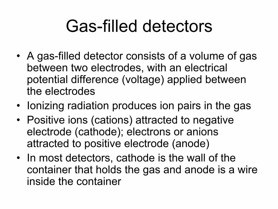
Gas-filled detectors• A gas-filled detector consists of a volume of gas
between two electrodes, with an electrical potential difference (voltage) applied between the electrodes
• Ionizing radiation produces ion pairs in the gas• Positive ions (cations) attracted to negative
electrode (cathode); electrons or anions attracted to positive electrode (anode)
• In most detectors, cathode is the wall of the container that holds the gas and anode is a wire inside the container

• Outer shell is a metal cylinder made of either Steel or Aluminum– Filled with a gas
• Inner wire is gold plated tungsten– Tungsten provides strength to the thin wire– Gold provides improved conductivity
Incidentchargedparticle
Anode (+)
Cathode (-)
Battery or power supply
Meter
+ + + + + +-
-- - -
-
Image by MIT OpenCourseWare.

Types of gas-filled detectors• Three types of gas-filled detectors in common
use:– Ionization chambers– Proportional counters– Geiger-Mueller (GM) counters
• Type determined primarily by the voltage applied between the two electrodes
• Ionization chambers have wider range of physical shape (parallel plates, concentric cylinders, etc.)
• Proportional counters and GM counters must have thin wire anode

Ionization Counter
• Ionization region– All electrons are
collected– Charge collected is
proportional to the energy deposited
– Called ion chambers
1012
1010
108
106
104
102
10005000
Puls
e H
eigh
t (A
rbitr
ary
Uni
ts)
Applied Voltage
Geiger-MullerRegion
Proportional Region
Ionization ChamberRegion
RecombinationRegion
Image by MIT OpenCourseWare.
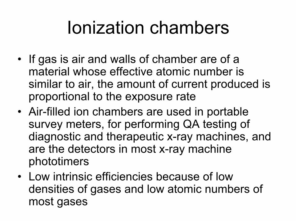
Ionization chambers• If gas is air and walls of chamber are of a
material whose effective atomic number is similar to air, the amount of current produced is proportional to the exposure rate
• Air-filled ion chambers are used in portable survey meters, for performing QA testing of diagnostic and therapeutic x-ray machines, and are the detectors in most x-ray machine phototimers
• Low intrinsic efficiencies because of low densities of gases and low atomic numbers of most gases

Proportional Counter
• Proportional region– Electric field is strong
enough to create secondary ionization
– Further increases create more ionization in the gas
• Avalanche ionization
– Charge collected is linearly proportional to energy deposited
1012
1010
108
106
104
102
10005000
Puls
e H
eigh
t (A
rbitr
ary
Uni
ts)
Applied Voltage
Geiger-MullerRegion
Proportional Region
Ionization ChamberRegion
RecombinationRegion
Image by MIT OpenCourseWare.

Avalanche Ionization
Anode wire
25µm
Image by MIT OpenCourseWare.
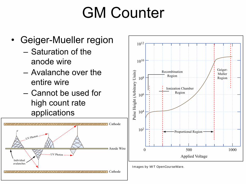
GM Counter
• Geiger-Mueller region– Saturation of the
anode wire– Avalanche over the
entire wire– Cannot be used for
high count rate applications
1012
1010
108
106
104
102
10005000
Puls
e H
eigh
t (A
rbitr
ary
Uni
ts)
Applied Voltage
Geiger-MullerRegion
Proportional Region
Ionization ChamberRegion
RecombinationRegion
Cathode
Cathode
Anode WireUV Photon
UV Photon
Individualavalanches
e
Images by MIT OpenCourseWare.

GM counters• GM counters also must contain gases with
specific properties• Gas amplification produces billions of ion pairs
after an interaction – signal from detector requires little amplification
• Often used for inexpensive survey meters• In general, GM survey meters are inefficient
detectors of x-rays and gamma rays• Over-response to low energy x-rays – partially
corrected by placing a thin layer of higher atomic number material around the detector

GM counters (cont.)
• GM detectors suffer from extremely long dead times – seldom used when accurate measurements are required of count rates greater than a few hundred counts per second
• Portable GM survey meter may become paralyzed in a very high radiation field – should always use ionization chamber instruments for measuring such fields

Neutron Detection
• Neutral particles– Detection is based on indirect interactions
• Two basic interactions– Scattering
• Recoiling nucleus ionizes surrounding material• Only effective with light nucleus (Hydrogen,
Helium)– Nuclear reactions
• Products of the reaction can be detected (gamma, proton, alpha, fission fragments)

Neutron Detection• Since x.s. in most materials are strongly
dependent on neutron energy, different techniques exist for different regions:– Slow neutrons (or thermal neutrons), below
the Cadmium cutoff– Fast neutrons 105
104
103
102
101
100
10-1
10-110-210-310-410-510-610-710-810-9 100 101
Energy (MeV)
Cro
ss S
ectio
n (b
)
Image by MIT OpenCourseWare.

Thermal Neutron Detectors• Two important aspects to consider
– Find a material with large thermal x.s.– Find an arrangement that allows you to
distinguish from gamma rays• High Q-value of neutron capture will make it easier
104
103
102
10-2 10-1 1 101 102 103 104 105 106 107
10
1
10-1
Neutron Energy (eV)
Cro
ss S
ectio
n (b
arns
)
He-3 (n, p)B-10 (n, α)Li-6 (n, α)
Image by MIT OpenCourseWare.

10B(n,alpha)• Equations• 94% of the time in excited state
– Q-value of 2.310 MeV– Other 6%, Q-value of 2.792 MeV
B-10
*Li-7
α
n
(excited)
B-10
Li-7
α
n
Alpha kinetic energy = 1.78 MeVLi-7 kinetic energy = 1.02 MeV
Alpha kinetic energy = 1.47 MeVLi-7 kinetic energy = 0.84 MeV
Image by MIT OpenCourseWare.

BF3 Tube
B-10αLi-7
n
B-10α Li-7
n
The Li-7 deposits all its kinetic energyin the gas while the alpha particledeposits only a fraction of itsenergy.
The alpha particle deposits all its kinetic energy in the gas while the Li-7deposits only a fraction of itsenergy.
Pulse Size (energy deposited in detector)
# Pu
lses
2.31 MeV
2.79 MeV
1.47 MeV0.84 MeV
Gamma raypulse, noise, etc.
Image by MIT OpenCourseWare.
Image by MIT OpenCourseWare.

Efficiency of BF3 Tube
• Intrinsic efficiency– Eff(E) = 1- exp(-Sigma(E) * L)
6Li(n,alpha)
• Equation• Only a ground state exists with Q-value of
4.78 MeV– EHe-3 = 2.73 MeV and Ealpha = 2.05 MeV
• Other possible reactions– 3He(n,p)– 157Gd

Gamma-ray sensitivity
3He (2.5 cm diam, 4 atm)
Ar (2.5 cm diam, 2 atm)
BF3 (5.0 cm diam, 0.66 atm)
Al tube wall (0.8 mm)
4He (5.0 cm diam, 18 atm)
Scintillator (5.0 cm thick)
Al tube wall (0.8 mm)
Thermal Detectors
Fast Detectors
Interaction Probability
Interaction Probability
Thermal Neutron
1 - MeV Gamma Ray
1 - MeV Gamma Ray
1 - MeV Neutron
0.77
0.0
0.29
0.0
0.0001
0.0005
0.0006
0.014
0.01
0.0
0.78
0.001
0.014
0.26
Neutron and gamma-ray interaction probabilities in typical gas proportional counters and scintillators
Image by MIT OpenCourseWare.

Fission chambers
• Inner surface of gas tube is coated with a fissile material (U-235)– Current mode in reactor operation– Pulse mode elsewhere
• Efficiency of about 0.5% at thermal energies• Combine fissile and fertile material to avoid loss
of sensitivity (regenerative chambers)• Memory effect when used in high flux regions
– Decay of FPs
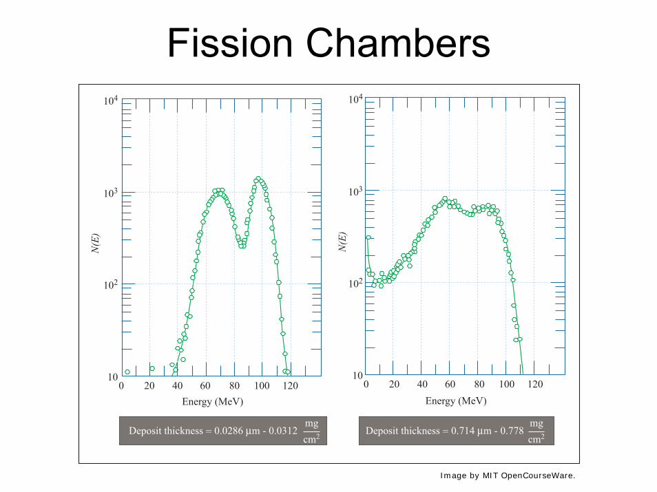
Fission Chambers104
103
102
100 20 40 60 80 100 120
N(E
)
Energy (MeV)
104
103
102
100 20 40 60 80 100 120
N(E
)
Energy (MeV)
Deposit thickness = 0.0286 µm - 0.0312 cm2
mgDeposit thickness = 0.714 µm - 0.778
cm2
mg
Image by MIT OpenCourseWare.

Neutron Spectroscopy
• Bonner Sphere
2" 3" 5" 8" 10" 12" 12" + Pb
12" + Pbinternal part
Image by MIT OpenCourseWare.
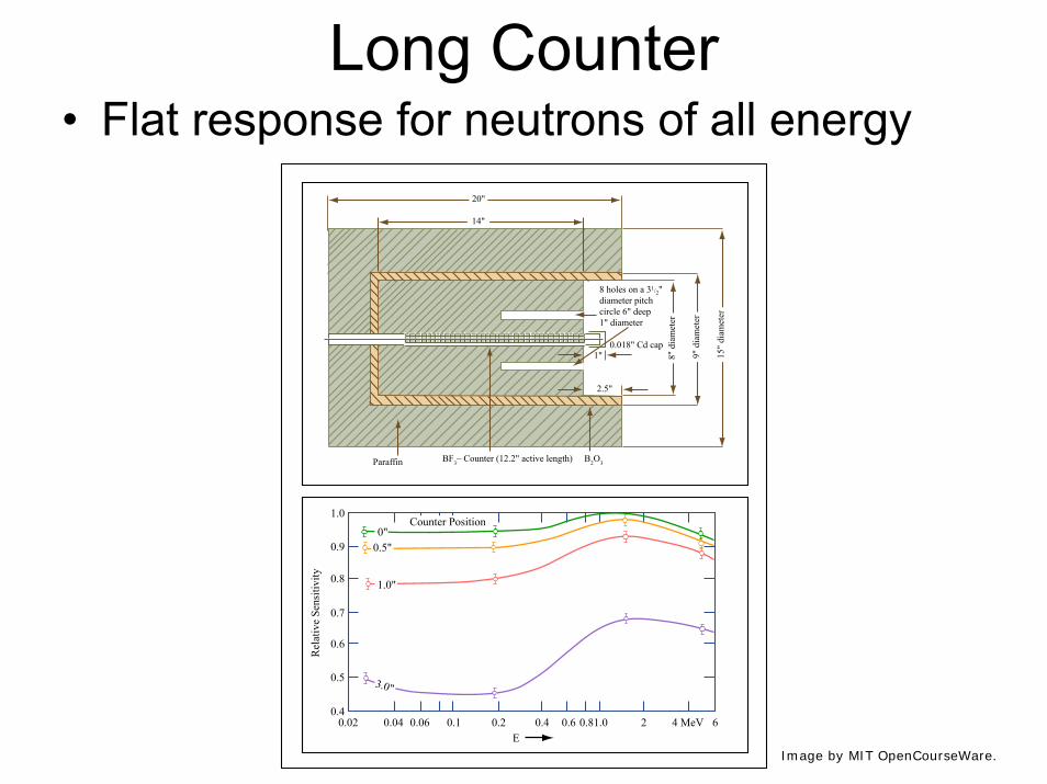
Long Counter• Flat response for neutrons of all energy
Paraffin BF3_ Counter (12.2" active length) B2O3
20"
8 holes on a 31/2"diameter pitchcircle 6" deep1" diameter
0.018" Cd cap
14"
8" d
iam
eter
9" d
iam
eter
15"
diam
eter
1.0
0.9
0.8
0.7
0.6
0.5
0.40.02 0.04 0.06 0.1 0.2 0.4 0.6 0.81.0 2 4 MeV 6
E
Rel
ativ
e Se
nsiti
vity
0"0.5"
1.0"
3.0"
Counter Position
2.5"
1"
Image by MIT OpenCourseWare.

Fast-Neutron induced reaction detectors
• 6Li(n,alpha)– Q-value of 4.78 MeV– Peaks appear at Q-value + neutron kinetic
energy– Lithium based scintillators
1 x 1041 x
10-1
1 x
101
1 x 10⁵ 1 x 10⁶ 1 x 10⁷
1
2 3 4 5 6 7 8 9 2 3 4 5 6 7 8 9 2 3 4 5 6 7 8 9
23
45
67
89
23
45
67
89
Energy [eV]
Cro
ss-s
ectio
n [b
arns
]3He [π, ρ] 6Li [π, α]
Image by MIT OpenCourseWare.

• 3He(n,p)– Energy range 20 keV to 2 MeV
• Smooth, nearly flat x.s.• Tube is wrapped in Cadmium and Boron layersto
reduce contribution from thermal neutrons• Lead shield is also added to reduce impact of
photons• Intrinsic efficiency is very low (0.1%)• Full energy peak at En + 765 keV• Thermal neutron capture peak at 765 keV• Elastic scattering spectrum with a max at 0.75En

0.764 MeV En + 0.764 MeV0.75 En E
En
dNdE
Epithermalpeak
Recoildistribution
Full-energypeak
Image by MIT OpenCourseWare.

Fast Neutron Recoil Detectors
• Most useful reaction is elastic scattering– Recoil nucleus will ionize medium– Most popular target is hydrogen
• Large elastic scattering x.s• Well known x.s.• Neutron can transfer all of its energy
0 1 2 3 4 5 60.1
1
10
100
Fission spectrum shape
4He
1H
Neutron energy (MeV)Sc
atte
ring
cros
s sec
tion
(bar
ns)
in one collision– Q-value is zero
• Information can be found about the incoming neutron energy
Image by MIT OpenCourseWare.

Gas recoil detectors
0.40.6
0.81.0
1.2
1.6
2.0
4He Recoil Pulse Height, MeV
4 He
Wei
ght/M
eV(~
Cou
nts/
Cha
nnel
)
00
10
20
30
0.1 0.2 0.3 0.4 0.5 0.6 0.7 0.8 0.9 1.0 1.1 1.2 1.3 1.4
4He Recoil Pulse Height, MeV
4 He
Wei
ght/M
eV (~
Cou
nts/
Cha
nnel
)
1.6
1.4
1.2
1.0
0.8
0.6
0.4
0.2
00 1 2 3 4 5 6
4.0
6.0
8.0
Incident Neutron Energy (MeV)
4He Recoil Pulse Height, MeV
Incident Neutron Energy (MeV)
Incident Neutron Energy (MeV)
4 He
Wei
ght/M
eV (~
Cou
nts/
Cha
nnel
)
10.012.0
14.0
00
0.1
0.2
0.3
0.4
0.5
0.6
0.7
0.8
1 2 3 4 5 6 7 8 9
Image by MIT OpenCourseWare.

Scintillators• Desirable properties:
– High conversion efficiency– Decay times of excited states should be short– Material transparent to its own emissions– Color of emitted light should match spectral sensitivity
of the light receptor– For x-ray and gamma-ray detectors, μ should be large
– high detection efficiencies– Rugged, unaffected by moisture, and inexpensive to
manufacture

Scintillators (cont.)
• Amount of light emitted after an interaction increases with energy deposited by the interaction
• May be operated in pulse mode as spectrometers
• High conversion efficiency produces superior energy resolution

Materials
• Sodium iodide activated with thallium [NaI(Tl)], coupled to PMTs and operated in pulse mode, is used for most nuclear medicine applications– Fragile and hygroscopic
• Bismuth germanate (BGO) is coupled to PMTs and used in pulse mode as detectors in most PET scanners
Photomultiplier tubes
• PMTs perform two functions:– Conversion of ultraviolet and visible light
photons into an electrical signal– Signal amplification, on the order of millions to
billions• Consists of an evacuated glass tube
containing a photocathode, typically 10 to 12 electrodes called dynodes, and an anode

+100 volts +300 volts
+400 volts+200 volts
Signal topreamp
Visible lightphoton
Glass tube
Anode+500 volts
Photocathode0 volts Dynodes
Image by MIT OpenCourseWare.

Dynodes
• Electrons emitted by the photocathode are attracted to the first dynode and are accelerated to kinetic energies equal to the potential difference between the photocathode and the first dynode
• When these electrons strike the first dynode, about 5 electrons are ejected from the dynode for each electron hitting it
• These electrons are attracted to the second dynode, and so on, finally reaching the anode

PMT amplification
• Total amplification of the PMT is the product of the individual amplifications at each dynode
• If a PMT has ten dynodes and the amplification at each stage is 5, the total amplification will be approximately 10,000,000
• Amplification can be adjusted by changing the voltage applied to the PMT

MIT OpenCourseWarehttp://ocw.mit.edu
22.106 Neutron Interactions and ApplicationsSpring 2010
For information about citing these materials or our Terms of Use, visit: http://ocw.mit.edu/terms.