SOIL 4213 BIOEN 4213 History of Using Indirect Measures for detecting Nutrient Status

Energy Systems Research Laboratory, FIU (c) Copyright by Prof. Osama A. Mohammed. All rights reserved. 5-1
Lecture (5) Power Factor,three-
phase circuits, and Per Unit Calculations

Energy Systems Research Laboratory, FIU (c) Copyright by Prof. Osama A. Mohammed. All rights reserved. 5-2
Make this plant take power at 0.95 p.f. lagging
1000 volts @ 60 Htz
Motor Light
20 kVA 0.7 p.f. lagging
10kW unity p.f.
From source
P = ? Q = ? S = ?
Repeating the Example on Power Factor Correction (Given last Class)

Energy Systems Research Laboratory, FIU (c) Copyright by Prof. Osama A. Mohammed. All rights reserved. 5-3
MOTOR S = 20 ∠ cos -1 (0.7) kVA
= 20 ∠ 45.6 ° kVA P = 20 cos 45.6° kW = 14 kW
Q = 20 sin 45.7 ° = 14.28 kVAR 0 10 j S L + =
Example Solution
kVA
Light

Energy Systems Research Laboratory, FIU (c) Copyright by Prof. Osama A. Mohammed. All rights reserved. 5-4
TOTAL
P = 14 + 10 = 24 Kw Q = 14.28 KVAR
S = KVA 9 . 27 2 28 . 14 2 24 = +
° = = − 75 . 30 24 28 . 14 tan 1 θ
p.f. = cos 30.75° = 0.86 lagging
This is the total for this particular problem, before Power Factor Correction

Energy Systems Research Laboratory, FIU (c) Copyright by Prof. Osama A. Mohammed. All rights reserved. 5-5
Qnew
When Adding a Capacitor
Need a capacitor that produces 6.38 KVAR at 1000 volts
18.19 ° θ new = cos -1 .95 = 18.19 °
Qnew = P (tan 18.19°) = 24 x 103 x tan 18.19° = 7.9 kVAR
Qcap = Qold – Qnew = 14.28 - 7.9 = 6.38 kVAR

Energy Systems Research Laboratory, FIU (c) Copyright by Prof. Osama A. Mohammed. All rights reserved. 5-6
Find the value of capacitance c = ?
2
* * 1
Q V
Q * V V
V Q V
I V
j ω c -jxc = =
= = =
= 2 ω V
Q c = 2 V
Q ω c = 2 V
- jQ - j ω c
( ) = × =
60 2 2
1000
3 10 38 . 6 π
c 16.9 µF

Energy Systems Research Laboratory, FIU (c) Copyright by Prof. Osama A. Mohammed. All rights reserved. 5-7
THREE PHASE CIRCUITS
A → B → C
A B
C
V LN
N V ph = V L
Y-Connection Delta-Connection

Energy Systems Research Laboratory, FIU (c) Copyright by Prof. Osama A. Mohammed. All rights reserved. 5-8
THREE PHASE CIRCUITS
3 phase V =
V ph - ph = V L = V AB = phase to phase (or line voltage)
V phase = = phase to neutral
Y-Connection
S = 3 Vph Iph*
VL
VLN = VAN

Energy Systems Research Laboratory, FIU (c) Copyright by Prof. Osama A. Mohammed. All rights reserved. 5-9
Y-connection
phase V = 3
VAB=VBC=VCA=VL
IL=Iph
N VAB=VAN-VBN
Iph=IL
VL
A
B
C

Energy Systems Research Laboratory, FIU (c) Copyright by Prof. Osama A. Mohammed. All rights reserved. 5-10
∆-connection
3 ph I
ph V
=
=
ph ph I V S * 3 =
IA
IB
IC
IL
VL A
B
C
Energy Systems Research Laboratory, FIU (c) Copyright by Prof. Osama A. Mohammed. All rights reserved. 5-11
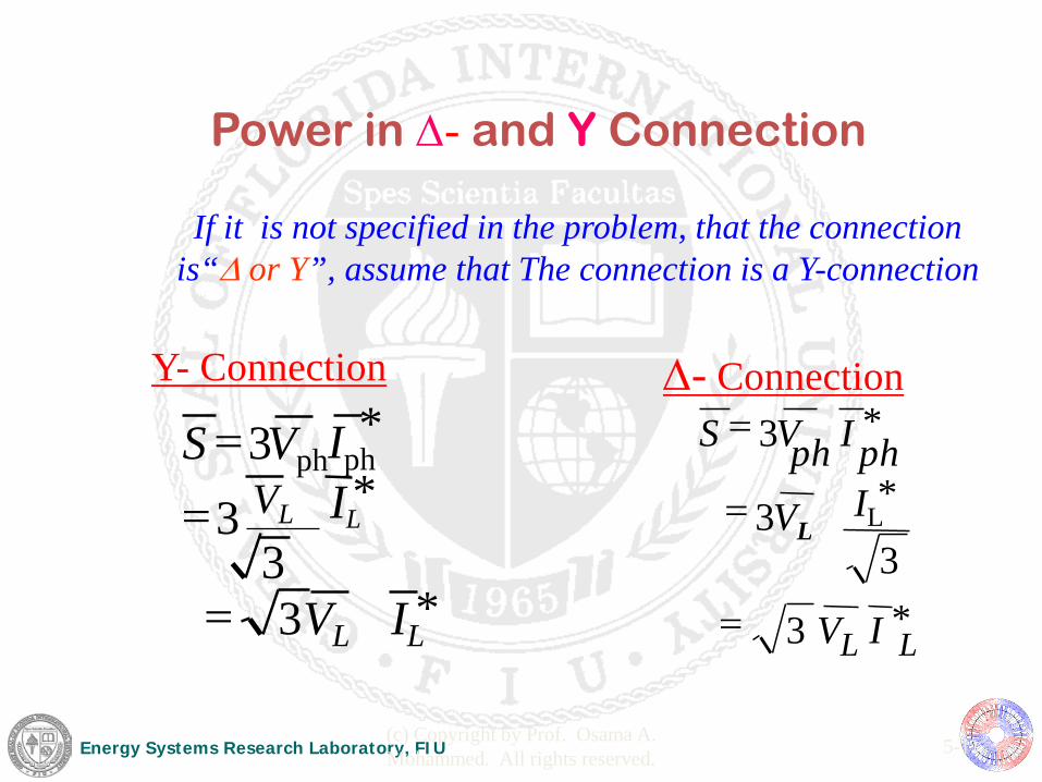
Y- Connection
* 3
* 3
3
* 3
IL VL
IL VL Iph Vph S
=
= =
Power in ∆- and Y Connection
If it is not specified in the problem, that the connection is“∆ or Y”, assume that The connection is a Y-connection
* 3
3 3
* 3
L L
h p h p
I V
IL VL
I V S
=
=
=
*
∆- Connection

Energy Systems Research Laboratory, FIU (c) Copyright by Prof. Osama A. Mohammed. All rights reserved. 5-12
Example
100 kVA 0.8 p.f. lagging 3 phase
Source
13.8 kV
0.4j
0.4j 0.4j
0.3 0.3 0.3

Energy Systems Research Laboratory, FIU (c) Copyright by Prof. Osama A. Mohammed. All rights reserved. 5-13
j0.4 0.3 Load
Load ~
~
Source
Source
One Line Diagram
100 kVA 0.8 p.f. lagging
Energy Systems Research Laboratory, FIU (c) Copyright by Prof. Osama A. Mohammed. All rights reserved. 4-14
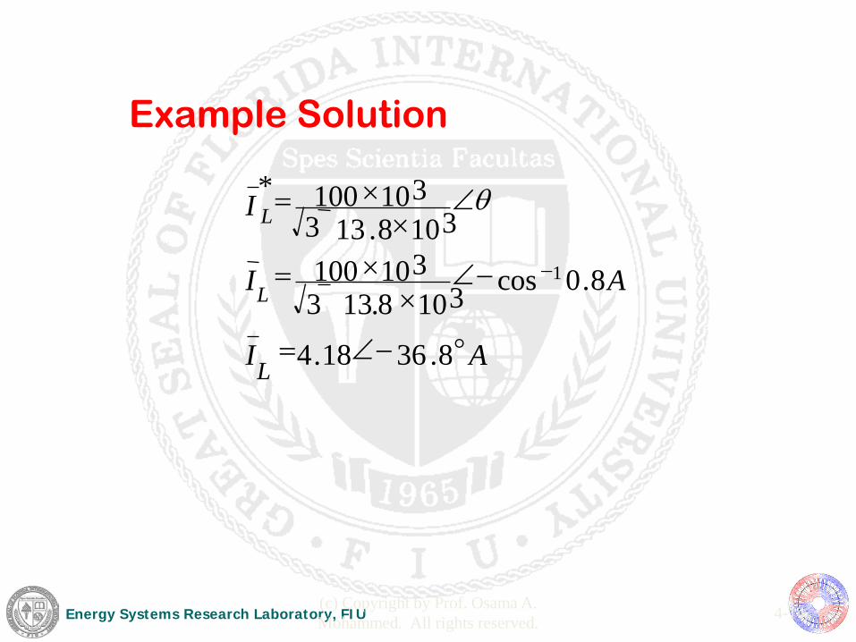
Example Solution
A L I
A I
I
L
L
8 . 36 18 . 4
8 . 0 cos 3 10 8 . 13 3 10 100
3 10 8 . 13 3 10 100 *
1
° − ∠ =
− ∠ ×
× =
∠ ×
× =
−
θ 3
3

Energy Systems Research Laboratory, FIU (c) Copyright by Prof. Osama A. Mohammed. All rights reserved.
1991-1998 4-15
On the other hand, using Y-connection,
IL * = 100 x 103 ∠cos-1 0.8A = 4.18∠36.8° Α
3 13.8 x10³ 3
S = 3 Vp Ip* = 3 Vp IL
*
i.e. IL = 4.18 ∠−36.8° Α

Energy Systems Research Laboratory, FIU (c) Copyright by Prof. Osama A. Mohammed. All rights reserved. 5-16
Example Solution
ph I * ph V S 3 = * V S I
L L 3
= I S L L
* 3 =
° ∠ + ° ∠ = 33 . 16 09 . 2 0 43 . 7967 source V
( ) ( ) ° ∠ ° − ∠ + ° ∠ = 13 . 53 5 . 0 8 . 36 18 . 4 0 43 . 7967 source V
) 3
( ) ( + ° − ∠ + ° ∠ = 4 3 . 0 8 . 36 18 . 4 0 43 . 7967 source j V
( ) ( ) + ° − ∠ + ° ∠ × = 4 3 . 0 8 . 36 18 . 4 0 3
10 8 . 13 source j V
V

Energy Systems Research Laboratory, FIU (c) Copyright by Prof. Osama A. Mohammed. All rights reserved. 5-17
P.U. (per unit)
find Z eq = ? I = ? in p.u. on rated base value
100 kVA @ 0.8p.f. lagging
I
13.8
kV
Based values for “S” and “V”
PER UNIT SYSTEM

Energy Systems Research Laboratory, FIU (c) Copyright by Prof. Osama A. Mohammed. All rights reserved. 5-18
S base = 100 kVA V base = 13.8 kV
S p u S actual S base
. . . = = = 100 100 1 0
V p u V actual V base
. . . . . = = = 13 8
13 8 1 0
the load is operating at 1 p.u.
S V I = × ∗

Energy Systems Research Laboratory, FIU (c) Copyright by Prof. Osama A. Mohammed. All rights reserved. 5-19
I S V
S p u V p u
p u * . .
. . . . = = = = ∠−36.8 °
1 1 0
I actual
=
= ∠ ° ×
×
I p u I base
× . .
. . .
1 0 -36.8 100 10 3
13 8 10 3 x
= 7.246 ∠ -36.8 ° A

Energy Systems Research Laboratory, FIU (c) Copyright by Prof. Osama A. Mohammed. All rights reserved. 5-20
=
old S V
u p Z actual Z 2
. . base new
base old
Z p u new Z
actual Z . . =
Z p u new Z . . = = Z
actual V S
2 S base new
V base new 2
Z p u new Z p u old S
S base new
V base new . . . .
=
2 V2
base old

Energy Systems Research Laboratory, FIU (c) Copyright by Prof. Osama A. Mohammed. All rights reserved. 5-21
Calculate Z at a Different Base
=
new base
new base
base old
base old old u p new u p V
S
S
V Z Z
2
2
. . . .
× = new base
new base
base old
base old base old base new V
S
S
V Z Z
2
2
Z
Z Z pu
base
actual =
Energy Systems Research Laboratory, FIU (c) Copyright by Prof. Osama A. Mohammed. All rights reserved. 5-22
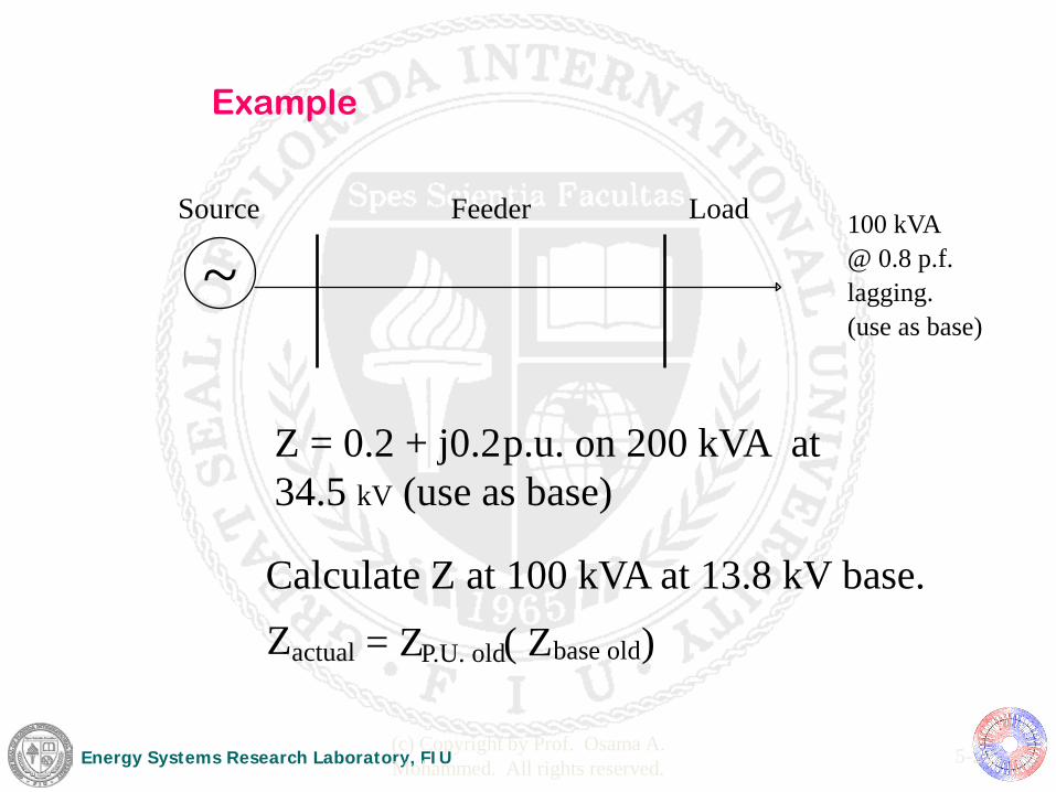
Z = 0.2 + j0.2 p.u. on 200 kVA at 34.5 kV (use as base)
Calculate Z at 100 kVA at 13.8 kV base. Z actual = Z P.U. old ( Z base old )
100 kVA @ 0.8 p.f. lagging. (use as base)
Source Feeder Load
~
Example

Energy Systems Research Laboratory, FIU (c) Copyright by Prof. Osama A. Mohammed. All rights reserved. 5-23
=
Z p u new j . . . . .
. = + ×
×
×
×
0 2 0 2 34 5 10 3
200 10 3
100 10 3
13 8 10 3
Z p u new . . + j . .
0 625 0 625
Z p u new . . = ∠ ° 0 .88 45 p.u.
2
2
Z p.u. new = (0.2+0.2j) 34.5 1 13.8
2
2
Energy Systems Research Laboratory, FIU (c) Copyright by Prof. Osama A. Mohammed. All rights reserved. 5-24
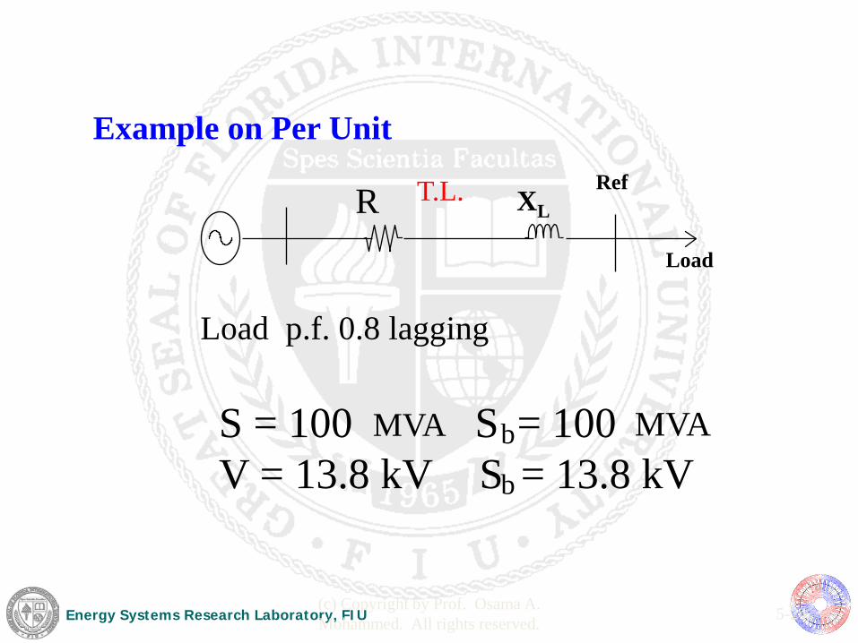
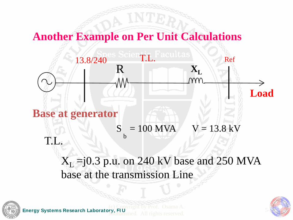
Example on Per Unit
Load p.f. 0.8 lagging
S = 100 MVA S b = 100 MVA V = 13.8 kV S b = 13.8 kV
Load
Ref T.L. R XL

Energy Systems Research Laboratory, FIU (c) Copyright by Prof. Osama A. Mohammed. All rights reserved. 5-25
θ ∠ = S S 0 ∠ = V V
θ ∠ = I I
lagging = “-” leading = “+”
θ ∠ = =
=
V I V
V I V Z
I V Z
2 2
Calculating Impedance Using S and V
Energy Systems Research Laboratory, FIU (c) Copyright by Prof. Osama A. Mohammed. All rights reserved. 5-26
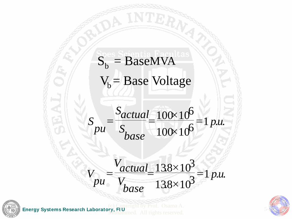
S b = Base MVA
V b = Base Voltage
. . 1 3 10 8 . 13
3 10 8 . 13
. . 1 6 10 100
6 10 100
u p base V
actual V pu V
u p base S
actual S pu S
= × × = =
= × × = =
Energy Systems Research Laboratory, FIU (c) Copyright by Prof. Osama A. Mohammed. All rights reserved. 5-27
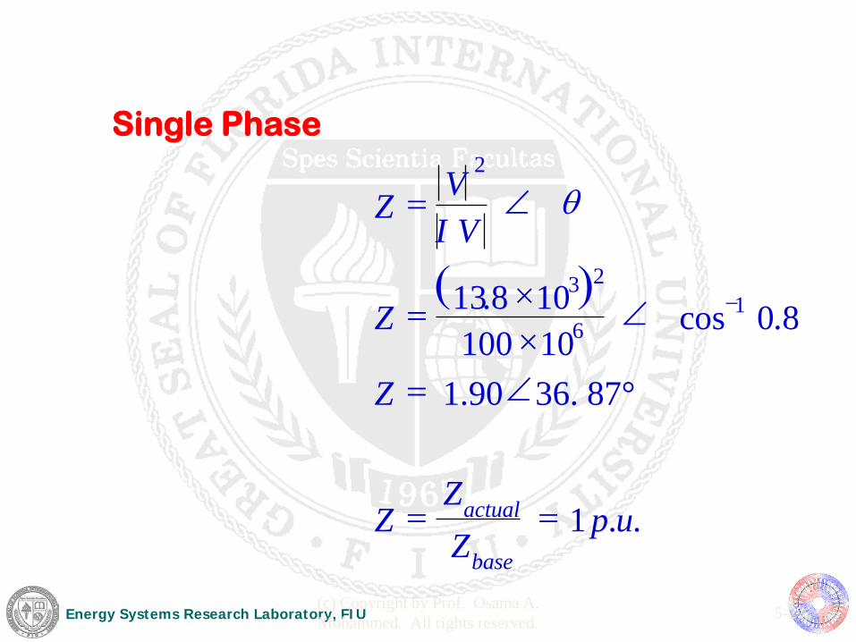
( )
. . 1
36. 87° 1.90
8 . 0 cos 10 100 10 8 . 13 1
6
2 3
2
u p Z Z
Z
Z
Z
V I V
Z
base
actual = =
∠ =
∠ × × =
∠ =
−
θ
Single Phase

Energy Systems Research Laboratory, FIU (c) Copyright by Prof. Osama A. Mohammed. All rights reserved. 5-28
P
Q
cos-1 0.8
1.
cos-1 0.8
2.
V
I
R
X
cos-1 0.8
3.
Power Factor Angle
Power Triangle
Impedance Triangle
Voltage and
Current
Energy Systems Research Laboratory, FIU (c) Copyright by Prof. Osama A. Mohammed. All rights reserved. 5-29
Base at generator S
b = 100 MVA V = 13.8 kV
XL =j0.3 p.u. on 240 kV base and 250 MVA base at the transmission Line
Ref
T.L.
13.8/240
Load
T.L. R XL
Another Example on Per Unit Calculations

Energy Systems Research Laboratory, FIU (c) Copyright by Prof. Osama A. Mohammed. All rights reserved. 5-30
Calculate Z(p.u.) on a new base
=
new base
new base
base old
base old old u p new u p V
S S V
Z Z 2
2
. . . .
× = new base
new base
base old
base old base old base new V
S S
V Z Z 2
2
Z
Z Z pu
base
actual =

Energy Systems Research Laboratory, FIU (c) Copyright by Prof. Osama A. Mohammed. All rights reserved. 5-31
29 pu . 36 90 . 1 12 . 69
100 8 . 13 12 . 69
2 . . = = = = base
actual u p Z
Z Z
( )( ) 4.230
1025010240
6
23
..@ =××
=LTbaseZ
Zactual = Zp.u. Zbase = 0.3 x 230.4 = 69.12 Ohms
Example Solution
Ohms