Lecture 5. Attached Growth Biological Treatment System ...
40
Lecture 5. Attached Growth Biological Treatment System Secondary Treatment Husam Al-Najar The Islamic University of Gaza- Civil Engineering Department Advance wastewater treatment and design (WTEC 9320)
Transcript of Lecture 5. Attached Growth Biological Treatment System ...

Lecture 5. Attached Growth Biological Treatment System
Secondary Treatment
Husam Al-Najar
The Islamic University of Gaza- Civil Engineering Department
Advance wastewater treatment and design (WTEC 9320)

Cross-section of an attached growth biomass film
Wastewater
Oxygen (the natural or forced pump)
filter media
Biomass : viscous, jelly-
like substance containing
bacteria
Organic matter + NH4+

Remove Nutrient
Remove dissolved organic solids
Remove suspended organic solids
Remove suspended solids
Attached Growth is a biological treatment process in which microorganisms
responsible for conversion of organic matter or other constituents in wastewater are
attached to some inert material such as: rocks, sand or specially ceramic or plastic
materials. This process is also called fixed film process.
Trickling filters (biological tower )
Rotating biological contactors ( RBC )
Packed bed reactors
Fluidized bed biofilm reactors

Trickling Filter (TF)- side view
Wastewater
rotating distributor arms
Packing media
Underdrain
rocks, plastic, or
other material
Packing Media- Filter media

Flow Diagram for Trickling Filters
Recycle
Primary
clarifierTrickling
filter
Final
clarifier
Waste
sludge
Final
effluentInfluent
Qr
Q
Importance of recirculation
• recirculation flow dilutes the strength of
raw wastewater & allows untreated
wastewater to be passes through the
filter more than once
• maintain constant wetting rate
• dilute toxic wastes
• increase air flow
• A common range for recirculation
ratio 0.5~3.0

Single stage configuration
PC SC TF
PC SC TF
PC SC TF
a.
b.
c.
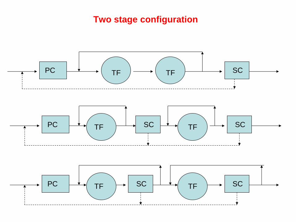
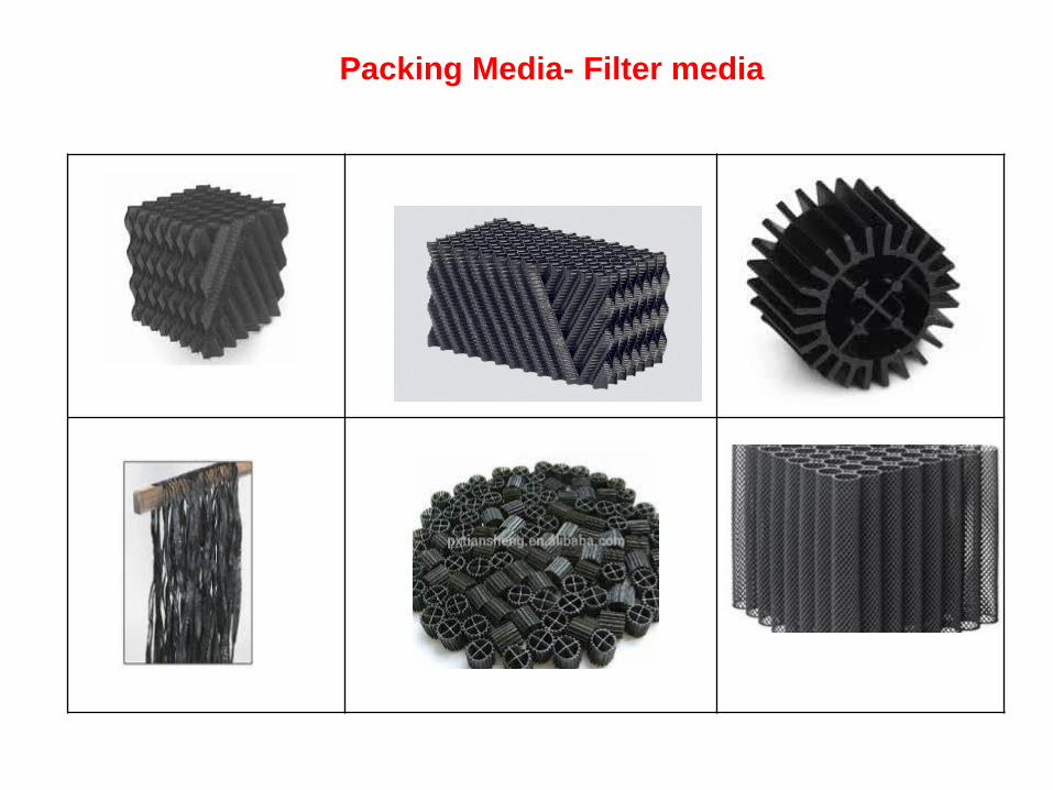
Two stage configuration
PC SC TF
PC SC TF
TF
TF SC
PC SC TF TF SC
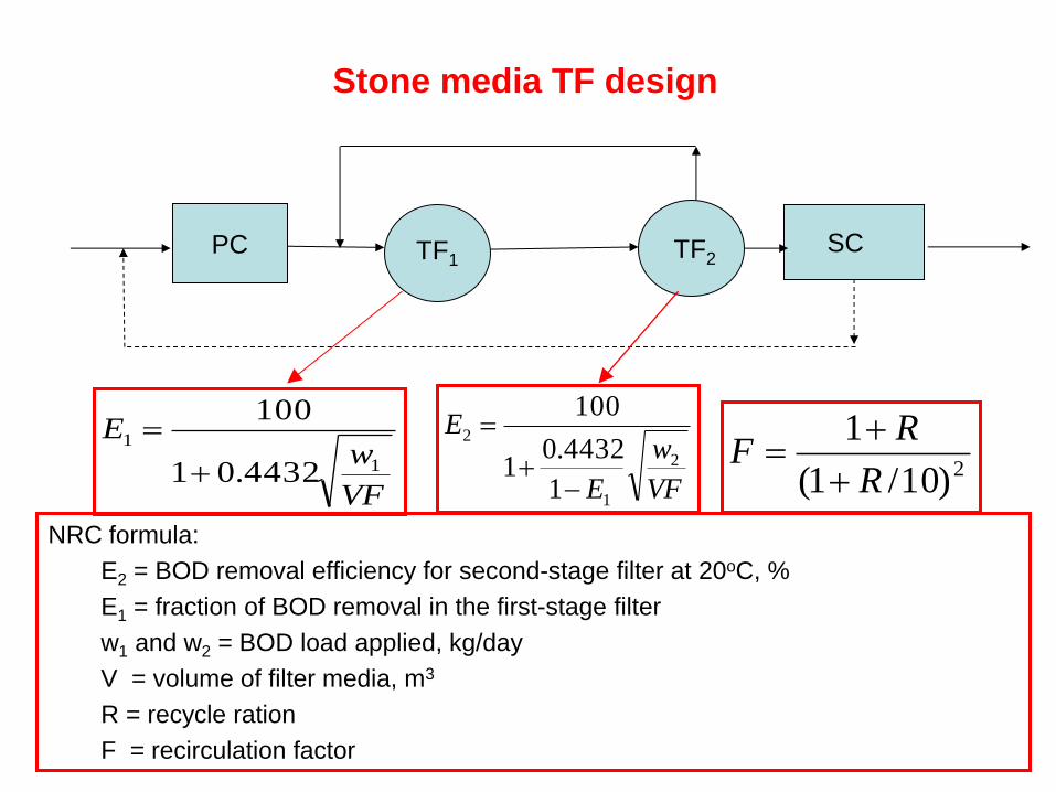
Stone media TF design
PC SC TF2 TF1
VF
wE
1
1
4432.01
100
VF
w
E
E2
1
2
1
4432.01
100
NRC formula:
E2 = BOD removal efficiency for second-stage filter at 20oC, %
E1 = fraction of BOD removal in the first-stage filter
w1 and w2 = BOD load applied, kg/day
V = volume of filter media, m3
R = recycle ration
F = recirculation factor
2)10/1(
1
R
RF

• Organic (BOD) loading rate:
– Expressed as kg/m3/d
– Typically, 0.320-0.640 kg/m3/d for single-stage filters
– Typically, 0.640-0.960 kg/m3/d for two-stage filters
• Hydraulic loading rate:
– m3 wastewater/m2 filter*d
– the rate of total influent flow is applied to the surface of the filter media
– Total influent flow = the raw WW + recirculated flow
– Typically, 9.4 m3/m2/d
– Maximum, 28 m3/m2/d
• The effect of temperature on the BOD removal efficiency
ET = BOD removal efficiency at ToC, %
E20 = BOD removal efficiency at 20oC, %
20
20 )035.1( T
T EE

Example: Calculate the BOD loading, hydraulic loading, BOD
removal efficiency, and effluent BOD concentration of a single-stage
trickling filter based on the following data:
– Design assumptions:
• Influent flow =1530 m3/d
• Recirculation ratio = 0.5
• Primary effluent BOD = 130 mg/L
• Diameter of filter = 18 m
• Depth of media = 2.1 m
• Water temperature =18oC

Solution
(1) BOD loading rate (kg/m3/d)
– BOD load = BOD Conc. x Influent flow
= 130 mg/L x 1530 m3/d =198.9 kg/d
– Volume of filter = surface area of filter x depth
= π (18 m x 18m)/4 X 2.1 m = 533 m3
– BOD loading rate = BOD load / volume of filter
=0.37 kg/m3/d
(2) Hydraulic loading rate (m3/m2/d)
– Total flow to the media = influent + recirculation flow
= 1530 m3/d + (1530 m3/d x 0.5)
– Surface area of filter = π (18 m x 18m)/4 = 254 m3
– Hydraulic loading rate = Total flow to the media / area of filter
= 9.04 m3/m2/d

(3) Effluent BOD (mg/L)
– BOD removal efficiency for first-stage filter at 20oC, %
%7.75)035.1(2.81)035.1( 22018
2018 EE
VF
wE
1
1
4432.01
100
36.1)10/5.01(
5.01
)10/1(
122
R
RF
%2.81
36.1
37.04432.01
100
4432.01
100
1
1
VF
wE
100
)7.75100(/130)/(
LmgLmgBODEffluent = 31.6
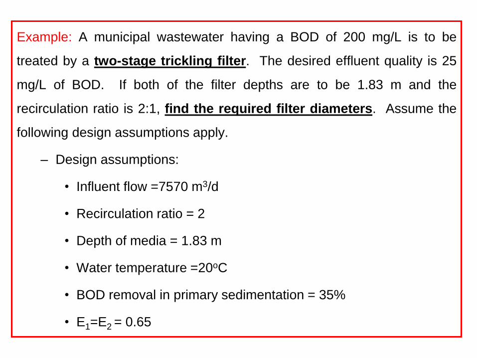
Example: A municipal wastewater having a BOD of 200 mg/L is to be
treated by a two-stage trickling filter. The desired effluent quality is 25
mg/L of BOD. If both of the filter depths are to be 1.83 m and the
recirculation ratio is 2:1, find the required filter diameters. Assume the
following design assumptions apply.
– Design assumptions:
• Influent flow =7570 m3/d
• Recirculation ratio = 2
• Depth of media = 1.83 m
• Water temperature =20oC
• BOD removal in primary sedimentation = 35%
• E1=E2 = 0.65

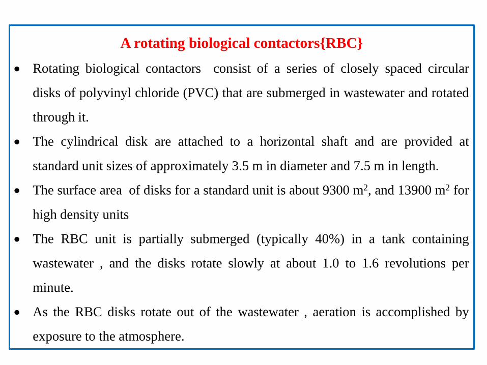
A rotating biological contactors{RBC}
Rotating biological contactors consist of a series of closely spaced circular
disks of polyvinyl chloride (PVC) that are submerged in wastewater and rotated
through it.
The cylindrical disk are attached to a horizontal shaft and are provided at
standard unit sizes of approximately 3.5 m in diameter and 7.5 m in length.
The surface area of disks for a standard unit is about 9300 m2, and 13900 m2 for
high density units
The RBC unit is partially submerged (typically 40%) in a tank containing
wastewater , and the disks rotate slowly at about 1.0 to 1.6 revolutions per
minute.
As the RBC disks rotate out of the wastewater , aeration is accomplished by
exposure to the atmosphere.
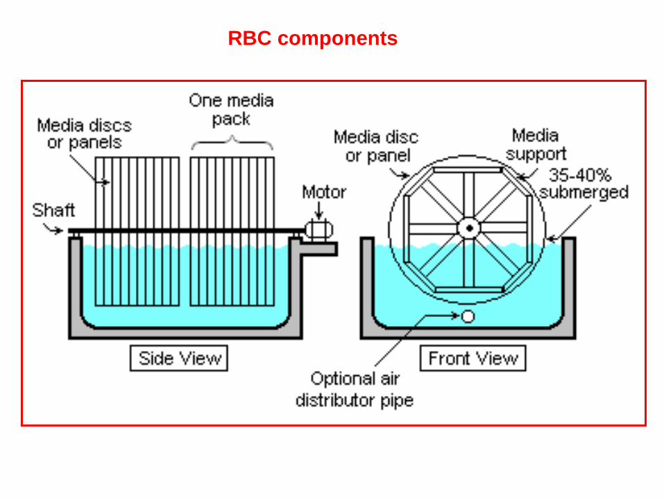
RBC components


RBC process design considerations:-
The following are the main design parameters needed to design the RBC
System :-
• Staging of the RBC units
• Organic loading rate
• Hydraulic loading rate
RBC staging:-
• The RBC process application typically consists of a number of units operated in
series.
• For this purpose, RPC is divided into stages . Number of stages depends on the
treatment goals . For BOD removal “ 2 ” to “ 4” stages are needed and “ 6” or
more stages for nitrification.

1st Stage 2nd Stage 3rd Stage 4th Stage
To
secondary
clarifier Influent
RBC unit
NOTE : the number of shafts in each stage depends on the treatment efficiency required.
The separation between stages is accomplished by using baffles in a single tank or by
a series of separate tanks.
As the wastewater flow through the system , each subsequent stage receives an
influent with a lower organic matter concentration than the previous stage.
The RBC units may be arranged parallel or normal to the direction of wastewater flow.

dm
leso
2
lub
dm
BODg
2
5 )(
dm
gN
2
dm
BOD s
2
5 )(
Organic loading rate:
The organic loading rate for RBC in typically in the range 4-10 g (BOD)
for BOD removal only.
If both BOD removal and nitrification, the range is 2.5- 4
The maximum 1st stage organic loading is 12-15
Nitrifying bacteria can not develop in RBC until (BOD5) drops to less than 15 mg/ L.
The maximum nitrogen surface removal rate that has been observed to be about 1.5 .

Hydraulic loading rate:
The typical hydraulic loading rate of 0.08-0.16 23 / mm for 5BOD removal
and 0.03-0.08 23 / mm for both 5BOD removal and nitrification.
The hydraulic detention time ( ) is 0.7-1.5 hrs for 5BOD removal and
1.5-4 hrs for both 5BOD removal and nitrification.
The volume of RBC tank has been optimized at 0.004923 / mm for one
shaft of 93002m .
A tank volume of 45 3m is needed. Based on this volume and a hydraulic
loading rate of 0.08 dmm ./ 23 the detention time is 1.44 hrs. Atypical side
wall depth is 1.5m to achieve 40% submergence.

Bar
screen
Grit
removal
Primary
Sedimentation
RBC
units Final
clarifier
effluent
1st stage
2nd
stage
RBC configuration
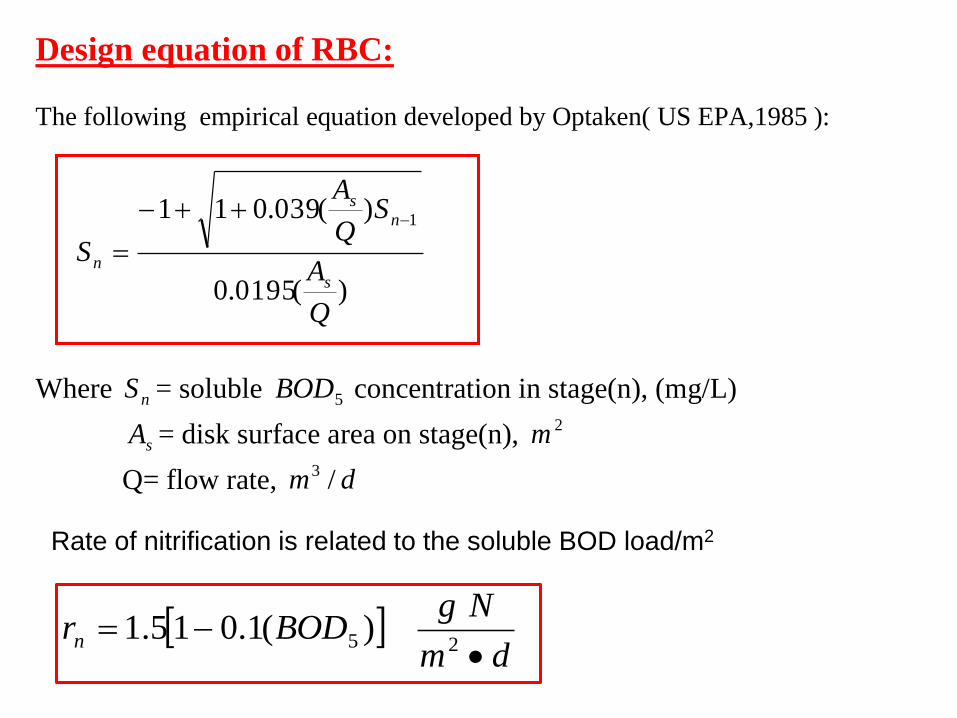
Design equation of RBC: The following empirical equation developed by Optaken( US EPA,1985 ):
)(0195.0
)(039.011 1
Q
A
SQ
A
Ss
ns
n
Where nS = soluble 5BOD concentration in stage(n), (mg/L)
sA = disk surface area on stage(n), 2m
Q= flow rate, dm /3
Rate of nitrification is related to the soluble BOD load/m2
dm
NgBODrn
25 )(1.015.1

RBC design Example: Design a rotating biological contractor to treat an
influent soluble 5BOD of 90 mg 5BOD /L. The flow(Q)= 4000 3m /d
Solution:
Assume 1st stage ( 5BOD ) organic loading= 15g/ 2m .d
5BOD (loading)= ( 5BOD ) concentration inQ
=d
g
mg
g
m
L
d
m
L
mg000,360
10
10400090
33
33
Disk area= 2
2
24000
.15
000,360m
dmg
dg
(first area stage)
Use shaft
m2
9300 so number of shafts needed for the first stage:
N= 6.29300
240002
2
shaftm
m say 3 shafts

Calculate S1, the BOD concentration after the first stage:
Sn=)(0195.0
)(039.011 1
QAs
SQ
Asn
For the first stage n=1, Sn=S1, Sn-1 = S0
S0 = 90 mg/L, AS = dm
Qm3
2 4000,2790093003
md
dm
m
Q
AS 98.6/4000
279003
2
S1=L
mg
L
mg1475.29
98.60195.0
9098.6039.011
So we need one more stage.

Add another stage and calculate S2:
Assume two shafts in the second stage:
AS=22 1860093002 mm
d
m
Q
AS 65.44000
18600
Sn=S2, Sn-1=S2-1=S1=29.75mg/L
S2=L
mg
L
mg1486.16
65.40195.0
75.2965.4039.011
So we need one more stage.
Add another stage and calculate S3:
Assume one shaft in the third stage:
AS=22 930093001 mm
m
d
d
m
m
Q
AS 33.2
4000
93003
2

Follow Example RBC design example:
Sn=S3,Sn-1=S3-1=S2=16.86mg/L
S3=L
mg
L
mg1413
33.20195.0
86.1633.2039.011
OK
So three stages are enough.
Check for the hydraulic loading:
HLR=shafteachofAreashaftsofnumbertotal
Q
Nshafts=3+2+1= 6 shafts
HLR=dm
md
m
2
3
3
072.093006
4000
, typical range(0.08-0.16), which is a
little bit lower than the range.

Is nitrification possible in any of the three stages?:
*Nitrification is only possible when soluble 5BOD loading is less than
10g dm
BOD
2
1st stage =
dm
gBOD
m
g
d
m
2
5
3
3
9.1293003
1904000 <10(no
nitrification)
2nd
stage = dm
gBOD
m
g
d
m
2
5
3
3
4.693002
175.294000
(nitrification occurs)
3rd
stage = dm
gBOD
m
g
d
m
2
5
3
3
25.793001
186.164000
(nitrification occurs)

*Rate of nitrification is related to the soluble 5BOD loading by the
following equation:
dm
NgBODrn
25 )(1.015.1
* So for 2nd
stage→ dm
Ngrn
254.04.61.015.1
* And for 3rd
stage→ dm
Ngrn
2413.025.71.015.1
*If the ammonia concentration in the influent to the 2nd
stage is 30
mgN/L, find the effluent ammonia concentration.
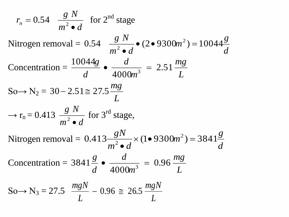
dm
Ngrn
254.0 for 2
nd stage
Nitrogen removal = d
gm
dm
Ng10044)93002(54.0 2
2
Concentration = L
mg
m
d
d
g51.2
4000
100443
So→ N2 = L
mg5.2751.230
→ rn = 0.413 dm
Ng
2 for 3
rd stage,
Nitrogen removal = d
gm
dm
gN3841)93001(413.0 2
2
Concentration = L
mg
m
d
d
g96.0
40003841
3
So→ N3 = 27.5 L
mgN
L
mgN5.2696.0

If complete nitrification is needed a separate nitrification stage should be added
after these stages.
Qin = 4000 m3/d
So = 90 mg/L
N = 30 mgN/L
Shaft 1
Shaft 2
Shaft 3
Shaft 1
Shaft 2
Shaft 1
Se = 13 mg BOD5 /L
Ne = 26 .50 mg N/L
A = 9300m2
A = 9300m2
Proposed design
Note: each shaft has a tank volume of 45m3.

Appendix

Plastic media TF design
Schulze formula
• The liquid contact time (t) of applied wastewater
Where:
t = liquid contact time, min
D= depth of media (m)
q = hydraulic loading, (m3/m2/h)
C, n = constants related to specific surface & configuration of media
nq
CDt

• hydraulic loading (q)
Where:
Q= influent flow rate L/min
A=filter cross section area m2
A

Schulze formula for Plastic Media Trickling Filter Design
Where:
Se= BOD concentration of settled filter effluent, mg/L
So= influent BOD concentration to the filter, mg/L
k=wastewater treatability and packing coefficient, (L/s)0.5/m2
D=packing depth, m
q= hydraulic application rate of primary effluent, excluding recirculation, L/m2*s
n=constant characteristic of packing used (assumed to be 0.5).
)/( nqkD
o
e eS
S
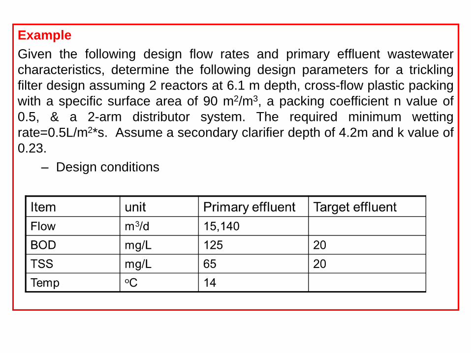
Example
Given the following design flow rates and primary effluent wastewater
characteristics, determine the following design parameters for a trickling
filter design assuming 2 reactors at 6.1 m depth, cross-flow plastic packing
with a specific surface area of 90 m2/m3, a packing coefficient n value of
0.5, & a 2-arm distributor system. The required minimum wetting
rate=0.5L/m2*s. Assume a secondary clarifier depth of 4.2m and k value of
0.23.
– Design conditions
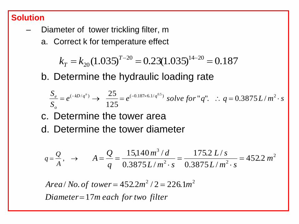
Solution
– Diameter of tower trickling filter, m
a. Correct k for temperature effect
187.0)035.1(23.0)035.1( 201420
20 T
T kk
b. Determine the hydraulic loading rate
c. Determine the tower area
d. Determine the tower diameter
)/( nqkD
o
e eS
S
filtertwoforeachmDiameter
mmtowerofNoArea
17
1.2262/2.452./ 22
,A
smLqqforsolvee q 2)/1.6187.0( /3875.0"."125
25 5.0
2
22
3
2.452/3875.0
/2.175
/3875.0
/140,15m
smL
sL
smL
dm
q
QA