Lecture 4: Overview of Refinery...
17
NPTEL – Chemical – Chemical Technology II Joint initiative of IITs and IISc – Funded by MHRD Page 12 of 83 Lecture 4: Overview of Refinery Processes 4.1 Introduction In this lecture, a brief overview of various refinery processes is presented along with a simple sketch of the process block diagram of a modern refinery. The sketch of the modern refinery indicates the underlying complexity and the sketch is required to have a good understanding of the primary processing operations in various sub-processes and units. 4.2 Refinery flow sheet We now present a typical refinery flowsheet for the refining of middle eastern crude oil. There are about 22 units in the flowsheet which themselves are complex enough to be regarded as process flow sheets. Further, all streams are numbered to summarize their significance in various processing steps encountered in various units. However, for the convenience of our understanding, we present them as units or blocks which enable either distillation in sequence or reactive transformation followed by distillation sequences to achieve the desired products. The 22 units presented in the refinery process diagram are categorized as - Crude distillation unit (CDU) - Vacuum distillation unit (VDU) - Thermal cracker - Hydrotreaters - Fluidized catalytic cracker - Separators - Naphtha splitter - Reformer - Alkylation and isomerisation - Gas treating - Blending pools - Stream splitters
Transcript of Lecture 4: Overview of Refinery...

NPTEL – Chemical – Chemical Technology II
Joint initiative of IITs and IISc – Funded by MHRD Page 12 of 83
Lecture 4: Overview of Refinery Processes
4.1 Introduction
In this lecture, a brief overview of various refinery processes is presented
along with a simple sketch of the process block diagram of a modern
refinery. The sketch of the modern refinery indicates the underlying
complexity and the sketch is required to have a good understanding of the
primary processing operations in various sub-processes and units.
4.2 Refinery flow sheet
We now present a typical refinery flowsheet for the refining of middle
eastern crude oil. There are about 22 units in the flowsheet which
themselves are complex enough to be regarded as process flow sheets.
Further, all streams are numbered to summarize their significance in various
processing steps encountered in various units. However, for the
convenience of our understanding, we present them as units or blocks which
enable either distillation in sequence or reactive transformation followed by
distillation sequences to achieve the desired products.
The 22 units presented in the refinery process diagram are categorized as
- Crude distillation unit (CDU)
- Vacuum distillation unit (VDU)
- Thermal cracker
- Hydrotreaters
- Fluidized catalytic cracker
- Separators
- Naphtha splitter
- Reformer
- Alkylation and isomerisation
- Gas treating
- Blending pools
- Stream splitters

NPTEL – Chemical – Chemical Technology II
Joint initiative of IITs and IISc – Funded by MHRD Page 13 of 83
A brief account of the above process units along with their functional role is
presented next with simple conceptual block diagrams representing the
flows in and out of each unit.
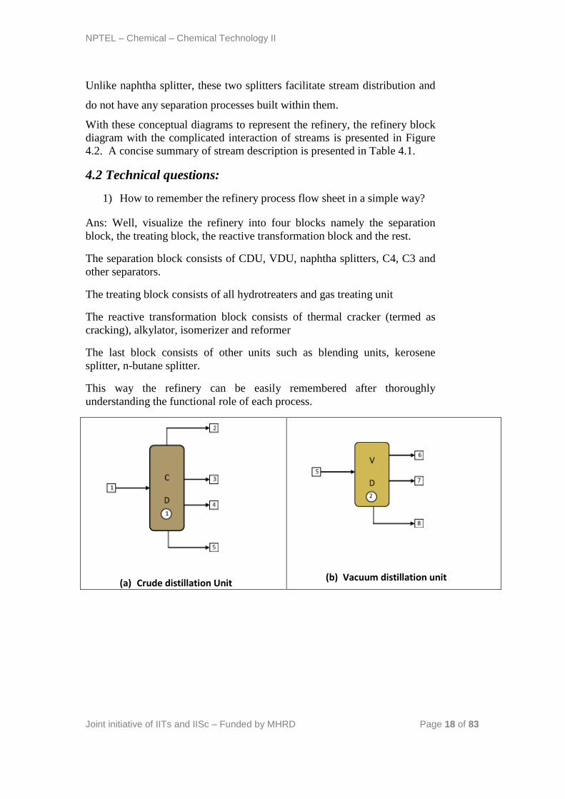
a) Crude distillation unit
The unit comprising of an atmospheric distillation column, side strippers,
heat exchanger network, feed de-salter and furnace as main process
technologies enables the separation of the crude into its various products.
Usually, five products are generated from the CDU namely gas + naphtha,
kerosene, light gas oil, heavy gas oil and atmospheric residue (Figure 4.1a).
In some refinery configurations, terminologies such as gasoline, jet fuel and
diesel are used to represent the CDU products which are usually fractions
emanating as portions of naphtha, kerosene and gas oil. Amongst the crude
distillation products, naphtha, kerosene have higher product values than gas
oil and residue. On the other hand, modern refineries tend to produce
lighter components from the heavy products. Therefore, reactive
transformations (chemical processes) are inevitable to convert the
heavy intermediate refinery streams into lighter streams.
Operating Conditions : The temperature at the entrance of the furnace
where the crude enters is 200 – 280oC. It is then further heated to about
330 – 370oC inside the furnace. The pressure maintained is about 1
barg.
b) Vacuum distillation unit (VDU)
The atmospheric residue when processed at lower pressures does not allow
decomposition of the atmospheric residue and therefore yields LVGO,
HVGO and vacuum residue (Figure 4.1b). The LVGO and HVGO are
eventually subjected to cracking to yield even lighter products. The VDU
consists of a main vacuum distillation column supported with side strippers
to produce the desired products. Therefore, VDU is also a physical process
to obtain the desired products.
Operating Conditions : The pressure maintained is about 25 – 40 mm Hg.
The temperature is kept at around 380 – 420oC.

NPTEL – Chemical – Chemical Technology II
Joint initiative of IITs and IISc – Funded by MHRD Page 14 of 83
c) Thermal cracker
Thermal cracker involves a chemical cracking process followed by the
separation using physical principles (boiling point differences) to yield the
desired products. Thermal cracking yields naphtha + gas, gasoil and thermal
cracked residue (Figure 4.1c). In some petroleum refinery configurations,
thermal cracking process is replaced with delayed coking process to yield
coke as one of the petroleum refinery products.
Operating Conditions : The temperature should be kept at around 450
– 500oC for the larger hydrocarbons to become unstable and break
spontaneously. A 2-3 bar pressure must be maintained.
d) Hydrotreaters
For many refinery crudes such as Arabic and Kuwait crudes, sulfur content
in the crude is significantly high. Therefore, the products produced from
CDU and VDU consist of significant amount of sulfur. Henceforth, for
different products generated from CDU and VDU, sulfur removal is
accomplished to remove sulfur as H2S using Hydrogen. The H2 required for
the hydrotreaters is obtained from the reformer unit where heavy naphtha is
subjected to reforming to yield high octane number reforme product and
reformer H2 gas. In due course of process, H2S is produced. Therefore, in
industry, to accomplish sulfur removal from various CDU and VDU
products, various hydrotreaters are used. In due course of hydrotreating in
some hydrotreaters products lighter than the feed are produced. For
instance, in the LVGO/HVGO hydrotreater, desulfurization of LVGO &
HVGO (diesel) occurs in two blocked operations and desulfurized naphtha
fraction is produced along with the desulfurized gas oil main product
(Figure 4.1 f). Similarly, for LGO hydrotreating case, along with diesel
main product, naphtha and gas to C5 fraction are obtained as other products
(Figure 4.1e). Only for kerosene hydrotreater, no lighter product is
produced in the hydrotreating operation. It is further interesting to note that
naphtha hydrotreater is fed with both light and heavy naphtha as feed which
is desulfurized with the reformer off gas. In this process, light ends from
NPTEL – Chemical – Chemical Technology II
Joint initiative of IITs and IISc – Funded by MHRD Page 15 of 83
the reformer gas are stripped to enhance the purity of hydrogen to about 92
% (Figure 4.1d). Conceptually, hydrotreating is regarded as a combination
of chemical and physical processes.
Operating Conditions: The operating conditions of a hydrotreater
varies with the type of feed.
For Naphtha feed, the temperature may be kept at around 280-425oC
and the pressure be maintained at 200 – 800 psig.
e) Fluidized catalytic cracker
The unit is one of the most important units of the modern refinery. The unit
enables the successful transformation of desulfurized HVGO to lighter
products such as unsaturated light ends, light cracked naphtha, heavy
cracked naphtha, cycle oil and slurry (Figure 4.1i). Thereby, the unit is
useful to generate more lighter products from a heavier lower value
intermediate product stream. Conceptually, the unit can be regarded as a
combination of chemical and physical processes.
Operating Conditions: The temperature should be maintained at 34oC
with pressure ranging from 75 kPa to 180 kPa. Moreover, the process is
to be carried out in a relatively wet environment.
f) Separators
The gas fractions from various units need consolidated separation and
require stage wise separation of the gas fraction. For instance, C4 separator
separates the desulfurized naphtha from all saturated light ends greater than
or equal to C4s in composition (Figure 4.1g). On the other hand, C3
separator separates butanes (both iso and nbutanes) from the gas fraction
(Figure 4.1j). The butanes thus produced are of necessity in isomerization
reactions, LPG and gasoline product generation. Similarly, the C2 separator
separates the saturated C3 fraction that is required for LPG product
generation (Figure 4.1k) and generates the fuel gas + H2S product as well.
All these units are conceptually regarded as physical processes.
Operating Conditions: Most oil and gas separators operate in the
pressure range of 20 – 1500 psi.

NPTEL – Chemical – Chemical Technology II
Joint initiative of IITs and IISc – Funded by MHRD Page 16 of 83
g) Naphtha splitter
The naphtha splitter unit consisting of a series of distillation columns
enables the successful separation of light naphtha and heavy naphtha from
the consolidated naphtha stream obtained from several sub-units of the
refinery complex (Figure 4.1n). The naphtha splitter is regarded as a
physical process for modeling purposes.
Operating Conditions: The pressure is to be maintained between 1
kg/cm2 to 4.5 kg/cm
2. The operating temperature range should be 167 –
250oC
h) Reformer
As shown in Figure 4.1o, Heavy naphtha which does not have high octane
number is subjected to reforming in the reformer unit to obtain reformate
product (with high octane number), light ends and reformer gas (hydrogen).
Thereby, the unit produces high octane number product that is essential to
produce premium grade gasoline as one of the major refinery products. A
reformer is regarded as a combination of chemical and physical processes.
Operating Conditions : The initial liquid feed should be pumped at a
reaction pressure of 5 – 45 atm, and the preheated feed mixture should
be heated to a reaction temperature of 495 – 520oC.
i) Alkylation & Isomerization
The unsaturated light ends generated from the FCC process are stabilized by
alkylation process using iC4 generated from the C4 separator. The process
yields alkylate product which has higher octane number than the feed
streams (Figure 4.1r). As isobutane generated from the separator is enough
to meet the demand in the alkylation unit, isomerization reaction is carried
out in the isomerization unit (Figure 4.1q) to yield the desired make up iC4.
j) Gas treating
The otherwise not useful fuel gas and H2S stream generated from the C2
separator has significant amount of sulfur. In the gas treating process, H2S
is successfully transformed into sulfur along with the generation of fuel gas
(Figure 4.1m). Eventually, in many refineries, some fuel gas is used for

NPTEL – Chemical – Chemical Technology II
Joint initiative of IITs and IISc – Funded by MHRD Page 17 of 83
furnace applications within the refinery along with fuel oil (another refinery
product generated from the fuel oil pool) in the furnace associated to the
CDU.
Operating Conditions: Gas treaters may operate at temperatures
ranging from 150 psig (low pressure units) to 3000 psig (high pressure
units).
k) Blending pools
All refineries need to meet tight product specifications in the form of ASTM
temperatures, viscosities, octane numbers, flash point and pour point. To
achieve desired products with minimum specifications of these important
parameters, blending is carried out. There are four blending pools in a
typical refinery. While the LPG pool allows blending of saturated C3s and
C4s to generate C3 LPG and C4 LPG, which do not allow much blending of
the feed streams with one another (Figure 4.1t). The most important
blending pool in the refinery complex is the gasoline pool where in both
premium and regular gasoline products are prepared by blending appropriate
amounts of n-butane, reformate, light naphtha, alkylate and light cracked
naphtha (Figure 4.1u). These two products are by far the most profit
making products of the modern refinery and henceforth emphasis is there to
maximize their total products while meeting the product specifications. The
gasoil pool (Figure 4.1v) produces automotive diesel and heating oil from
kerosene (from CDU), LGO, LVGO and slurry. In the fuel oil pool (Figure
4.1w), haring diesel, heavy fuel oil and bunker oil are produced from
LVGO, slurry and cracked residue.
l) Stream splitters
To facilitate stream splitting, various stream splitters are used in the refinery
configuration. A kerosene splitter is used to split kerosene between the
kerosene product and the stream that is sent to the gas oil pool (Figure
4.1h). Similarly, butane splitter splits the n-butane stream into butanes
entering LPG pool, gasoline pool and isomerization unit (Figure 4.1p).
NPTEL – Chemical – Chemical Technology II
Joint initiative of IITs and IISc – Funded by MHRD Page 18 of 83
Unlike naphtha splitter, these two splitters facilitate stream distribution and
do not have any separation processes built within them.
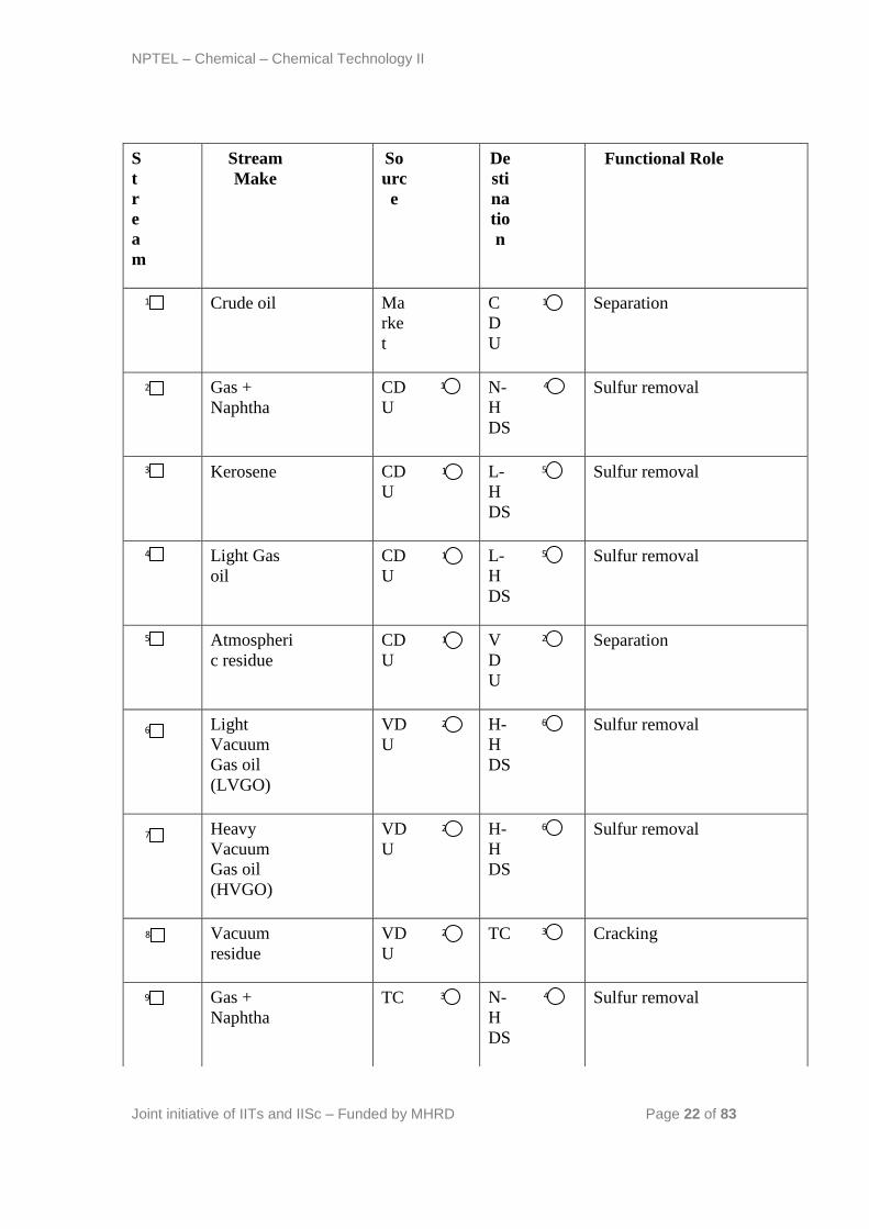
With these conceptual diagrams to represent the refinery, the refinery block
diagram with the complicated interaction of streams is presented in Figure
4.2. A concise summary of stream description is presented in Table 4.1.
4.2 Technical questions:
1) How to remember the refinery process flow sheet in a simple way?
Ans: Well, visualize the refinery into four blocks namely the separation
block, the treating block, the reactive transformation block and the rest.
The separation block consists of CDU, VDU, naphtha splitters, C4, C3 and
other separators.
The treating block consists of all hydrotreaters and gas treating unit
The reactive transformation block consists of thermal cracker (termed as
cracking), alkylator, isomerizer and reformer
The last block consists of other units such as blending units, kerosene
splitter, n-butane splitter.
This way the refinery can be easily remembered after thoroughly
understanding the functional role of each process.
(a) Crude distillation Unit
(b) Vacuum distillation unit

NPTEL – Chemical – Chemical Technology II
Joint initiative of IITs and IISc – Funded by MHRD Page 19 of 83
(c)Thermal Cracker
(d) Naphtha HDS
(e) LGO Hydrotreater
(f) HGO Hydrotreater
(g) C4 Separator
(i) FCC Unit
(h) Kerosene Splitter
(j) C3 Separator

NPTEL – Chemical – Chemical Technology II
Joint initiative of IITs and IISc – Funded by MHRD Page 20 of 83
(k) C2 Separator Unit
(m) Gas treating Unit
(n) Naphtha Splitter
(o) Catalytic Reformer
(p) n-Butane Splitter
(q) Isomerization Unit
(r)Alkylation Unit
(s) LVGO Splitter
(t) LPG Pool Unit
(u) Gasoline Pool

NPTEL – Chemical – Chemical Technology II
Joint initiative of IITs and IISc – Funded by MHRD Page 21 of 83
(v) Gasoil Pool
(w) Fuel Oil Pool
Figure 4.1: Summary of prominent sub-process units in a typical petroleum refinery complex.
NPTEL – Chemical – Chemical Technology II
Joint initiative of IITs and IISc – Funded by MHRD Page 22 of 83
S
t
r
e
a
m
Stream
Make
So
urc
e
De
sti
na
tio
n
Functional Role
Crude oil Ma
rke
t
C
D
U
Separation
Gas +
Naphtha
CD
U
N-
H
DS
Sulfur removal
Kerosene CD
U
L-
H
DS
Sulfur removal
Light Gas
oil
CD
U
L-
H
DS
Sulfur removal
Atmospheri
c residue
CD
U
V
D
U
Separation
Light
Vacuum
Gas oil
(LVGO)
VD
U
H-
H
DS
Sulfur removal
Heavy
Vacuum
Gas oil
(HVGO)
VD
U
H-
H
DS
Sulfur removal
Vacuum
residue
VD
U
TC Cracking
Gas +
Naphtha
TC N-
H
DS
Sulfur removal
1 1
2 1 4
3 1 5
4 1 5
5 1 2
6 2 6
7 2 6
8 2 3
9 3 4

NPTEL – Chemical – Chemical Technology II
Joint initiative of IITs and IISc – Funded by MHRD Page 23 of 83
Cracked
Gas oil
TC L-
H
DS
Sulfur removal
Cracked
residue
TC FO
P
Product Blending
Hydrogen N-
HD
S
L-
H
DS
H-
H
DS
Hydrodesulfurizatio
n of intermediate
products
Desulfurize
d Gas +
Naphtha
N-
HD
S
SE
P-
C4
Separation of gas
(< C4) and Naphtha
(LN + HN)
Desulfurize
d Gas +
Naphtha
L-
HD
S
N-
H
DS
Naphtha
stabilization (to
saturate
unsaturates)
Desulfurize
d Kerosene
L-
HD
S
K-
SP
Splitting Kerosene
for blending pool
and product
Desulfurize
d LGO
L-
HD
S
G
OP
Togenerate Auto
diesel and heating
oil products
Desulfurize
d Gas +
Naphtha
H-
HD
S
N-
H
DS
Naphtha
stabilization (to
saturate
unsaturates)
Desulfurize
d LVGO
H-
HD
S
LV
-
SP
To by-pass the
stream
Desulfurize H- FC To catalytically
10
3 5
11
3 22
12
4 5
6
13
4 7
14
5 4
15
8 5
16
21
5
17
6 4
18
18
6
19
9 6

NPTEL – Chemical – Chemical Technology II
Joint initiative of IITs and IISc – Funded by MHRD Page 24 of 83
d HVGO HD
S
C
crack and produce
lighter products
Saturated
light ends
SE
P-
C4
SE
P-
C3
To separate C3s
from C4 fraction
Desulfurize
d LN+HN
SE
P-
C4
NS To split Light
Naphtha (LN) from
Heavy Naphtha
(HN)
Desulfurize
d Kerosene
product
K-
SP
Sto
rag
e
tan
k
Storage
Desulfurize
d Kerosene
K-
SP
G
OP
To blend and
produce auto diesel
and heating oil
Gaseous
FCC
product
FC
C
GT
Sulfur recovery and
fuel gas production
Unsaturated
Light Ends
FC
C
AL
K
Conversion of C3-4
to alkylates
Light
cracked
naphtha
FC
C
GP
Togenerate
Premium and
regular gasoline
Heavy
cracked
naphtha
FC
C
GP
Togenerate
Premium and
regular gasoline
Cycle oil FC
C
G
OP
Togenerate Auto
diesel and heating
oil products
20
7 10
21
7 13
22
8
23
8 21
24
12
9
25
17
9
26
9 20
27
9 20
28
9 21

NPTEL – Chemical – Chemical Technology II
Joint initiative of IITs and IISc – Funded by MHRD Page 25 of 83
Slurry FC
C
FO
P
Togenerate haring
diesel, heavy fuel
oil and bunker oil
Saturated
light ends (<
C3s)
SE
P-
C3
SE
P-
C2
To separate C3s
from the stream
C4s (normal
and
Isobutane
mixture)
SE
P-
C3
B-
SP
To by-pass the
stream
Fuel gas +
H2S
SE
P-
C2
GT
To recover sulfur
and produce Fuel
gas
C3s SE
P-
C2
LP
GP
To recover sulfur
and produce Fuel
gas
Fuel gas GT
Fu
el
gas
sto
rag
e
tan
k
Storage
Sulfur GT Sul
fur
sto
rag
e
tan
k
Storage
Desulfurize
d LN
NS GP To prepare
Premium and
Regular gasoline
products
29
9 22
30
11
10
31
15
10
32
12
11
33
19
11
34
12
35
12
36
20
13

NPTEL – Chemical – Chemical Technology II
Joint initiative of IITs and IISc – Funded by MHRD Page 26 of 83
Desulfurize
d HN
NS CR To crack heavy
naphtha into lighter
products
Reformer
off-gas
CR N-
H
DS
H2 purication by
loss of Light Ends
in N-HDS process
Cracked
Light ends
CR SE
P-
C3
To separate < C3’s
from Butanes
Reformate CR GP To prepare
premium and
regular gasoline
products
Normal
Butane
B-
SP
LP
GP
To produce C3
LPG and C4 LPG
products
Normal
Butane
B-
SP
GP To produce
premium and
regular gasoline
products
Normal
Butane
B-
SP
IS
O
To convert nC4 into
iC4
Isobutane IS
O
AL
K
To reactant
unsaturates with
isobutane and
produce alkylates
C3s AL
K
LP
GP
To produce C3
LPG and C4 LPG
products
C4s AL
K
LP
GP
To produce C3
LPG and C4 LPG
products
Alkylate AL GP To produce
37
14
13
38
14
4
39
10
14
40
20
14
41
15
19
42
15
20
43
15
16
44
17
16
45
19
17
46
19
17
47
20
17

NPTEL – Chemical – Chemical Technology II
Joint initiative of IITs and IISc – Funded by MHRD Page 27 of 83
K premium and
regular gasoline
products
Desulfurize
d LVGO
LV
-SP
G
OP
Togenerate Auto
diesel and heating
oil products
Desulfurize
d LVGO
LV
-SP
FO
P
Togenerate haring
diesel, heavy fuel
oil and bunker oil
C3 LPG
product
LP
GP
Sto
rag
e
tan
k
Storage
C4 LPG
product
LP
GP
Sto
rag
e
tan
k
Storage
Premium
gasoline
GP Sto
rag
e
tan
k
Storage
Regular
gasoline
GP Sto
rag
e
tan
k
Storage
Auto diesel GO
P
Sto
rag
e
tan
k
Storage
Heating oil GO
P
Sto
rag
e
Storage
48
18
21
49
18
22
50
19
51
19
52
19
53
20
54
21
55
21

NPTEL – Chemical – Chemical Technology II
Joint initiative of IITs and IISc – Funded by MHRD Page 28 of 83
Table 4.1: Summary of streams and their functional role as presented in Figures 4.1 and 4.2.
Figure 4.2: Overall refinery process block diagram (Dotted lines are for H2 stream).
References:
3. Gary J.H., Handwerk G.E., Petroleum Refining: Technology and Economics,
Taylor & Francis, 2005
4. Jones D.S.J., Elements of Petroleum Processing, John Wiley & Sons, 1995
tan
k
Haring
diesel
FO
P
Sto
rag
e
tan
k
Storage
Heavy fuel
oil
FO
P
Sto
rag
e
tan
k
Storage
Bunker oil FO
P
Sto
rag
e
tan
k
Storage
56
22
57
22
58
22