Lecture 2 Sensors - About the Design Group | Mechanical...
32
EE/CS118 Sensors Lecture Mechatronic Systems Decision Making Actuation World to Signal T h e W o r l d MicroController
Transcript of Lecture 2 Sensors - About the Design Group | Mechanical...

EE/CS118 Sensors Lecture
Mechatronic Systems
DecisionMaking
Actuation
Worldto
Signal
TheWorld
MicroController
EE/CS118 Sensors Lecture
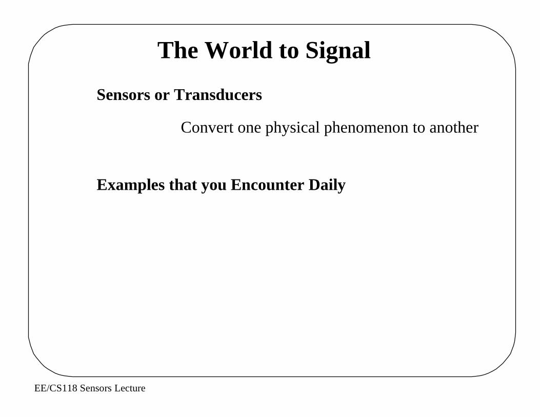
The World to Signal
Sensors or Transducers
Convert one physical phenomenon to another
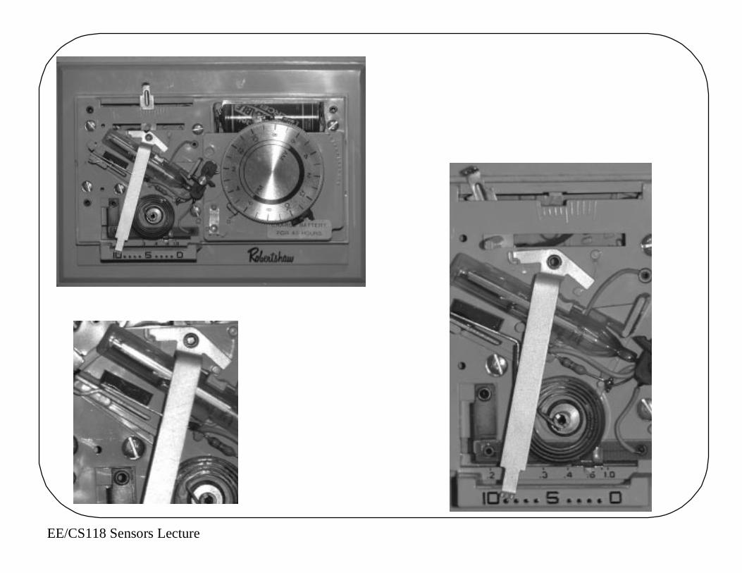
Examples that you Encounter Daily
EE/CS118 Sensors Lecture

EE/CS118 Sensors Lecture
What can the Microcontroller Measure ?
EE/CS118 Sensors Lecture
Basic Sensors: Light
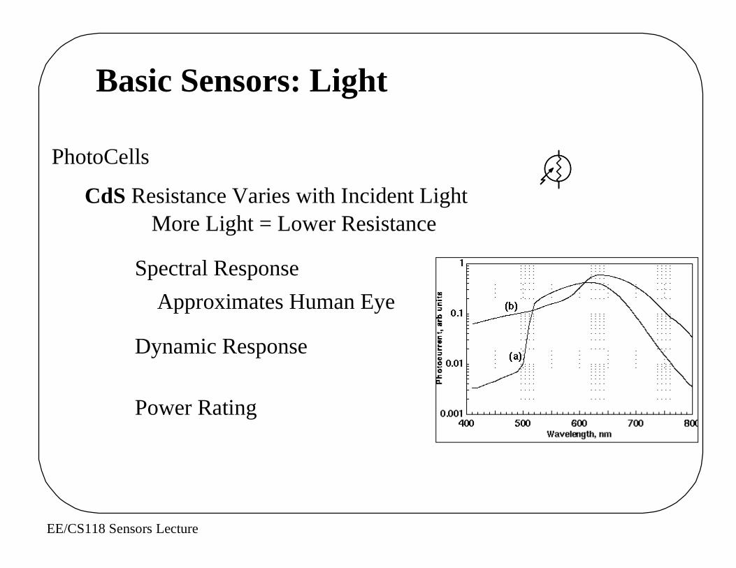
PhotoCells
CdS Resistance Varies with Incident LightMore Light = Lower Resistance
Spectral Response
Approximates Human Eye
Dynamic Response
Power Rating
EE/CS118 Sensors Lecture
CdS Photocell Specifications
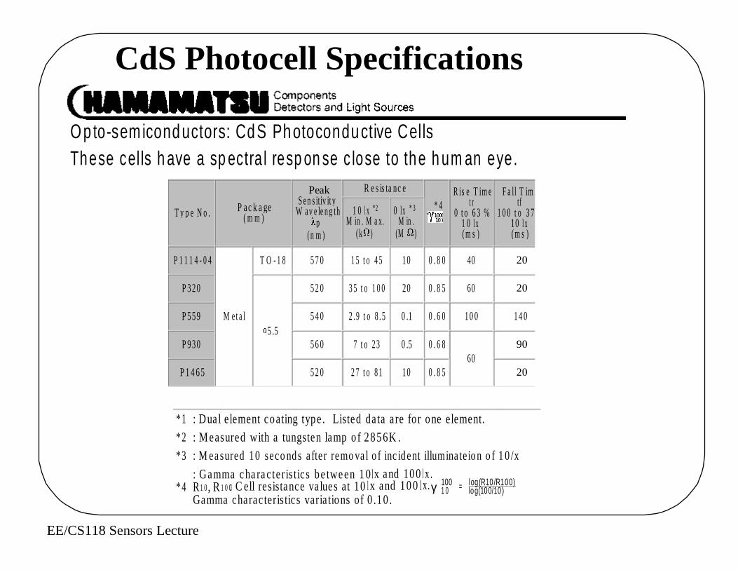
O p to-sem icond uctors: Cd S Ph otocondu ctive CellsThese cel ls h ave a sp ectra l resp on se c lose to the h um an eye.
T y p e N o . P ac k age ( m m )
PeakS en s itiv ity
W av e le ng thp
(n m)
R e s is ta nc e
* 4 R is e T im e
t r0 t o 6 3 %
1 0 lx(m s)
F a ll T imetf
1 0 0 t o 3 710 l x(m s)
1 0 l x *2
M in . M a x. ( k )
0 lx * 3 M in .
(M )
P 1 1 1 4 - 0 4
M e t a l
T O - 1 8 57 0 1 5 t o 4 5 10 0 . 8 0 40 20
P 320
5 .5
52 0 3 5 t o 1 0 0 20 0 . 8 5 60 20
P 559 54 0 2 .9 t o 8 .5 0 .1 0 . 6 0 10 0 14 0
P 930 56 0 7 t o 2 3 0 .5 0 . 6 860
90
P 1 4 65 52 0 2 7 t o 8 1 10 0 . 8 5 20
* 1 : Dual element coating type. Listed data are for one element.* 2 : Measured with a tungsten lamp o f 2856K .* 3 : M easured 10 seco nds a fter remo val o f inc ident illuminate ion o f 1 0 /x
* 4: Gamma cha racteristics be tween 1 0l x and 100l x .R1 0, R1 0 0: C ell resistance va lues at 10l x and 10 0l x. Gamma characteristics varia tions of 0 .10 .
γ 1001 0 = log(R10/R100)
log(100/10)
EE/CS118 Sensors Lecture
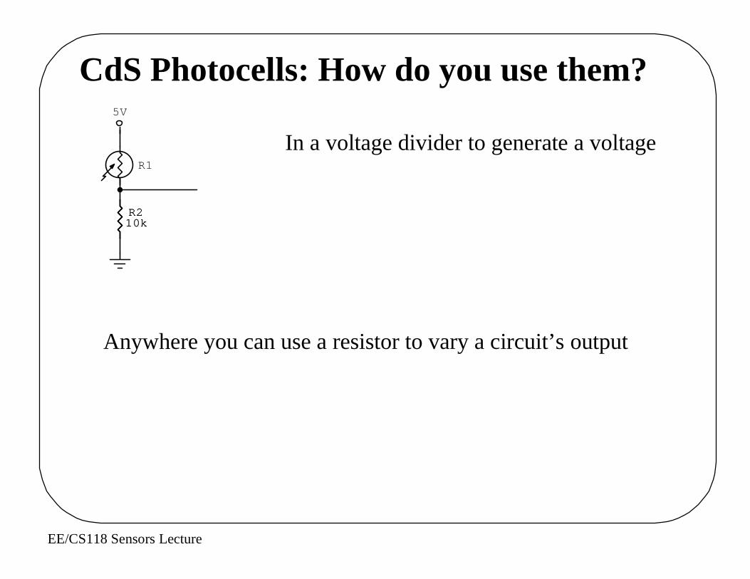
CdS Photocells: How do you use them?
In a voltage divider to generate a voltage
R210k
5V
R1
R210k
Anywhere you can use a resistor to vary a circuit’s output
EE/CS118 Sensors Lecture
Basic Sensors: Light
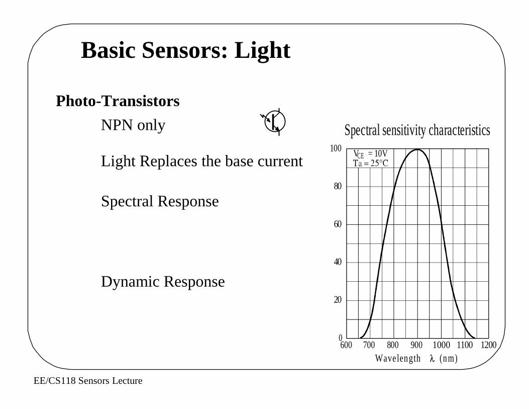
Photo-Transistors
NPN only
Light Replaces the base current
Spectral Response
Dynamic Response
Spectral sensitivity characteristics100
80
60
40
20
Wavelength (nm)700 800 900 1000 1100 1200
0600
VCE = 10V

EE/CS118 Sensors Lecture
0° 10° 20°
30°
40°
50°
60°
70°80°90°
Directivity characteristics
20
90
100
80
70
60
50
40
30 Rel
ativ
e se
nsiti
vity
S (%
)
Directional Characteristics
Sensitivity/Linearity
I CE(L) — L
Illuminance L (lx)
Col
lect
or p
hoto
cur
rent
I
CE(
L) (
mA
)
V CE = 10VTa = 25°CT = 2856K
10 3
10 2
10
1
10 –1
10 10 3 10 410 210 –21

EE/CS118 Sensors Lecture
LTR3208EData Sheet
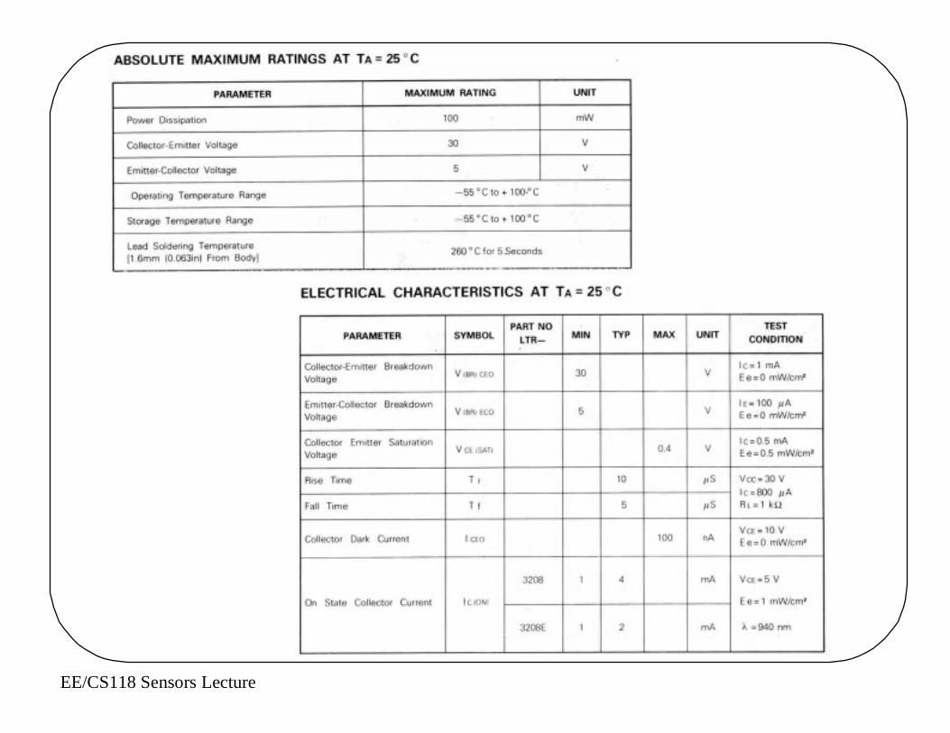
EE/CS118 Sensors Lecture

EE/CS118 Sensors Lecture
Phototransistors: How Do You Use Them?
5V
R11k
Q1
5V
R11k
Q1
Simple Ways
EE/CS118 Sensors Lecture
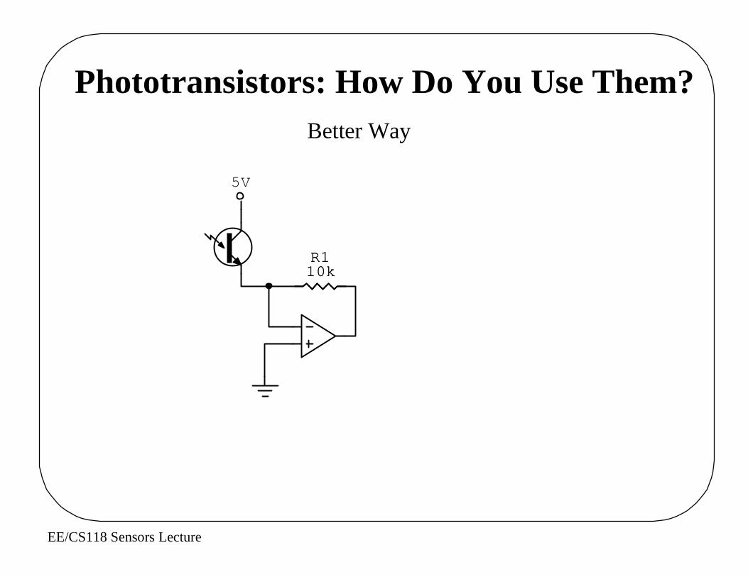
Phototransistors: How Do You Use Them?Better Way
R110k
5V
R110k
EE/CS118 Sensors Lecture
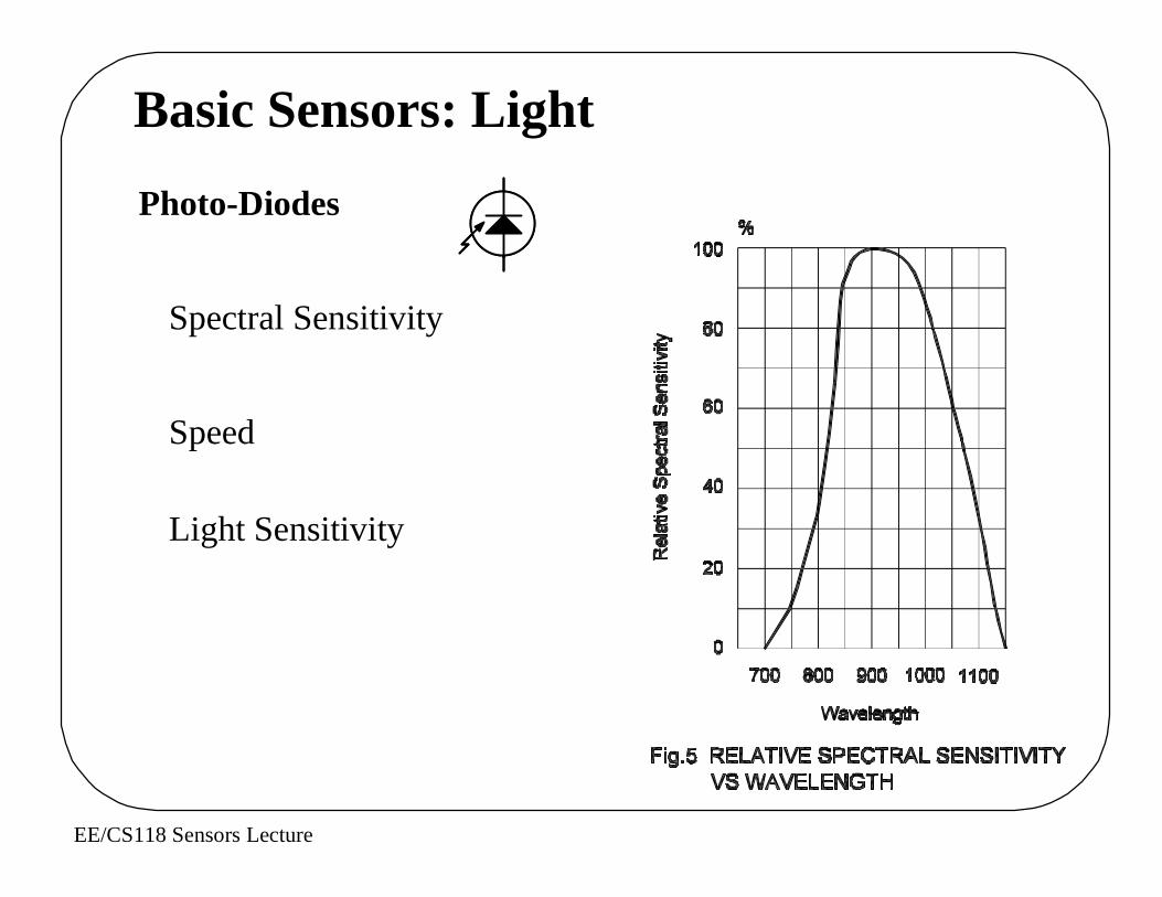
Basic Sensors: Light
Photo-Diodes
Spectral Sensitivity
Speed
Light Sensitivity

EE/CS118 Sensors Lecture
Wide Dynamic Range
EE/CS118 Sensors Lecture
EE/CS118 Sensors Lecture
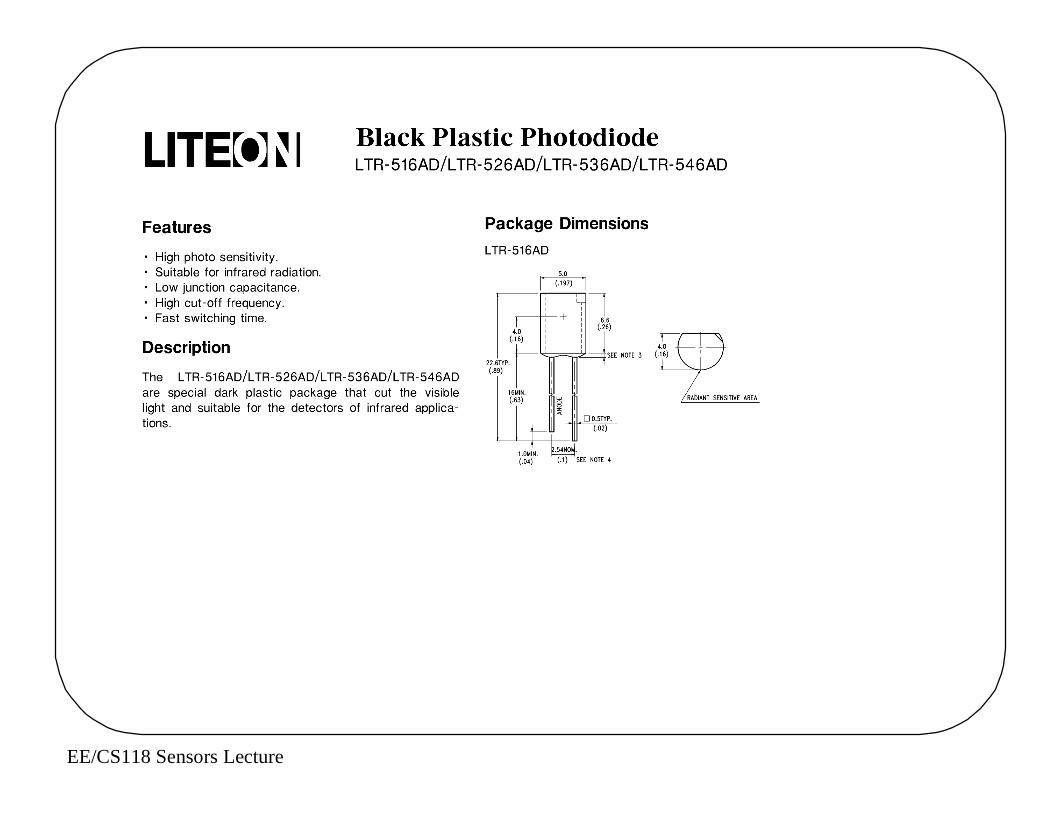
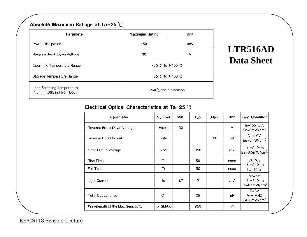
LTR516ADData Sheet
EE/CS118 Sensors Lecture
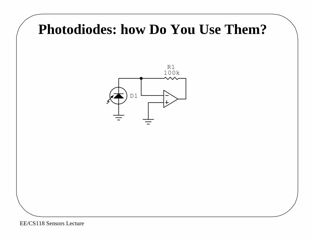
Photodiodes: how Do You Use Them?
D1
R1100k
EE/CS118 Sensors Lecture
Basic Sensors: Magnetic Field
Simplest: a Reed Switch
EE/CS118 Sensors Lecture
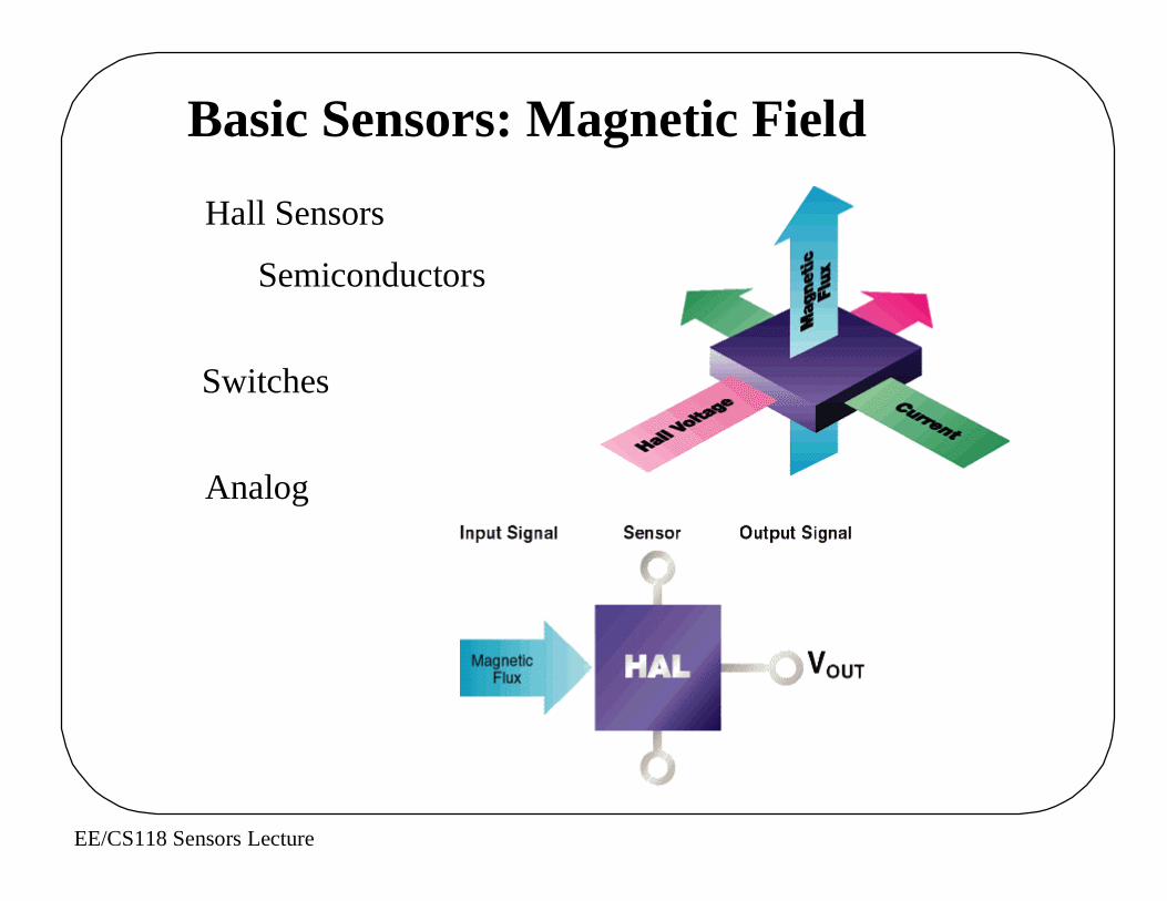
Basic Sensors: Magnetic Field
Hall Sensors
Semiconductors
Switches
Analog

EE/CS118 Sensors Lecture
Uni-Polar
BiPolar
Linear

EE/CS118 Sensors Lecture
Linear SensorMeasuring Rotation
DigitalUsing Bias Magnet
EE/CS118 Sensors Lecture
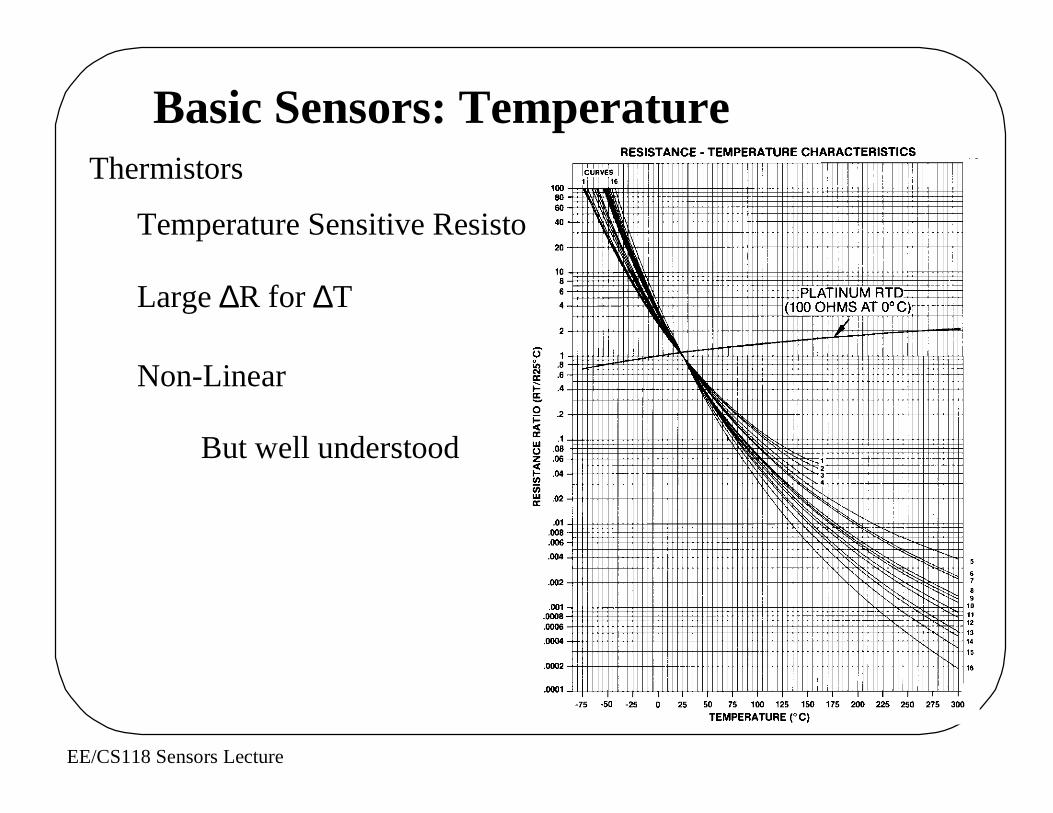
Basic Sensors: TemperatureThermistors
Temperature Sensitive Resistor
Large ∆R for ∆T
Non-Linear
But well understood
EE/CS118 Sensors Lecture
Basic Sensors: Temperature
Platinuum Restive Temperature Devices
RTDs
Wide Temperature Range
Extremely Linear
Very Stable
Not Very Sensitive
EE/CS118 Sensors Lecture
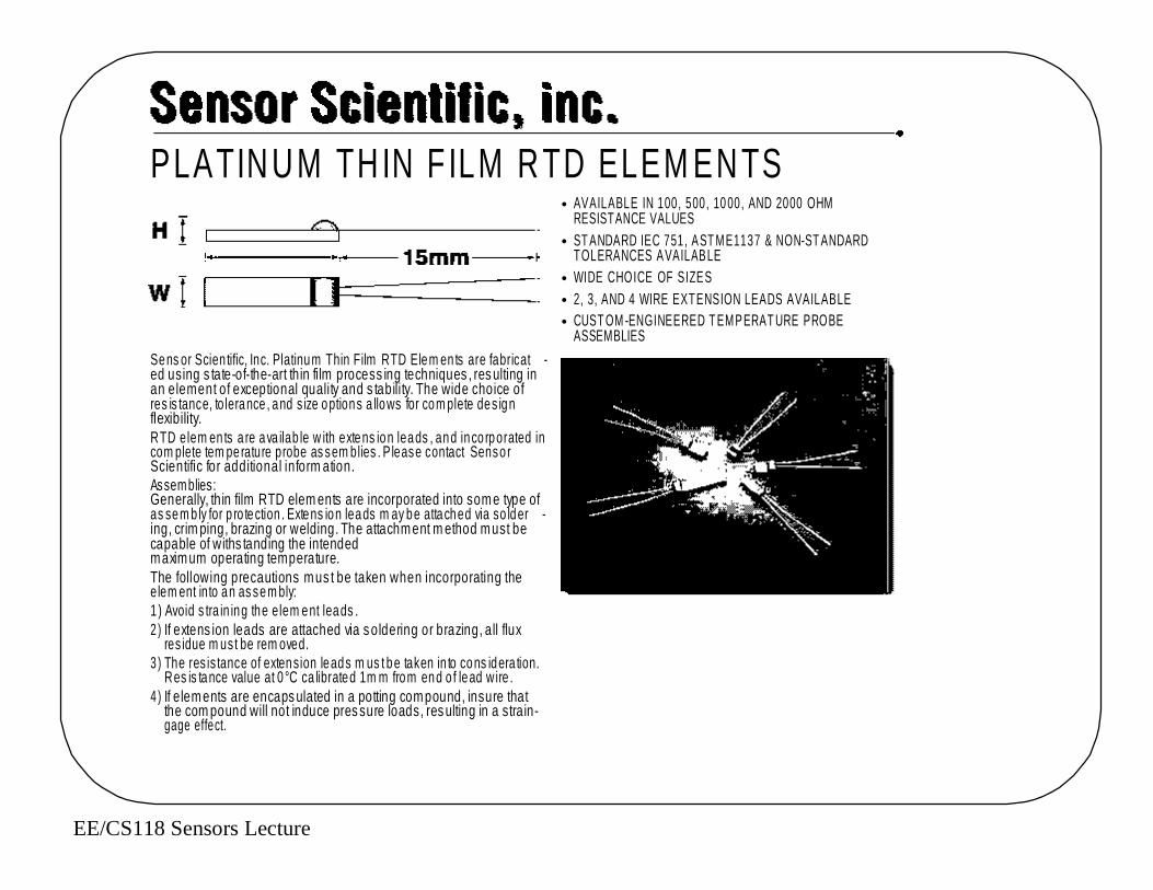
• AVAILABLE IN 100, 500, 10 00, AND 2000 OHM RESISTANCE VALUES
• ST ANDARD IEC 751, AST ME1137 & NON-ST ANDARDTOLERANCES AVAILABLE
• WIDE CHOICE OF SIZES• 2, 3, AND 4 WIRE EXTENSION LEADS AVAILABLE• CUST OM -ENGINEERED T EMPERAT URE PROBE
ASSEMBLIES
PLATINUM THIN F ILM RTD ELEM ENTS
Sens or Scien tific, Inc. Platinum Thin Film RTD Elem en ts are fabricat -ed using s tate-of-the-art thin film process ing techniques , res ulting inan element of exceptional quality and s tability. The wide choice ofres is tance, to lerance , and s ize options a llows for com plete des ignflexibility.RTD elem en ts a re ava ilab le w ith extens ion leads , and inco rporated incom plete tem perature probe as sem blies . P lease contact Senso rScientific for additional inform ation.Assemblies: Generally, thin film RTD elem ents are incorporated into some type ofas sem b ly for p ro tection . Extens ion leads m ay be attached via so lder -ing, crim ping, brazing or welding. The attachment m ethod must becapable of withs tanding the intended maximum operating temperature.The following precautions mus t be taken when incorporating theelem ent into an as sem bly:1 ) Avoid s tra in ing the elem ent leads .2 ) If extens ion leads are attached via s oldering or brazing, all flux
res idue m us t be rem oved.3 ) The res is tance of extension leads m us t be taken in to cons idera tion.
Res is tance value at 0 °C ca librated 1m m from end o f lead w ire . 4 ) If elements are encaps ulated in a potting compound, insure that
the com pound will not induce pres sure loads, res ulting in a strain-gage effect.

EE/CS118 Sensors Lecture
Resis tance L W H at 0 Deg. C. Length Width He igh t Part Num ber
ohms mm mm mm100 5.0 +/- 0 .2 1 .0 +/- 0 .2 1.3 +/- 0 .2 P01 lln 1100 5 .0 +/- 0 .2 1 .5 +/- 0 .2 1.3 +/- 0 .2 P01 lln 2100 2 .3 +/- 0 .2 2 .0 +/- 0 .2 1.3 +/- 0 .2 P01 lln 3100 5 .0 +/- 0 .2 2 .0 +/- 0 .2 1.3 +/- 0 .2 P01 lln 4100 10.0 +/- 0 .2 2 .0 +/- 0 .2 1.3 +/- 0 .2 P01 lln 5100 5 .0 +/- 0 .2 4 .0 +/- 0 .2 1.3 +/- 0 .2 P01 lln 6100 1 .6+/- 0 .15 1.25 +/- 0.1 1 .00 +/- 0 .2 P01 ll M7500 5 .0 +/- 0 .2 2 .0 +/- 0 .2 1.3 +/- 0 .2 P05 lln 1500 10.0 +/- 0 .2 2 .0 +/- 0 .2 1.3 +/- 0 .2 P05 lln 2500 5 .0 +/- 0 .2 4 .0 +/- 0 .2 1.3 +/- 0 .2 P05 lln 3
1000 4 .0 +/- 0 .2 2 .0 +/- 0 .2 1.3 +/- 0 .2 P10 lln 11000 10.0 +/- 0 .2 2 .0 +/- 0 .2 1 .3 +/- 0 .2 P10 lln 21000 5 .0 +/- 0 .2 4 .0 +/- 0 .2 1.3 +/- 0 .2 P10 lln 31000 1 .6+/- 0 .15 1.25 +/- 0.1 1 .00 +/- 0 .2 P10 ll M42000 10.0 +/- 0 .2 2 .0 +/- 0 .2 1.3 +/- 0 .2 P20 lln 4
ll - To leranc e 0 B = D IN B n - Te m p era tu re R a nge01 =1 /1 0 D IN B at 0 °C 0 5 = A S TM B L = -50 to + 4 00 D e g C0 2 = 1 /5 D IN B a t 0 °C 06 = 3 /2 D IN B a t 0° C M = -5 0 t o + 55 0 D eg C0 3 = 1 /4 D IN B a t 0 °C 07 = 2 D IN B at 0 °C H = -5 0 to + 6 00 D e g C0 4 = 1 /3 D IN B a t 0 °C 08 = 5 D IN B at 0 °C0A = 1/2 D IN B (D IN A) at 0 °C 0 9 = 10 D IN B a t 0 °C
R es is tanc e v a lue at 0 °C ca libra te d 1m m f rom e nd o flea d wire. D IN = IEC 751
Limited Range of Resistances
∆R proportional to R at 0°C
EE/CS118 Sensors Lecture
Measuring Position
Translate Movement to ??? To Voltage
What are examples of ???
EE/CS118 Sensors Lecture
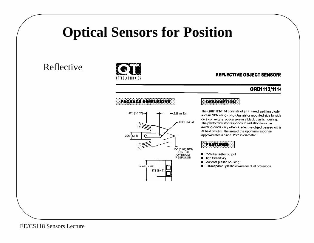
Optical Sensors for Position
Reflective
EE/CS118 Sensors Lecture
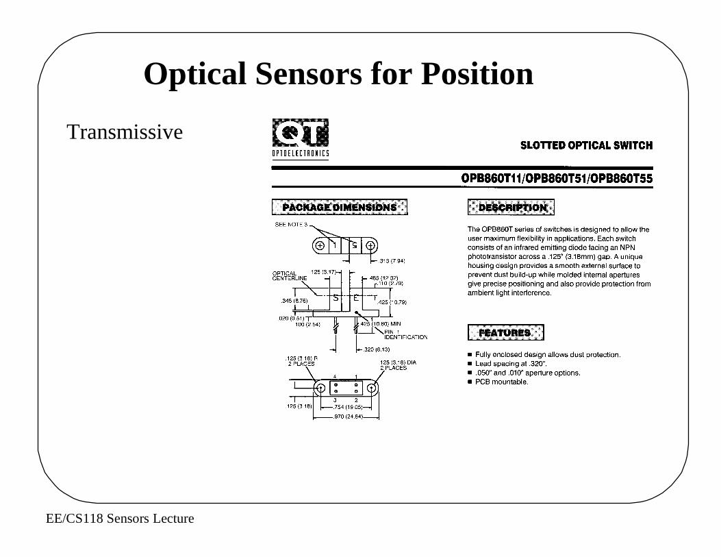
Optical Sensors for Position
Transmissive
EE/CS118 Sensors Lecture
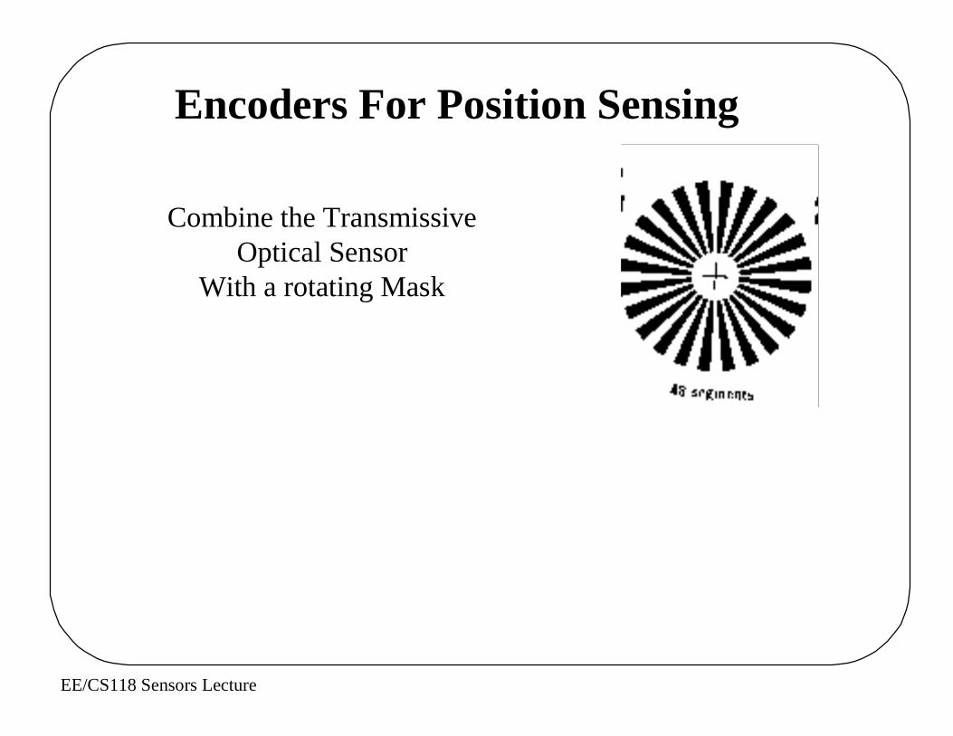
Encoders For Position Sensing
Combine the TransmissiveOptical Sensor
With a rotating Mask
EE/CS118 Sensors Lecture
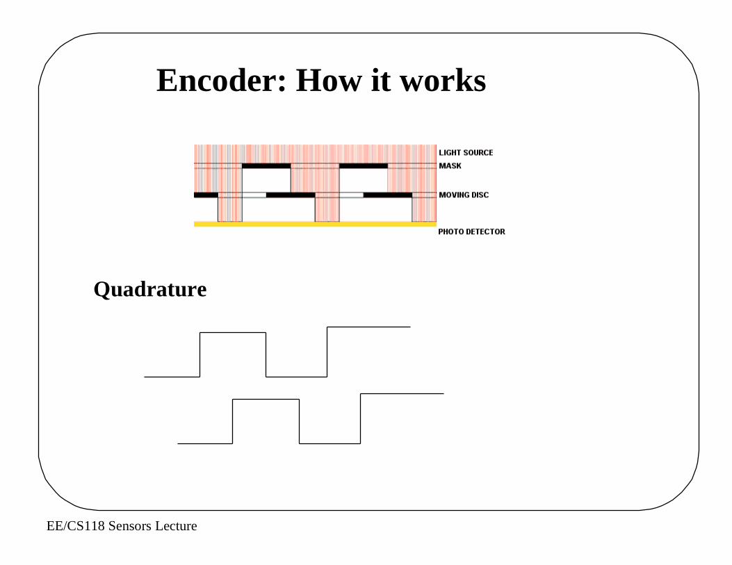
Encoder: How it works
Quadrature

EE/CS118 Sensors Lecture
Encoders: Where Do You Find Them?
Printers
Disk Drives