
Reconstruction with Depth and Color cameras for 3D Autostereoscopic Consumer Displays
Visual Computing SystemsCMU 15-869, Fall 2013
Lecture 19:
Depth Cameras
CMU 15-869, Fall 2013
Continuing theme: computational photography
▪ Cameras capture light, then extensive processing produces the desired image
▪ Today:- Capturing scene depth in addition to light intensity

CMU 15-869, Fall 2013
Scene Understanding
Why might we want to know the depth of scene objects?
Mapping
Navigation
Segmentation
Object tracking
Credit: Blashko et al. CVPR 13 Tutorial
CMU 15-869, Fall 2013
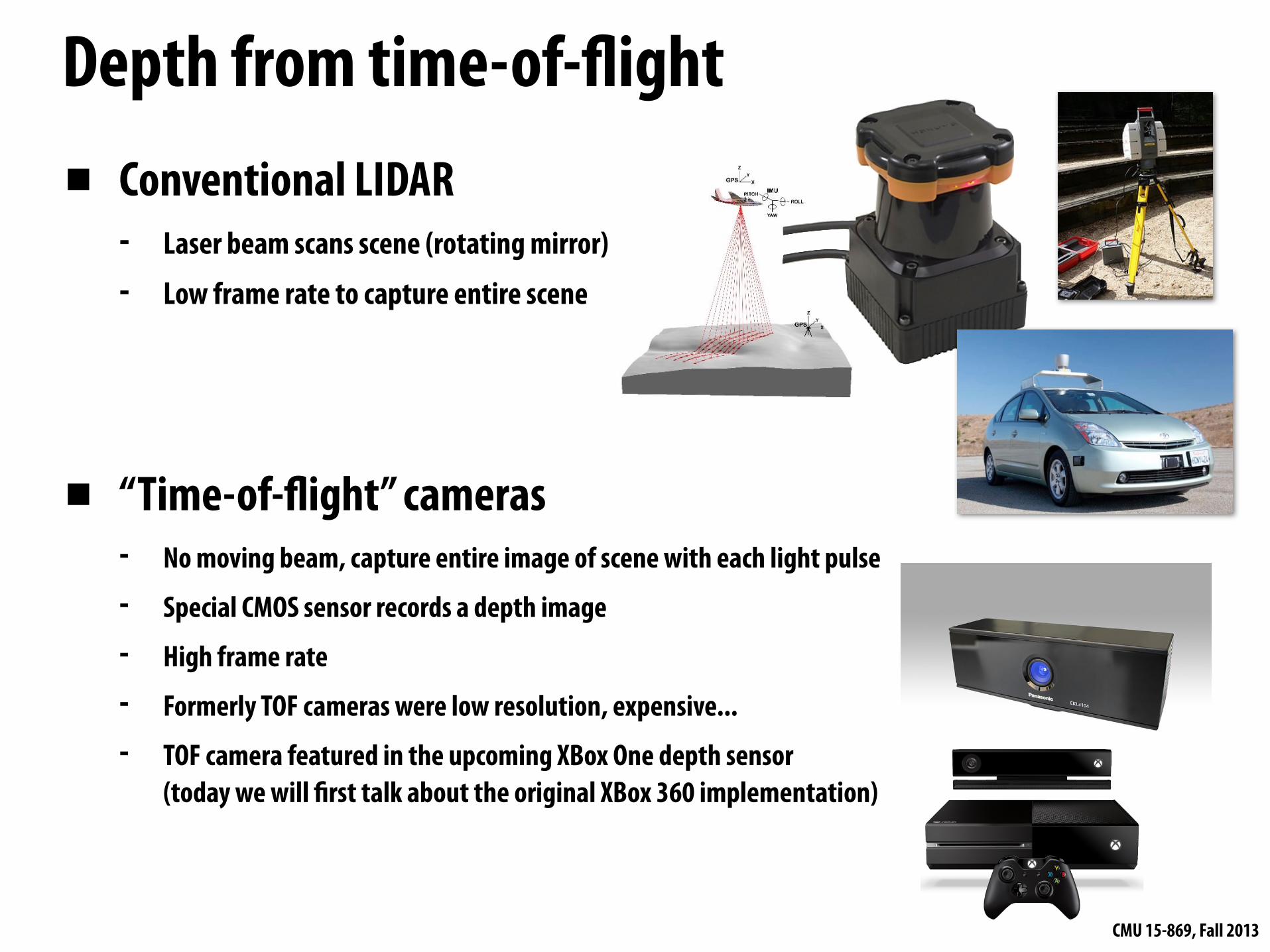
▪ Conventional LIDAR- Laser beam scans scene (rotating mirror)- Low frame rate to capture entire scene
▪ “Time-of-!ight” cameras- No moving beam, capture entire image of scene with each light pulse
- Special CMOS sensor records a depth image
- High frame rate
- Formerly TOF cameras were low resolution, expensive...
- TOF camera featured in the upcoming XBox One depth sensor(today we will "rst talk about the original XBox 360 implementation)
Depth from time-of-!ight
CMU 15-869, Fall 2013
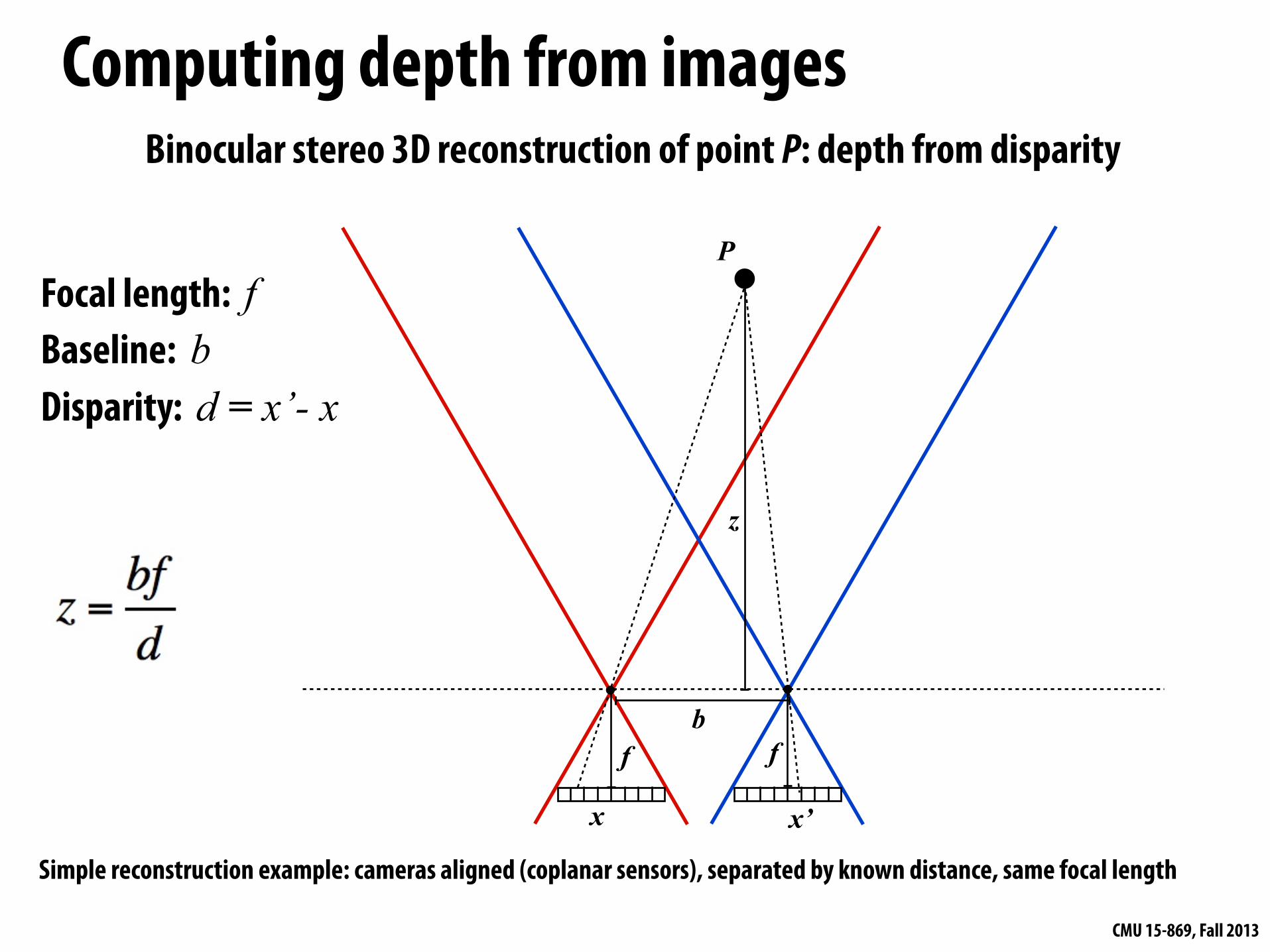
Computing depth from imagesBinocular stereo 3D reconstruction of point P: depth from disparity
P
x x’
ffb
z
Focal length: fBaseline: b Disparity: d = x’- x
Simple reconstruction example: cameras aligned (coplanar sensors), separated by known distance, same focal length
CMU 15-869, Fall 2013
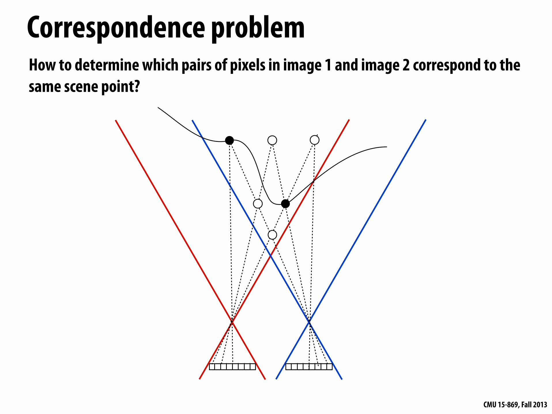
Correspondence problemHow to determine which pairs of pixels in image 1 and image 2 correspond to the same scene point?
CMU 15-869, Fall 2013
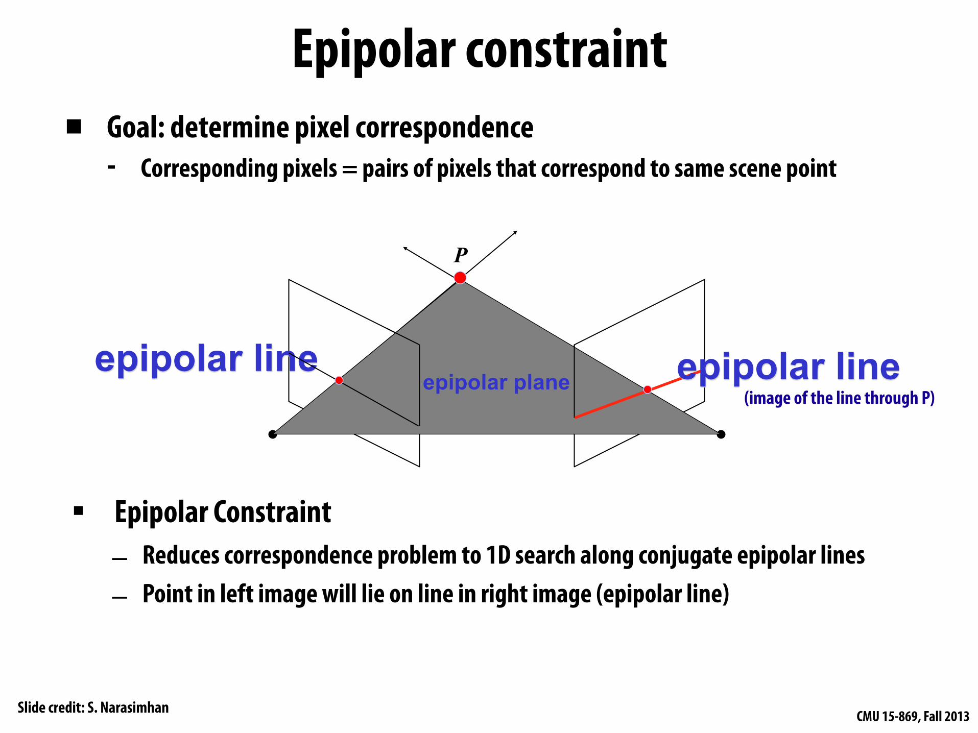
▪ Goal: determine pixel correspondence- Corresponding pixels = pairs of pixels that correspond to same scene point
▪ Epipolar Constraint– Reduces correspondence problem to 1D search along conjugate epipolar lines– Point in left image will lie on line in right image (epipolar line)
epipolar plane epipolar lineepipolar line
Epipolar constraint
Slide credit: S. Narasimhan
P
(image of the line through P)
CMU 15-869, Fall 2013
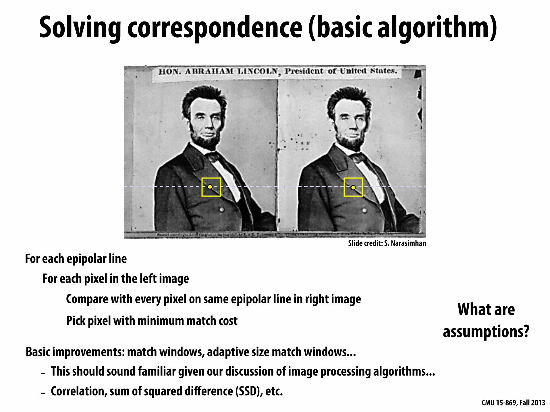
For each epipolar lineFor each pixel in the left image
Compare with every pixel on same epipolar line in right imagePick pixel with minimum match cost
Basic improvements: match windows, adaptive size match windows...- This should sound familiar given our discussion of image processing algorithms...- Correlation, sum of squared difference (SSD), etc.
Solving correspondence (basic algorithm)
What are assumptions?
Slide credit: S. Narasimhan
CMU 15-869, Fall 2013
Solving correspondence: robustness challenges
▪ Scene with no texture (many parts of the scene look the same)
▪ Non-lambertian surfaces (surface appearance is dependent upon view)
▪ Pixel pairs may not be present (point on surface is occluded from one view)
CMU 15-869, Fall 2013
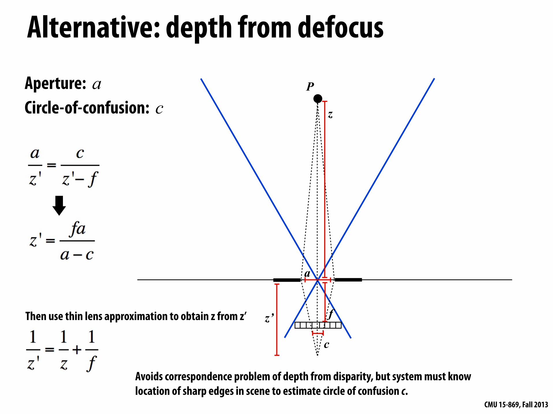
Alternative: depth from defocus
P
f
z
c
a
z’Then use thin lens approximation to obtain z from z’
Aperture: aCircle-of-confusion: c
Avoids correspondence problem of depth from disparity, but system must know location of sharp edges in scene to estimate circle of confusion c.
CMU 15-869, Fall 2013
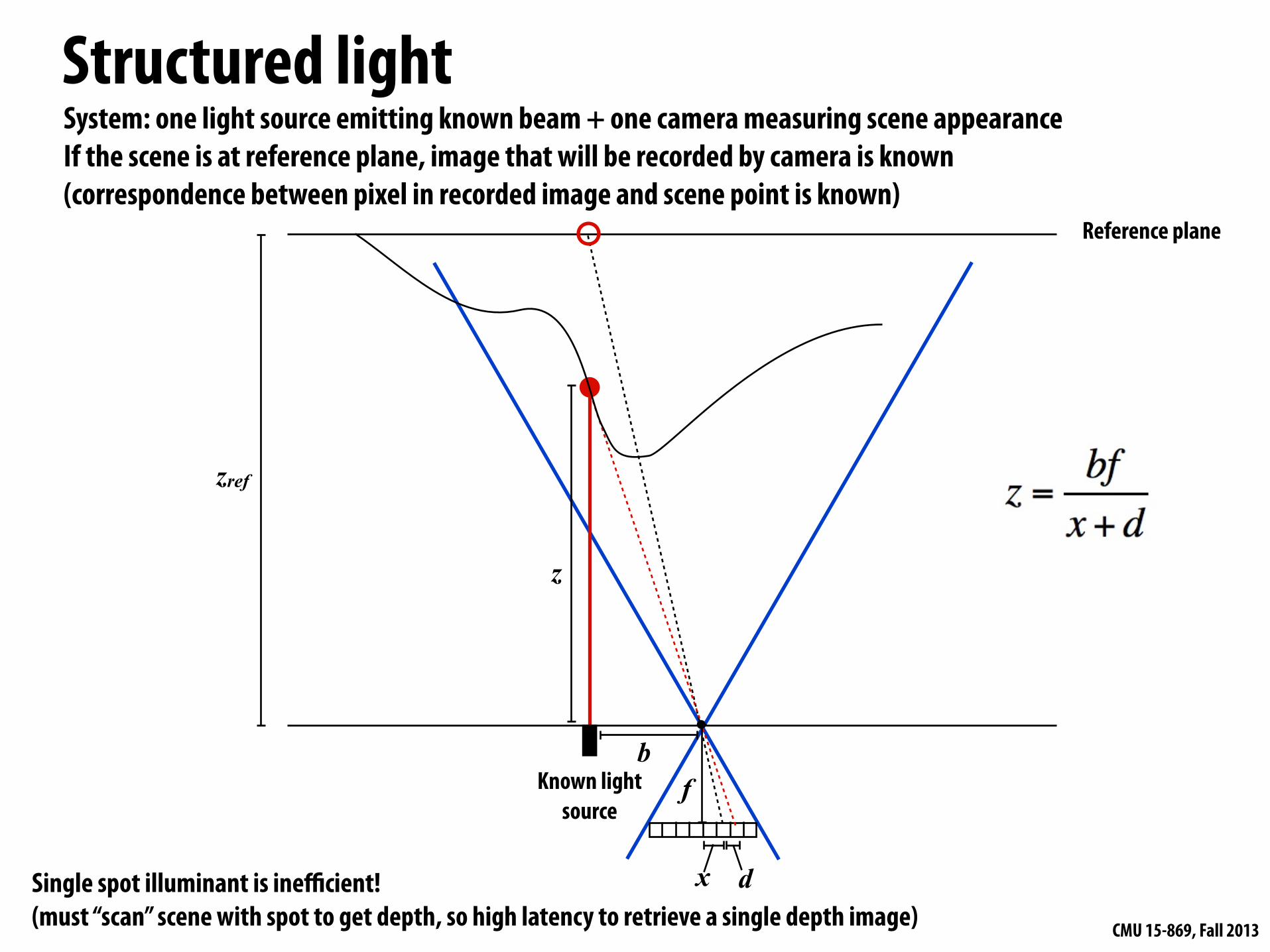
Structured light
z
zref
d
f
Reference plane
Known light source
b
System: one light source emitting known beam + one camera measuring scene appearance If the scene is at reference plane, image that will be recorded by camera is known(correspondence between pixel in recorded image and scene point is known)
Single spot illuminant is inefficient!(must “scan” scene with spot to get depth, so high latency to retrieve a single depth image)
x
CMU 15-869, Fall 2013
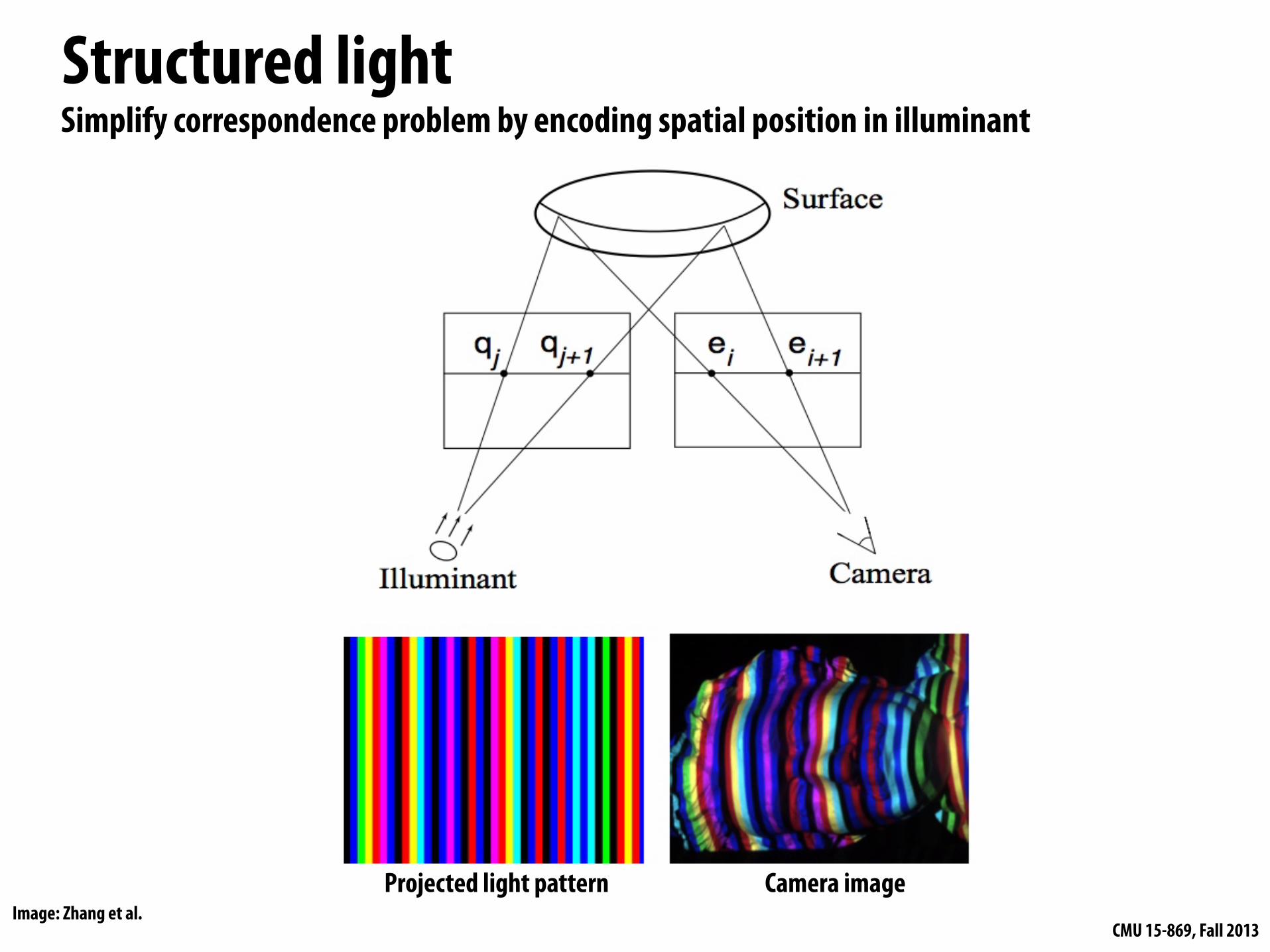
Structured lightSimplify correspondence problem by encoding spatial position in illuminant
Projected light pattern Camera imageImage: Zhang et al.
CMU 15-869, Fall 2013
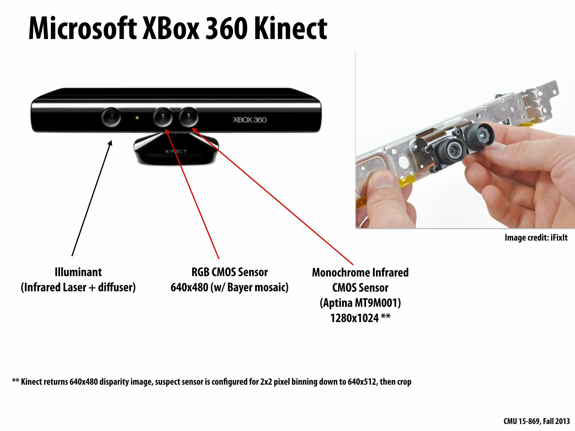
Microsoft XBox 360 Kinect
Illuminant(Infrared Laser + diffuser)
RGB CMOS Sensor640x480 (w/ Bayer mosaic)
Monochrome Infrared CMOS Sensor
(Aptina MT9M001)1280x1024 **
** Kinect returns 640x480 disparity image, suspect sensor is con"gured for 2x2 pixel binning down to 640x512, then crop
Image credit: iFixIt
CMU 15-869, Fall 2013Credit: www.futurepicture.org
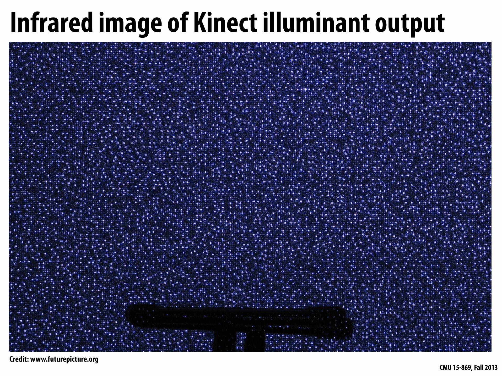
Infrared image of Kinect illuminant output

CMU 15-869, Fall 2013Credit: www.futurepicture.org
Infrared image of Kinect illuminant output
CMU 15-869, Fall 2013
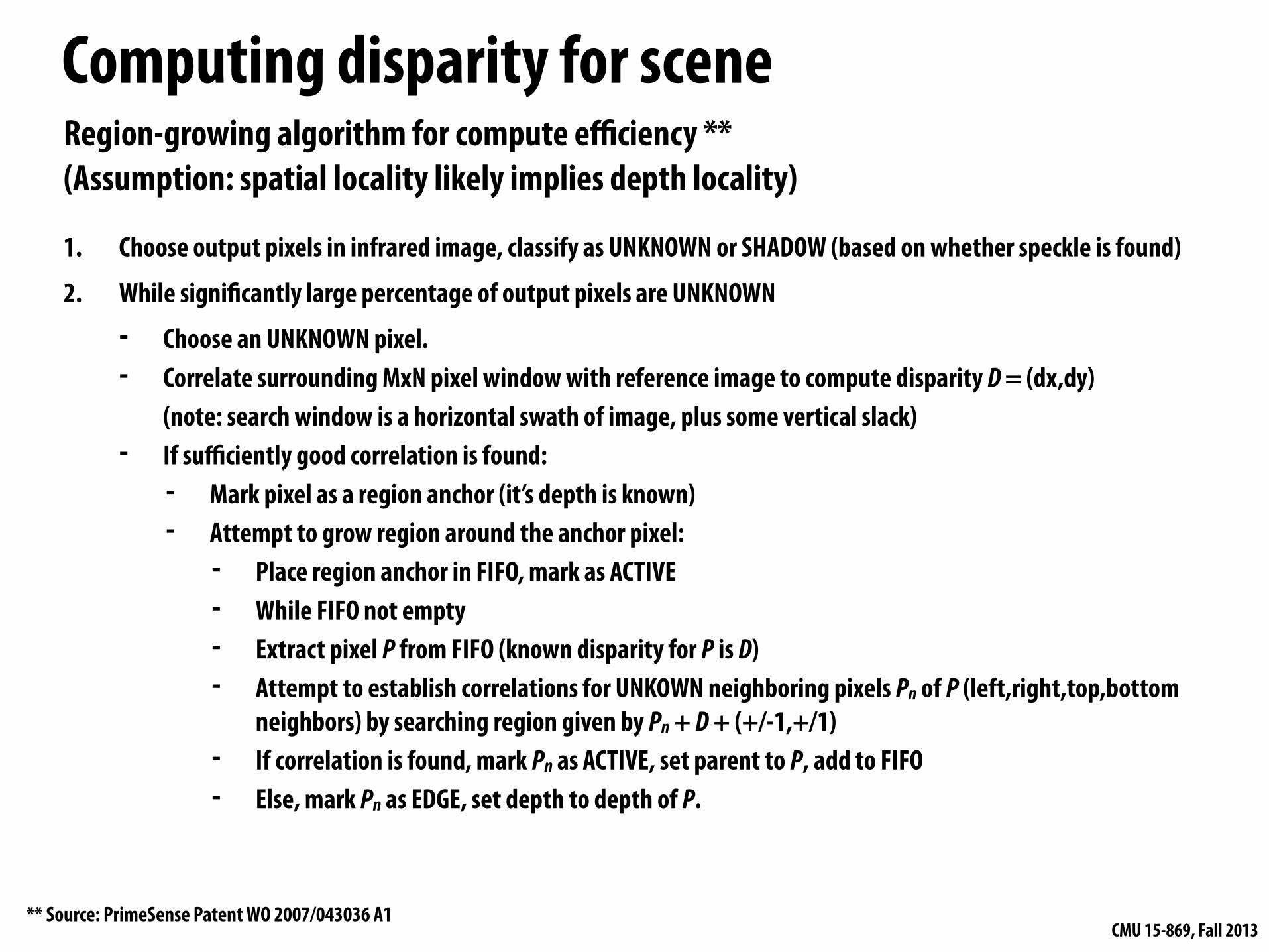
Computing disparity for scene
1. Choose output pixels in infrared image, classify as UNKNOWN or SHADOW (based on whether speckle is found)
2. While signi#cantly large percentage of output pixels are UNKNOWN
- Choose an UNKNOWN pixel.- Correlate surrounding MxN pixel window with reference image to compute disparity D = (dx,dy)
(note: search window is a horizontal swath of image, plus some vertical slack)- If sufficiently good correlation is found:
- Mark pixel as a region anchor (it’s depth is known)- Attempt to grow region around the anchor pixel:
- Place region anchor in FIFO, mark as ACTIVE- While FIFO not empty- Extract pixel P from FIFO (known disparity for P is D)- Attempt to establish correlations for UNKOWN neighboring pixels Pn of P (left,right,top,bottom
neighbors) by searching region given by Pn + D + (+/-1,+/1)- If correlation is found, mark Pn as ACTIVE, set parent to P, add to FIFO- Else, mark Pn as EDGE, set depth to depth of P.
** Source: PrimeSense Patent WO 2007/043036 A1
Region-growing algorithm for compute efficiency **(Assumption: spatial locality likely implies depth locality)
CMU 15-869, Fall 2013
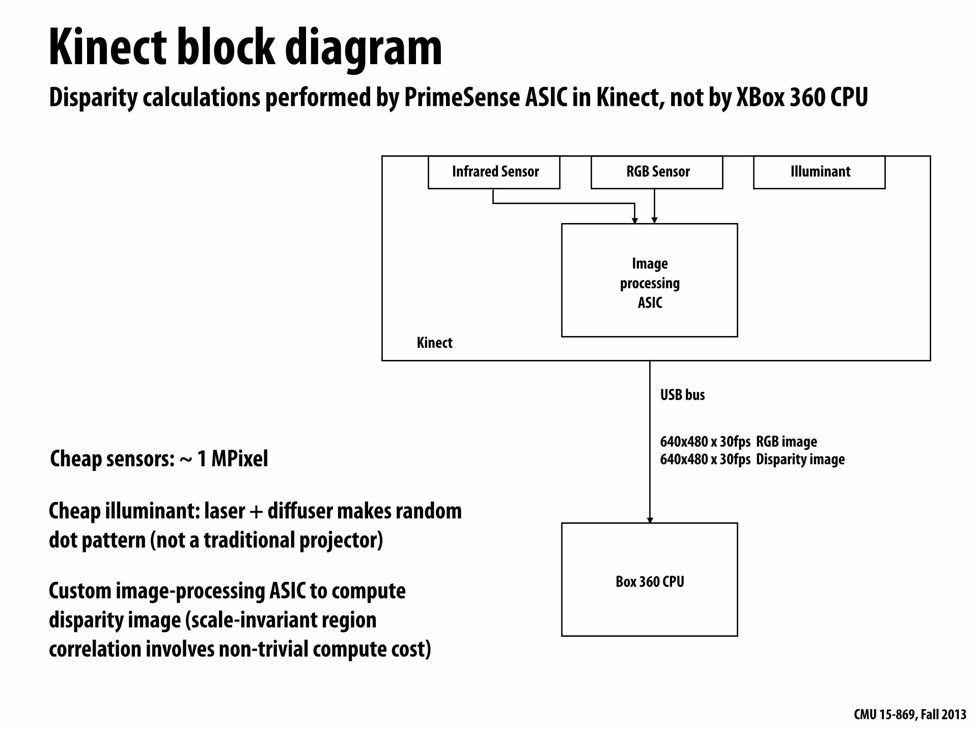
Kinect block diagram
Infrared Sensor RGB Sensor Illuminant
Image processing
ASIC
USB bus
Box 360 CPU
640x480 x 30fps RGB image 640x480 x 30fps Disparity image
Disparity calculations performed by PrimeSense ASIC in Kinect, not by XBox 360 CPU
Kinect
Cheap sensors: ~ 1 MPixel
Cheap illuminant: laser + diffuser makes random dot pattern (not a traditional projector)
Custom image-processing ASIC to compute disparity image (scale-invariant region correlation involves non-trivial compute cost)
CMU 15-869, Fall 2013
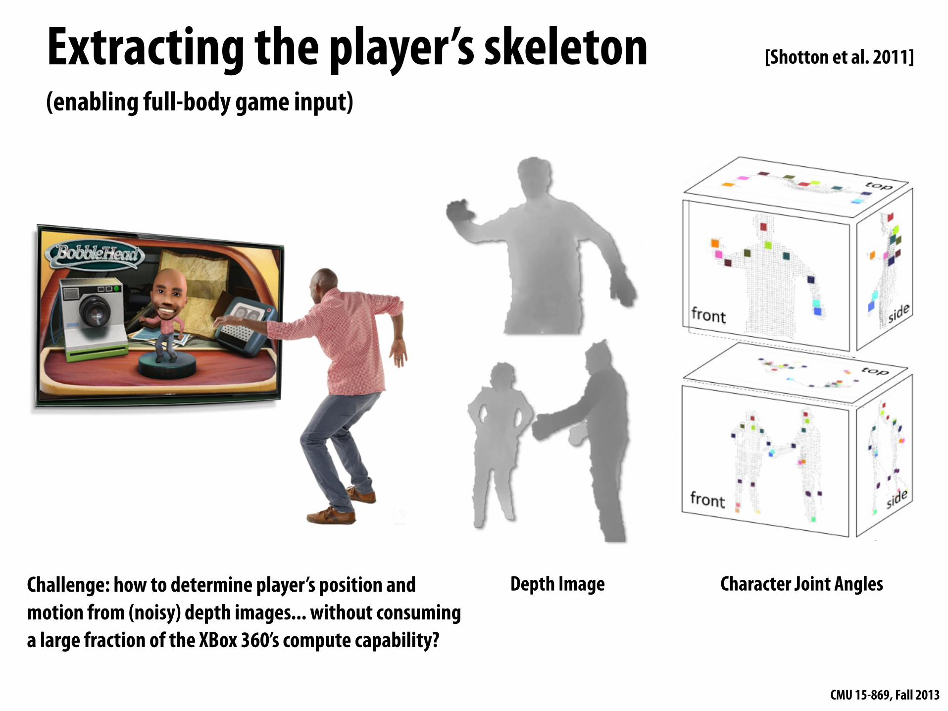
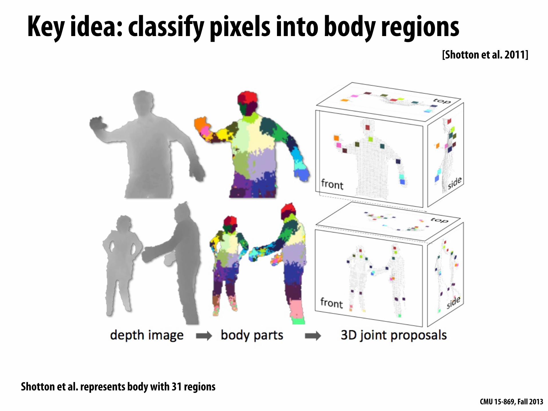
Extracting the player’s skeleton(enabling full-body game input)
Depth Image Character Joint AnglesChallenge: how to determine player’s position and motion from (noisy) depth images... without consuming a large fraction of the XBox 360’s compute capability?
[Shotton et al. 2011]
CMU 15-869, Fall 2013
Key idea: classify pixels into body regions
Shotton et al. represents body with 31 regions
[Shotton et al. 2011]
CMU 15-869, Fall 2013
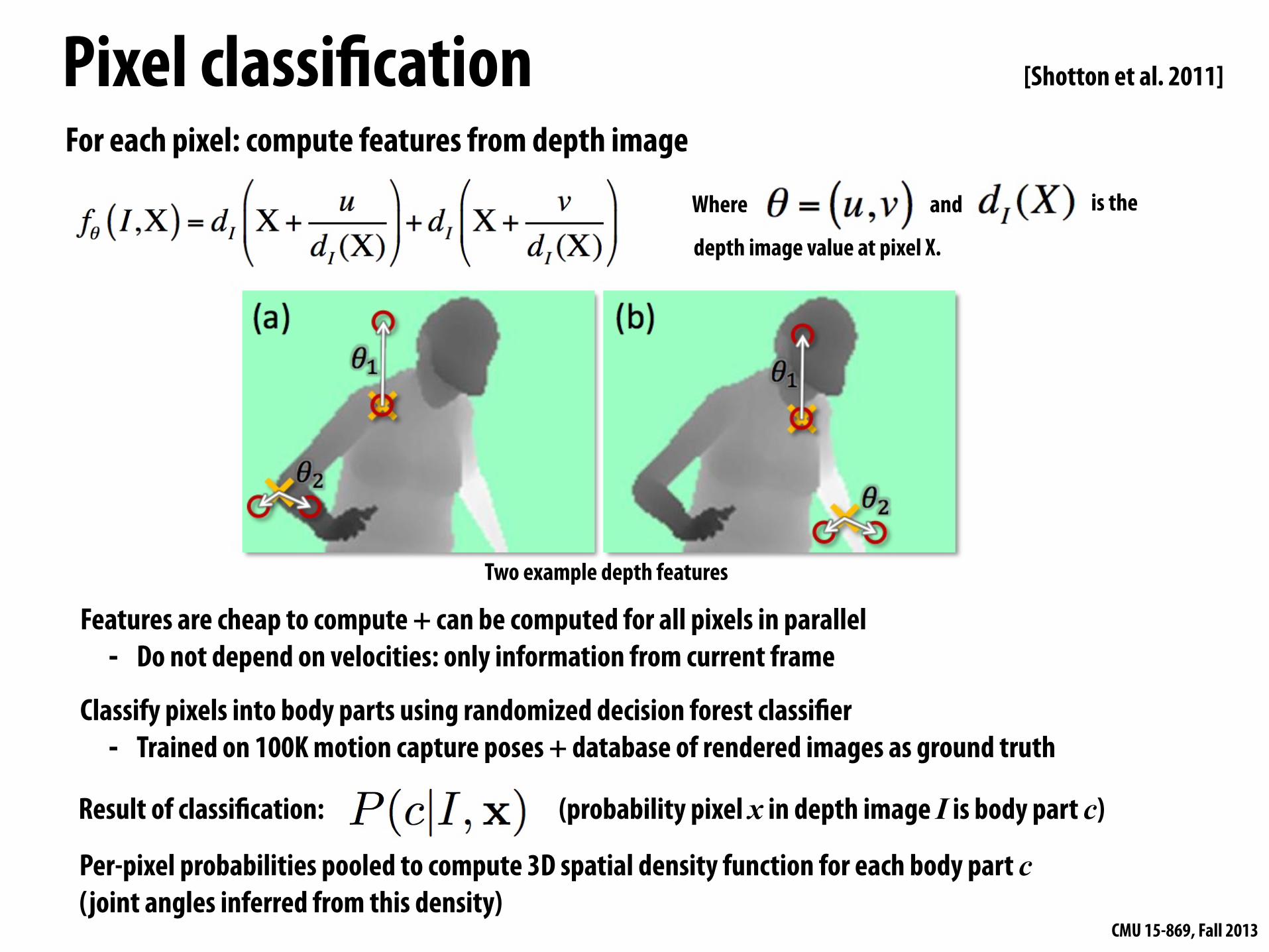
Pixel classi"cationFor each pixel: compute features from depth image
Classify pixels into body parts using randomized decision forest classi"er- Trained on 100K motion capture poses + database of rendered images as ground truth
Two example depth features
Per-pixel probabilities pooled to compute 3D spatial density function for each body part c(joint angles inferred from this density)
Result of classi"cation: (probability pixel x in depth image I is body part c)
[Shotton et al. 2011]
Where and is the
depth image value at pixel X.
Features are cheap to compute + can be computed for all pixels in parallel- Do not depend on velocities: only information from current frame
CMU 15-869, Fall 2013
Performance result▪ Real-time skeleton estimation from depth image requires < 10%
of Xbox 360 CPU
▪ XBox GPU-based implementation @ 200Hz (research implementation described in publication, not used in product)- Actual XBox 360 product implementation is likely far more efficient
CMU 15-869, Fall 2013
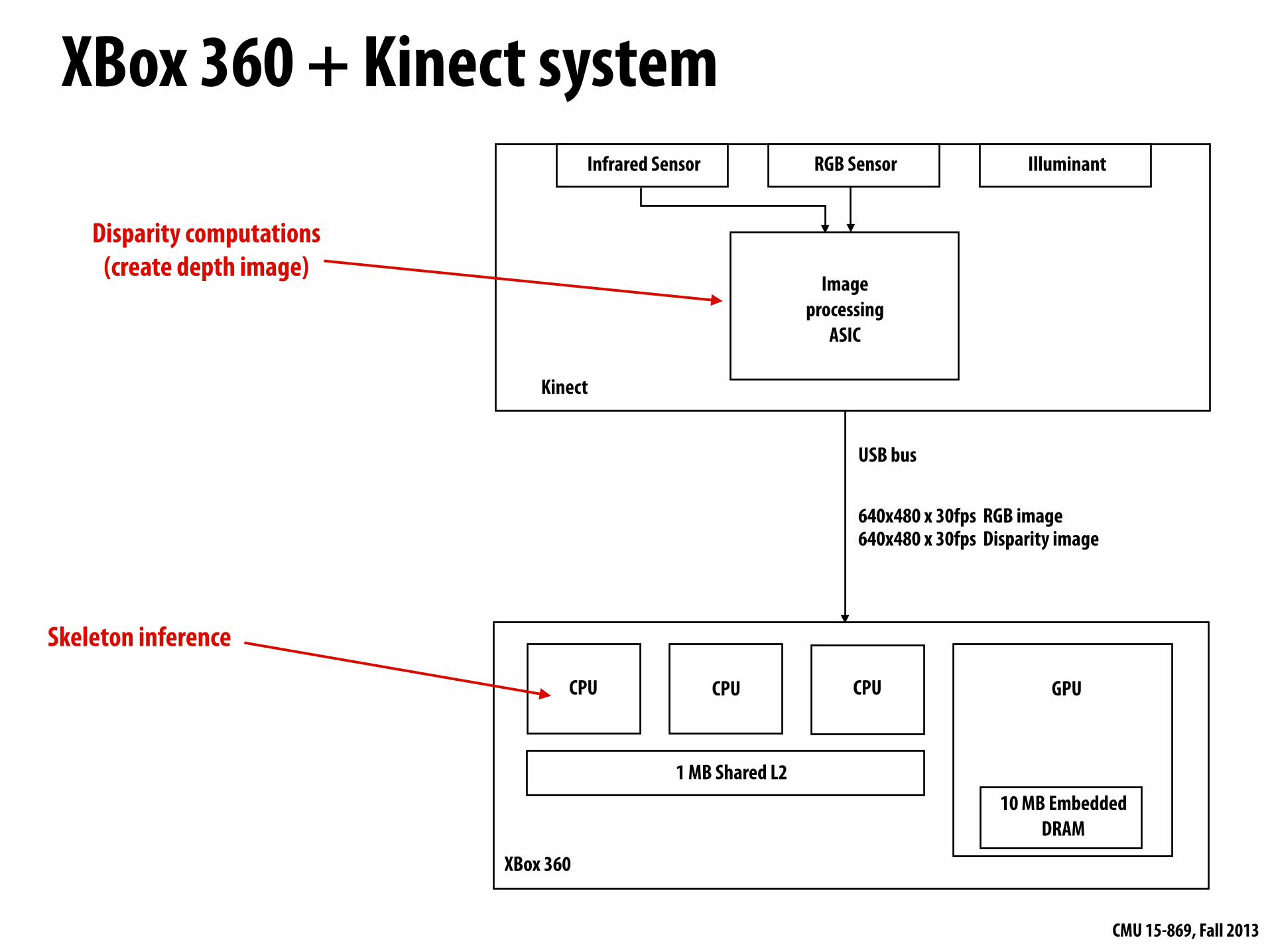
XBox 360 + Kinect systemInfrared Sensor RGB Sensor Illuminant
Image processing
ASIC
USB bus
XBox 360
640x480 x 30fps RGB image 640x480 x 30fps Disparity image
Kinect
Disparity computations(create depth image)
CPU CPU CPU GPU
1 MB Shared L210 MB Embedded
DRAM
Skeleton inference
CMU 15-869, Fall 2013
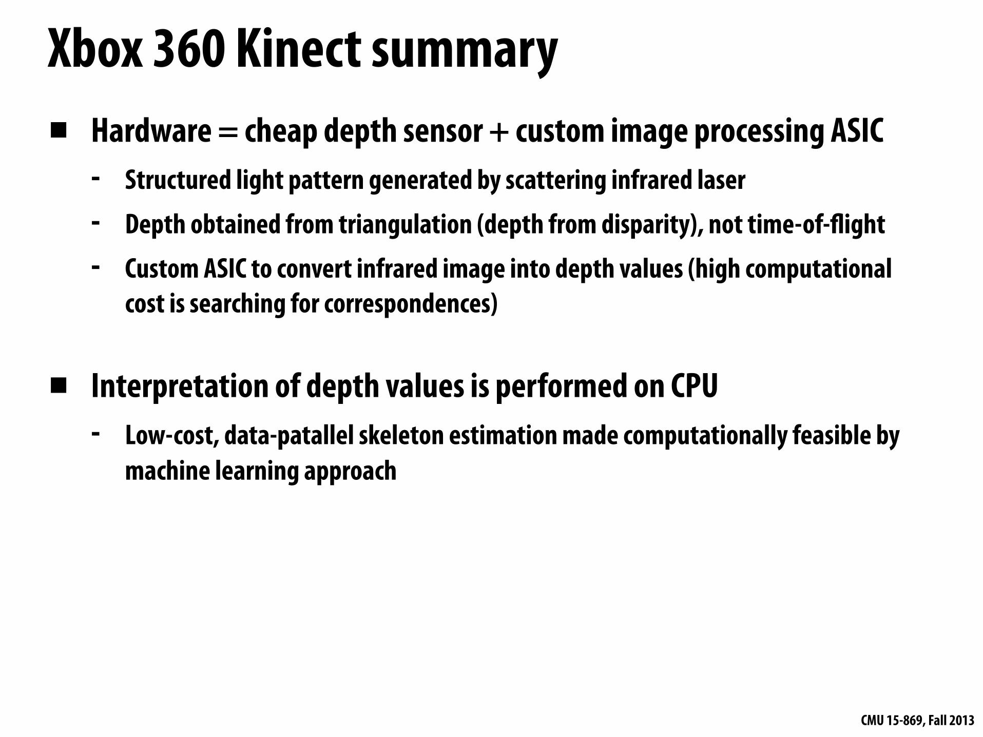
Xbox 360 Kinect summary▪ Hardware = cheap depth sensor + custom image processing ASIC
- Structured light pattern generated by scattering infrared laser- Depth obtained from triangulation (depth from disparity), not time-of-!ight- Custom ASIC to convert infrared image into depth values (high computational
cost is searching for correspondences)
▪ Interpretation of depth values is performed on CPU- Low-cost, data-patallel skeleton estimation made computationally feasible by
machine learning approach

CMU 15-869, Fall 2013
Xbox One Sensor▪ Time-of-!ight sensor (not based on structured light like the original Kinect)
▪ 1080p depth sensing + wider "eld-of-view than original Kinect
▪ “Computer vision” challenges in obtaining high-quality signal:- Flying pixels- Segmentation- Motion blur
Another TOF camera: Creative Depth Camera
CMU 15-869, Fall 2013
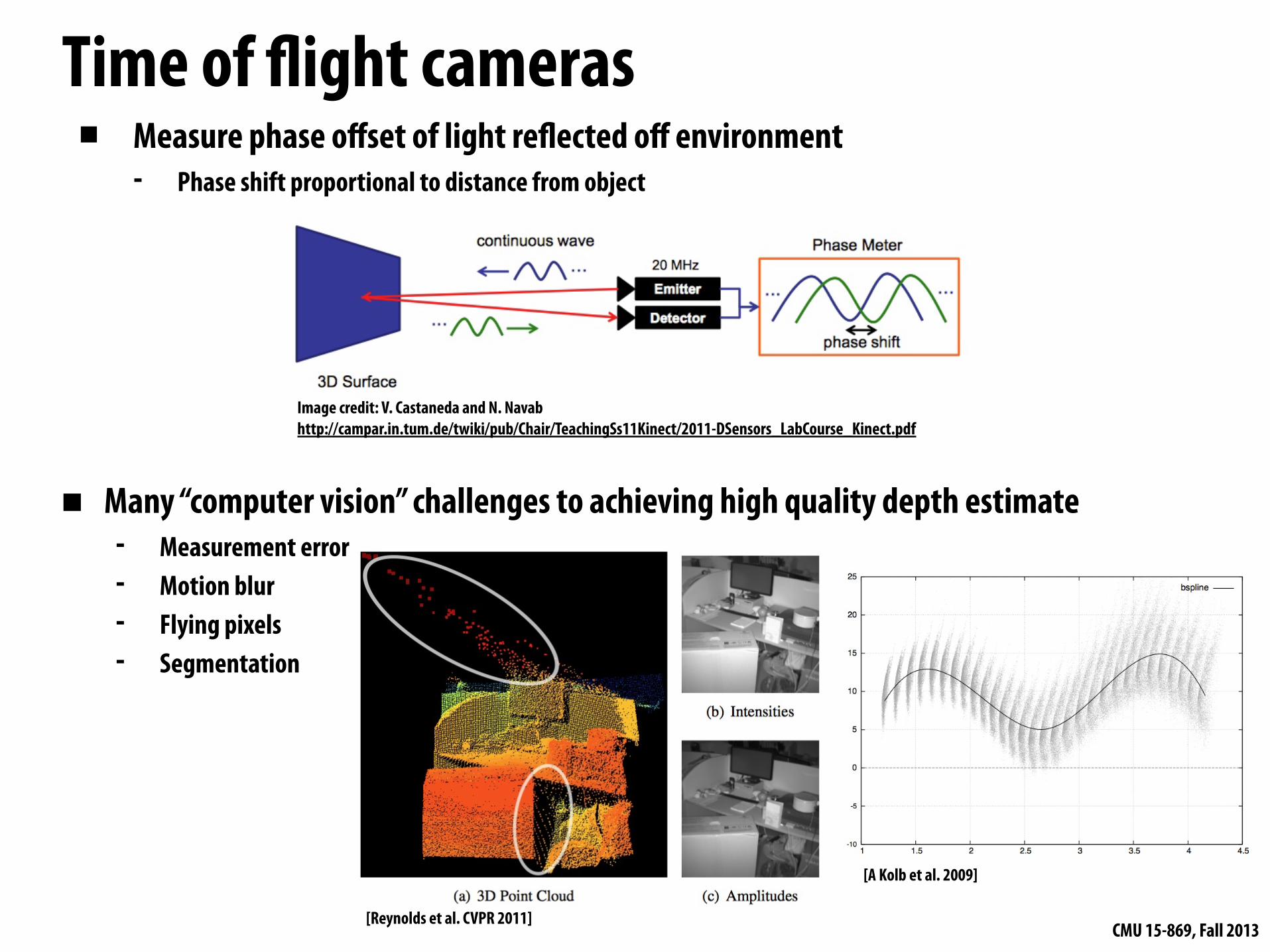
Time of !ight cameras▪ Measure phase offset of light re!ected off environment
- Phase shift proportional to distance from object
Image credit: V. Castaneda and N. Navabhttp://campar.in.tum.de/twiki/pub/Chair/TeachingSs11Kinect/2011-DSensors_LabCourse_Kinect.pdf
▪ Many “computer vision” challenges to achieving high quality depth estimate- Measurement error- Motion blur- Flying pixels- Segmentation
[Reynolds et al. CVPR 2011]
[A Kolb et al. 2009]
CMU 15-869, Fall 2013
Reading▪ KinectFusion: Real-time 3D Reconstruction and interaction Using a Moving
Depth Camera. S. Izadi et al. UIST 11- Note: may wish to Google ICP algorithm (iterative closest point)


![Occlusion-Aware Depth Estimation Using Light-Field Cameras · Depth from Light-Field Cameras: Perwass and Wiet-zke [18] proposed using correspondence techniques to esti-mate depth](https://static.fdocuments.us/doc/165x107/5ff80a4f233847279f59c61f/occlusion-aware-depth-estimation-using-light-field-cameras-depth-from-light-field.jpg)
