Lecture 17: Spectroscopy using diffraction gratings/file/PHY227... · Lecture 17: Spectroscopy...
15
Lecture 17: Spectroscopy using diffraction gratings Lecture aims to explain: 1. Diffraction for oblique incidence 2. Diffraction pattern and spectroscopy using blazed reflecting grooves 3. Diffraction grating 4. Grating spectrometers
Transcript of Lecture 17: Spectroscopy using diffraction gratings/file/PHY227... · Lecture 17: Spectroscopy...

Lecture 17: Spectroscopy using diffraction
gratings
Lecture aims to explain:
1. Diffraction for oblique incidence
2. Diffraction pattern and spectroscopy using blazed
reflecting grooves
3. Diffraction grating
4. Grating spectrometers
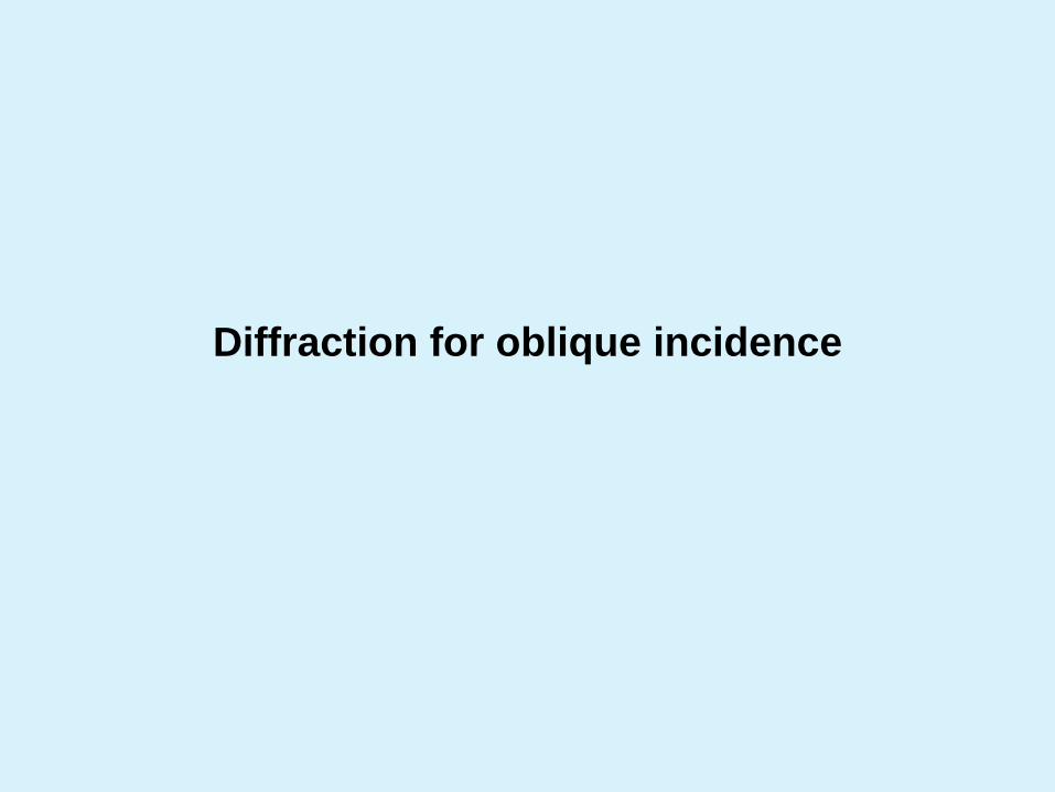
Diffraction for oblique incidence
For single slit diffraction we will change
to
i
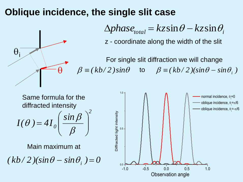
Oblique incidence, the single slit case
itotal kzkzphase sinsin
z - coordinate along the width of the slit
sin)2/kb( )sin)(sin2/kb( i
2
0
sinI4)(I
Same formula for the
diffracted intensity
0)sin)(sin2/kb( i
Main maximum at
-1.0 -0.5 0.0 0.5 1.00.0
0.5
1.0
Diffr
acte
d lig
ht in
tensity
Observation angle
normal incidence, i=0
oblique incidence, i=/6
oblique incidence, i=-/6

Oblique incidence, many slits
Phase shift between adjacent slits changes
from to sin)2/(ka )sin)(sin2/( ika
22
0sin
NsinsinI)(I
Same formula for the diffracted intensity
m)sin(sina im
Maxima are given by the condition:
Diffraction pattern using blazed
reflecting grooves
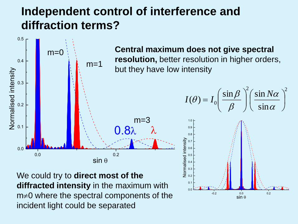
Independent control of interference and
diffraction terms?
0.0 0.2
0.0
0.1
0.2
0.3
0.4
0.5
No
rma
lise
d in
tensity
sin
0.8
m=0
m=3
m=1
We could try to direct most of the
diffracted intensity in the maximum with
m0 where the spectral components of the
incident light could be separated
Central maximum does not give spectral
resolution, better resolution in higher orders,
but they have low intensity
22
0sin
sinsin)(
NII
-0.2 0.0 0.2
0.0
0.1
0.2
0.3
0.4
0.5
0.6
0.7
0.8
0.9
1.0
Norm
alis
ed inte
nsity
sin

reflective
surface Blaze
angle i
i-2
a
Diffraction with blazed reflective grooves
)]sin()[sin(2
kbi
)sin)(sin2/ka( i
The “single-slit” diffraction maximum will be
determined by the specular direction and is
defined by the blaze angle
The phase difference from different “slits”
(grooves) is independent of the blaze angle
and is still determined by the direction of
incidence:
Introducing additional phase shifts using blazed
grooves gives us independent control of the
diffraction and interference terms

Spectroscopy with blazed grooves
0.0 0.2
0.0
0.1
0.2
0.3
0.4
0.5
No
rma
lise
d in
tensity
sin
0.0 0.1 0.2 0.3
0.0
0.1
0.2
0.3
0.4
0.5
0.6
0.7
0.8
0.9
1.0
Norm
alis
ed inte
nsity
sin
m=0
m=3
m=1
m=2
m=3
m=1
m=0
Using blazed grooves the signal in m0
maximum can be strongly enhanced
Graph shows
diffraction pattern for
i =0 and =/15
Note, for m=3 the two
peaks almost overlap.
We can introduce a
free spectral range:
λ/mΔλFSR

Diffraction grating
American astronomer David Rittenhouse invented the first man-made
diffraction grating in 1785. Fraunhofer also developed a diffraction grating in
1821, which occurred after James Gregory discovered the principles of
diffraction grating.

Diffraction grating
A repetitive array of diffracting elements (either apertures or obstacles) that
has the effect of producing periodic alterations in the phase, amplitude or
both, of an emergent wave is said to be a diffraction grating
Main application of diffraction gratings is for spectroscopy: to disperse
light with a mixture of wavelengths so that its intensity can be measured as
a function of wavelength
m)sin(sina im
Diffraction grating equation
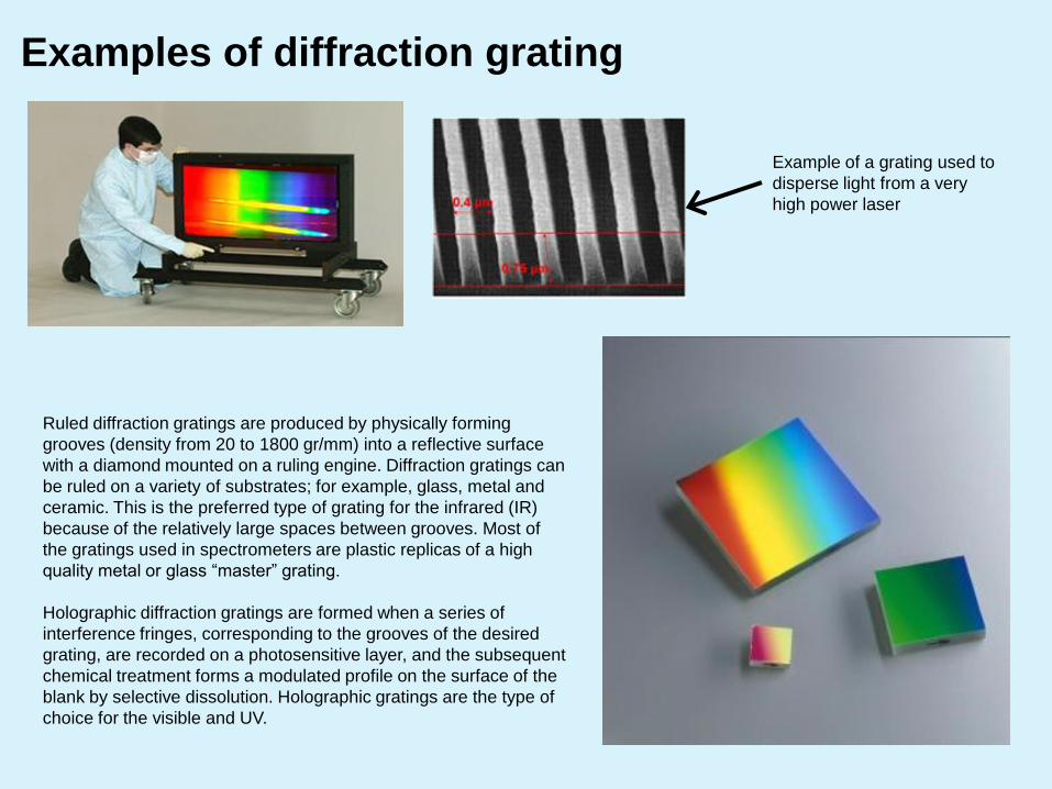
Ruled diffraction gratings are produced by physically forming
grooves (density from 20 to 1800 gr/mm) into a reflective surface
with a diamond mounted on a ruling engine. Diffraction gratings can
be ruled on a variety of substrates; for example, glass, metal and
ceramic. This is the preferred type of grating for the infrared (IR)
because of the relatively large spaces between grooves. Most of
the gratings used in spectrometers are plastic replicas of a high
quality metal or glass “master” grating.
Holographic diffraction gratings are formed when a series of
interference fringes, corresponding to the grooves of the desired
grating, are recorded on a photosensitive layer, and the subsequent
chemical treatment forms a modulated profile on the surface of the
blank by selective dissolution. Holographic gratings are the type of
choice for the visible and UV.
Examples of diffraction grating
Example of a grating used to
disperse light from a very
high power laser
Grating spectrometers
In 1814, Fraunhofer invented the spectroscope, and discovered 574
dark lines appearing in the solar spectrum. These were later shown to
be atomic absorption lines, as explained by Kirchhoff and Bunsen in
1859. These lines are still called Fraunhofer lines in his honour.
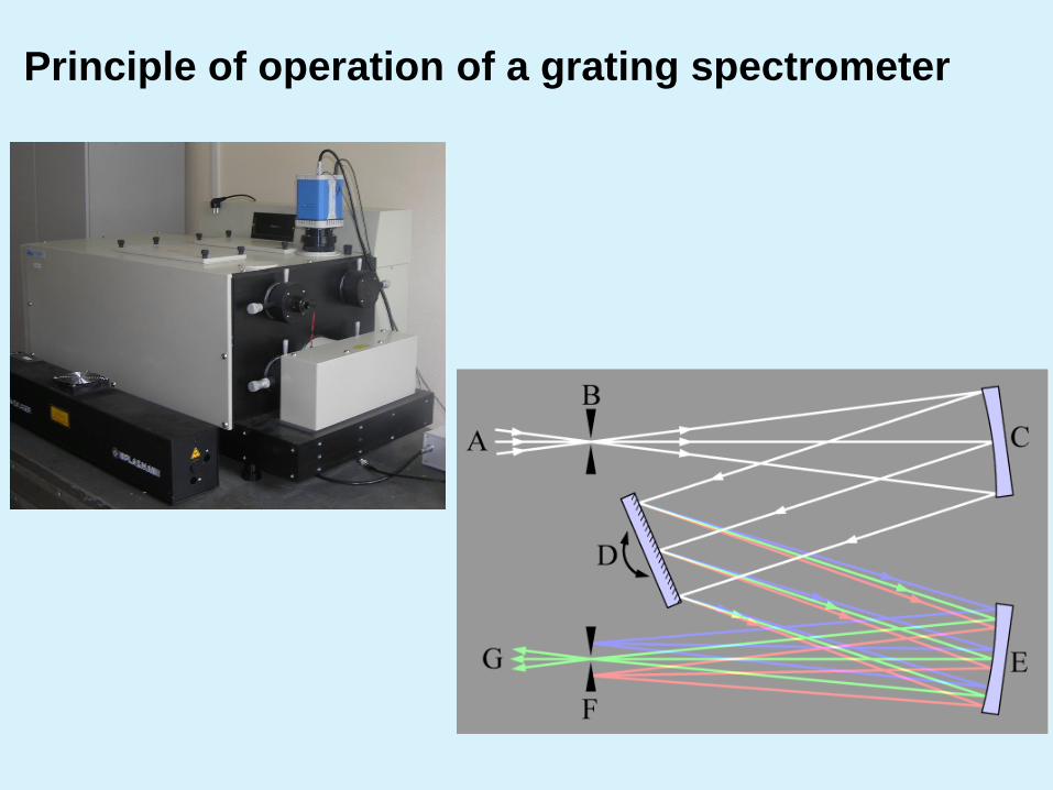
Principle of operation of a grating spectrometer

More examples and
applications can be found at:
www.oceanoptics.com/
www.jobinyvon.com/
www.princetoninstruments.com/
products/spec/actonseries/
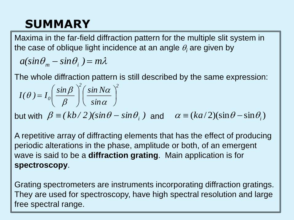
SUMMARY Maxima in the far-field diffraction pattern for the multiple slit system in
the case of oblique light incidence at an angle i are given by
The whole diffraction pattern is still described by the same expression:
but with and
A repetitive array of diffracting elements that has the effect of producing
periodic alterations in the phase, amplitude or both, of an emergent
wave is said to be a diffraction grating. Main application is for
spectroscopy.
Grating spectrometers are instruments incorporating diffraction gratings.
They are used for spectroscopy, have high spectral resolution and large
free spectral range.
m)sin(sina im
22
0sin
NsinsinI)(I
)sin)(sin2/kb( i )sin)(sin2/( ika
![[PPT]Diffraction gratings - Welcome | Biomedical Optics …bol.egr.uh.edu/.../bol/files/files/Diffraction_gratings.ppt · Web viewDiffraction gratings By M. Ravi Kiran Introduction](https://static.fdocuments.us/doc/165x107/5ac864db7f8b9a6b578c1399/pptdiffraction-gratings-welcome-biomedical-optics-bolegruhedubolfilesfilesdiffraction.jpg)