Lecture 14
36
Module6/Lesson3 1 Applied Elasticity for Engineers T.G.Sitharam & L.GovindaRaju Module 6: Two Dimensional Problems in Polar Coordinate System 6.3.1 BARS WITH LARGE INITIAL CURVATURE There are practical cases of bars, such as hooks, links and rings, etc. which have large initial curvature. In such a case, the dimensions of the cross-section are not very small in comparison with either the radius of curvature or with the length of the bar. The treatment that follows is based on the theory due to Winkler and Bach. 6.3.2 WINKLER’S – BACH THEORY Assumptions 1. Transverse sections which are plane before bending remain plane even after bending. 2. Longitudinal fibres of the bar, parallel to the central axis exert no pressure on each other. 3. All cross-sections possess a vertical axis of symmetry lying in the plane of the centroidal axis passing through C (Figure 6.11) 4. The beam is subjected to end couples M. The bending moment vector is normal throughout the plane of symmetry of the beam. Winkler-Bach Formula to Determine Bending Stress or Normal Stress (Also known as Circumferential Stress) Figure 6.11 Beam with large initial curvature (a) (b)
-
Upload
sreejith-menon -
Category
Documents
-
view
72 -
download
4
description
IISc B product
Transcript of Lecture 14

Module6/Lesson3
1 Applied Elasticity for Engineers T.G.Sitharam & L.GovindaRaju
Module 6: Two Dimensional Problems in Polar Coordinate System
6.3.1 BARS WITH LARGE INITIAL CURVATURE
There are practical cases of bars, such as hooks, links and rings, etc. which have large initial curvature. In such a case, the dimensions of the cross-section are not very small in comparison with either the radius of curvature or with the length of the bar. The treatment that follows is based on the theory due to Winkler and Bach.
6.3.2 WINKLER’S – BACH THEORY
Assumptions
1. Transverse sections which are plane before bending remain plane even after bending.
2. Longitudinal fibres of the bar, parallel to the central axis exert no pressure on each other.
3. All cross-sections possess a vertical axis of symmetry lying in the plane of the centroidal axis passing through C (Figure 6.11)
4. The beam is subjected to end couples M. The bending moment vector is normal throughout the plane of symmetry of the beam.
Winkler-Bach Formula to Determine Bending Stress or Normal Stress (Also known as Circumferential Stress)
Figure 6.11 Beam with large initial curvature
(a)
(b)

Module6/Lesson3
2 Applied Elasticity for Engineers T.G.Sitharam & L.GovindaRaju
Consider a curved beam of constant cross-section, subjected to pure bending produced by couples M applied at the ends. On the basis of plane sections remaining plane, we can state that the total deformation of a beam fiber obeys a linear law, as the beam element rotates through small angle Ddq. But the tangential strain eq does not follow a linear relationship.
The deformation of an arbitrary fiber, gh = ec Rdq + yDdq where ec denotes the strain of the centroidal fiber But the original length of the fiber gh = (R + y) dq
Therefore, the tangential strain in the fiber gh = eq = q
qqedyR
dyRdc
)(
][
+D+
Using Hooke’s Law, the tangential stress acting on area dA is given by
sq = ( ) EyR
ddyRc
+D+ )/( qqe
(6.61)
Let angular strain lqq
=Ddd
Hence, Equation (6.61) becomes
sq = ( ) EyR
yRc
++ le
(6.62)
Adding and subtracting ecy in the numerator of Equation (6.62), we get,
sq = ( ) EyR
yyyR ccc
+-++ eele
Simplifying, we get
sq = ( ) EyR
ycc ú
û
ùêë
é+
-+ )( ele (6.63a)
The beam section must satisfy the conditions of static equilibrium,
Fz = 0 and Mx = 0, respectively:
\ ò ò == MydAdA qq ss and0 (6.63b)
Substituting the above boundary conditions (6.63b) in (6.63a), we get
Module6/Lesson3
3 Applied Elasticity for Engineers T.G.Sitharam & L.GovindaRaju
0 = ( )ò úû
ùêë
é+
-+ dAyR
ycc )( ele
or ( )ò ò +--= dA
yRy
dA cc )( ele
or ( )ò ò +--= dA
yRy
dA cc )( ele (6.63c)
Also,
M = ( ) EdAyR
yydA cc ú
û
ùêë
é+
-+ò ò2
)( ele (6.63d)
Here ò = AdA , and since y is measured from the centroidal axis, ò = .0ydA
Let ( )ò -=+
mAdAyR
y
Or m = - ( )ò +dA
yRy
A1
Therefore, ( ) ( )ò ò ÷÷ø
öççè
æ+
-=+
dAyR
RyydA
yRy 2
= ( )ò ò +- dA
yRRy
ydA
= 0 – R [-mA]
\ ( )ò =+
mRAdAyR
y 2
Substituting the above values in (6.63c) and (6.63d), we get,
ec = (l - ec)m
and M = E (l-ec) mAR
From the above, we get
ec = AERM
and l ÷øö
çèæ +=
mRM
RM
AE1
(6.63e)
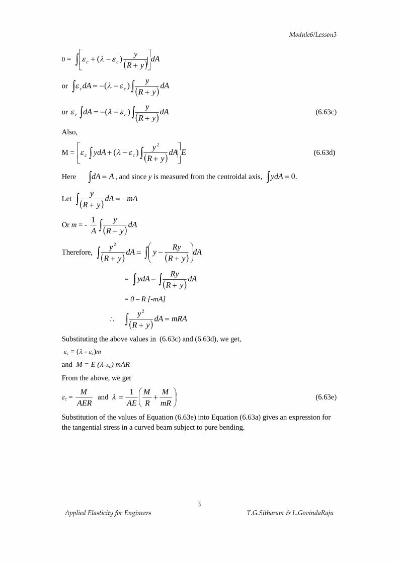
Substitution of the values of Equation (6.63e) into Equation (6.63a) gives an expression for the tangential stress in a curved beam subject to pure bending.
Module6/Lesson3
4 Applied Elasticity for Engineers T.G.Sitharam & L.GovindaRaju
Therefore, sq = úû
ùêë
é+
+)(
1yRm
yARM
(6.64)
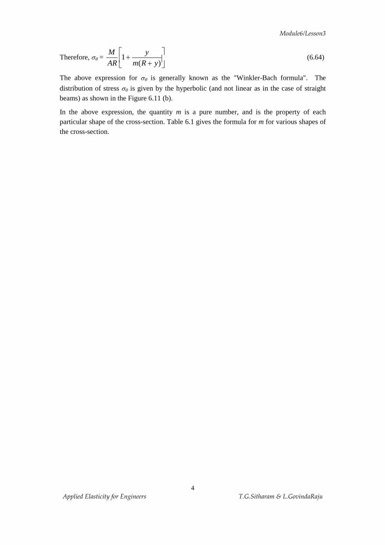
The above expression for sq is generally known as the "Winkler-Bach formula". The
distribution of stress sq is given by the hyperbolic (and not linear as in the case of straight beams) as shown in the Figure 6.11 (b).
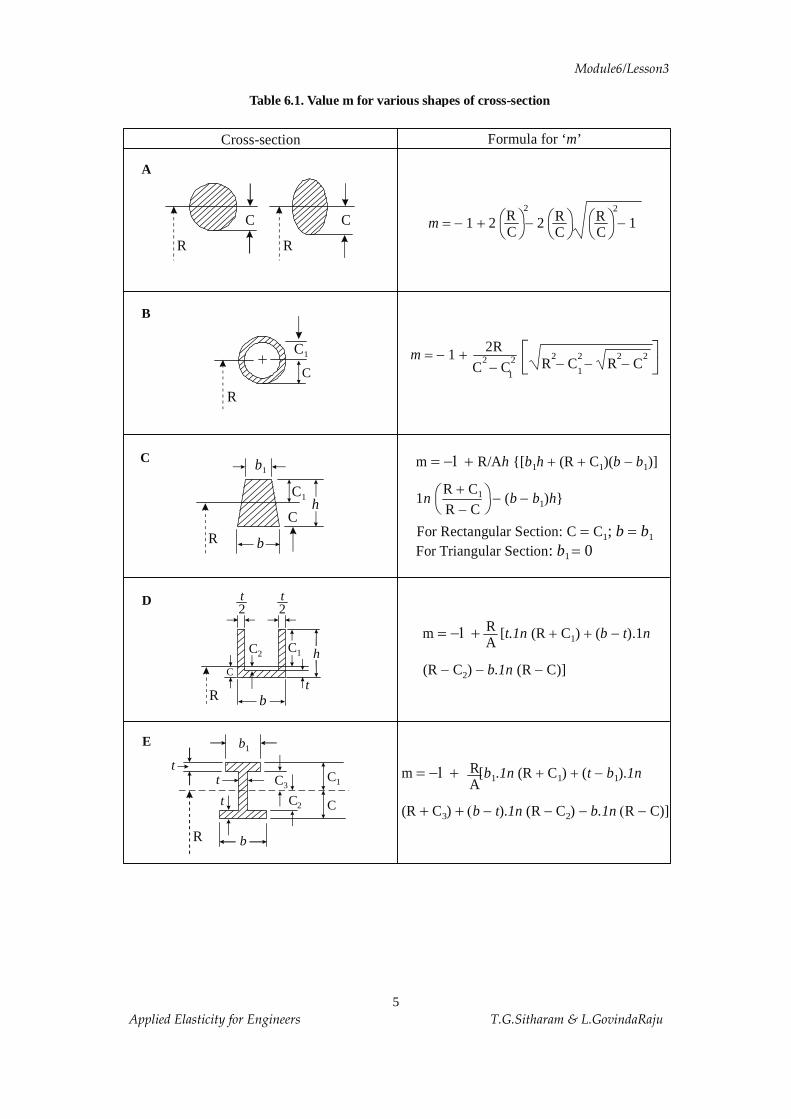
In the above expression, the quantity m is a pure number, and is the property of each particular shape of the cross-section. Table 6.1 gives the formula for m for various shapes of the cross-section.
Module6/Lesson3
5 Applied Elasticity for Engineers T.G.Sitharam & L.GovindaRaju
Table 6.1. Value m for various shapes of cross-section
Formula for ‘ ’m
m = -1 + [ (R C ) ( ).1
(R C ) (R C)]
t.1n b t n
b.1n
+ + -
- - -
1
2
RA
m = -1 +
+ +
[ (R C ) ( ).
(R C ) ). (R C ) R C)]
b .1n t b 1n
b t 1n b.1n
1 1 1
3 2
+ + -
( - - - ( -
RA
Cross-section
A
C
R
B
C
R
C1
D
bR
C2
C1C3
C
b1
t t
t
E
C
R b
h
b1
C1
C
C
R
t
h C 1
C
C 2
R
t2
b
t2
1 2 2 m = - + - - 1RC
R 2
C R
2
Cö ø
æ è
ö ø
æ è
ö ø
æ è
For Rectangular Section: ; = b bC C1 1=For Triangular Section: 0b1 =
m = -1 + R/A {[ (R C )( )]
1 ( ) }
h b h b b
n b b h
1 1 1
1
+ + -
- -
1 m = - +1
2R C C
2 2- R
2 2 2 2- - - C R C
1
éë
ù û
R CR C
+-
1ö ø
æ è
Module6/Lesson3
6 Applied Elasticity for Engineers T.G.Sitharam & L.GovindaRaju
Sign Convention
The following sign convention will be followed:
1. A bending moment M will be taken as positive when it is directed towards the concave side of the beam (or it decreases the radius of curvature), and negative if it increases the radius of curvature.
2. 'y' is positive when measured towards the convex side of the beam, and negative when measured towards the concave side (or towards the centre of curvature).
3. With the above sign convention, if sq is positive, it denotes tensile stress while negative sign means compressive stress.
The distance between the centroidal axis (y = 0) and the neutral axis is found by setting the tangential stress to zero in Equation (5.15)
\ 0 = úû
ùêë
é+
+)(
1yRm
yARM
or 1 = - )( n
n
yRm
y
-
where yn denotes the distance between axes as indicated in Figure 5.2. From the above,
yn = ( )1+-
mmR
This expression is valid for pure bending only. However, when the beam is acted upon by a normal load P acting through the centriod of cross-sectional area A, the tangential stress given by Equation (5.15) is added to the stress produced by this normal load P. Therefore, for this simple case of superposition, we have
sq = úû
ùêë
é+
++)(
1yRm
yARM
AP
(6.65)
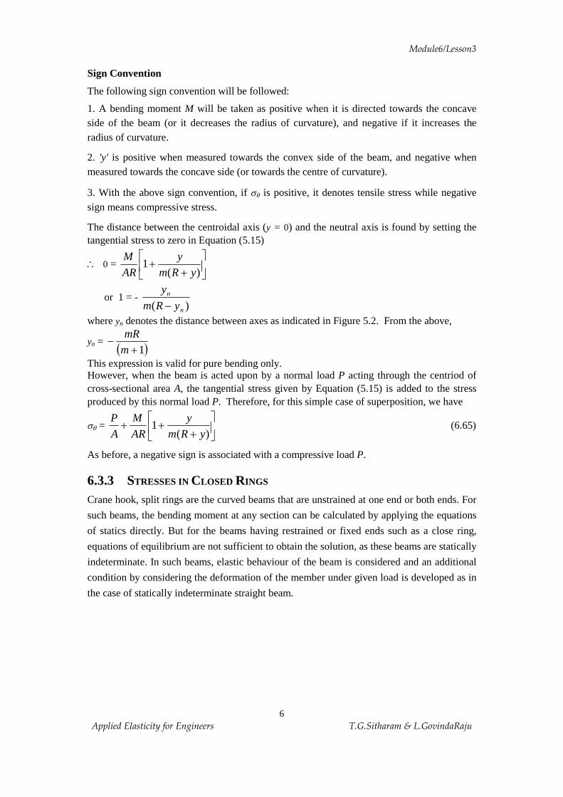
As before, a negative sign is associated with a compressive load P. 6.3.3 STRESSES IN CLOSED RINGS
Crane hook, split rings are the curved beams that are unstrained at one end or both ends. For
such beams, the bending moment at any section can be calculated by applying the equations
of statics directly. But for the beams having restrained or fixed ends such as a close ring,
equations of equilibrium are not sufficient to obtain the solution, as these beams are statically
indeterminate. In such beams, elastic behaviour of the beam is considered and an additional
condition by considering the deformation of the member under given load is developed as in
the case of statically indeterminate straight beam.

Module6/Lesson3
7 Applied Elasticity for Engineers T.G.Sitharam & L.GovindaRaju
Now, consider a closed ring shown in figure 6.12 (a), which is subjected to a concentrated load P along a vertical diametrical plane.
Figure 6.12 Closed ring subjected to loads
The distribution of stress in upper half of the ring will be same as that in the lower half due to the symmetry of the ring. Also, the stress distribution in any one quadrant will be same as in another. However, for the purposes of analysis, let us consider a quadrant of the circular ring as shown in the Figure 6.12 (c), which may be considered to be fixed at the section BB
(a) (b)
(c)
(d)

Module6/Lesson3
8 Applied Elasticity for Engineers T.G.Sitharam & L.GovindaRaju
and at section AA subjected to an axial load 2P
and bending moment AM . Here the
magnitude and the sign of the moment AM are unknown.
Now, taking the moments of the forces that lie to the one side of the section, then we get,
( )xRP
MM Amn -+-=2
But from Figure, qcosRx =
( )qcos2
RRP
MM Amn -+-=\
( )qcos12
-+-=\PR
MM Amn (a)
The moment mnM at the section MN cannot be determined unless the magnitude of AM is
known. Resolving 2P
into normal and tangential components, we get
Normal Component, producing uniform tensile stress = N = qcos21
P
Tangential component, producing shearing stress = qsin21
PT =

Module6/Lesson3
9 Applied Elasticity for Engineers T.G.Sitharam & L.GovindaRaju
Determination of AM
Figure 6.13 Section PQMN
Consider the elastic behavior of the two normal sections MN and PQ, a differential distance apart. Let the initial angle qd between the planes of these two sections change by an amount qdD when loads are applied.
Therefore, the angular strain = qqw
ddD
=
i.e., .qwq dd =D
Therefore, if we are interested in finding the total change in angle between the sections, that
makes an angle 1q and 2q with the section AA, the expression ò1
2
q
qqw d will give that angle.
But in the case of a ring, sections AA and BB remain at right angles to each other before and after loading. Thus, the change in the angle between these planes is equal to zero. Hence
ò =2 0p
qwo
d (b)
Module6/Lesson3
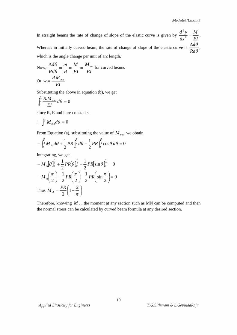
10 Applied Elasticity for Engineers T.G.Sitharam & L.GovindaRaju
In straight beams the rate of change of slope of the elastic curve is given by EIM
dxyd
=2
2
.
Whereas in initially curved beam, the rate of change of slope of the elastic curve is qq
RddD
,
which is the angle change per unit of arc length.
Now, EI
MEIM
RRdd mn===
D wqq
for curved beams
Or EI
MRw mn=
Substituting the above in equation (b), we get
ò =2 0.p
qo
mn dEIMR
since R, E and I are constants,
ò =\ 2 0p
qo mndM
From Equation (a), substituting the value of ,mnM we obtain
ò òò =-+- 2
0
2
0
2
00cos
21
21p pp
qqqq dPRdPRdM A
Integrating, we get
[ ] [ ] [ ] 0sin21
21 2
020
20 =-+-
ppp
qqq PRPRM A
02
sin21
221
2=÷
øö
çèæ-÷
øö
çèæ+÷
øö
çèæ-
pppPRPRM A
Thus ÷øö
çèæ -=
p2
12
PRM A
Therefore, knowing AM , the moment at any section such as MN can be computed and then the normal stress can be calculated by curved beam formula at any desired section.

Module6/Lesson3
11 Applied Elasticity for Engineers T.G.Sitharam & L.GovindaRaju
6.3.4 NUMERICAL EXAMPLES
Example 6.1 Given the following stress function
qqp
f cosrP
=
Determine the stress components qq tss rr and,
Solution: The stress components, by definition of f , are given as follows
2
2
2
11qffs
¶¶
÷øö
çèæ+
¶¶
÷øö
çèæ=
rrrr (i)
2
2
r¶¶
=fs q (ii)
qf
qft q ¶¶
¶÷øö
çèæ-
¶¶
÷øö
çèæ=
rrrr
2
2
11 (iii)
The various derivatives are as follows:
qqp
fcos
Pr
=¶¶
02
2
=¶¶
rf
( )qqqpq
fcossin +-=
¶¶
rP
( )qqqpq
fsin2cos
2
2
+-=¶¶
rP
( )qqqpq
fcossin
2
+-=¶¶
¶ Pr
Substituting the above values in equations (i), (ii) and (iii), we get
( )qqqp
qqp
s sin2cos1
cos1
2 +÷øö
çèæ-÷
øö
çèæ= r
Pr
Prr
qp
qqp
qqp
sin21
cos1
cos1 P
rP
rP
r÷øö
çèæ-÷
øö
çèæ-÷
øö
çèæ=
qp
s sin2 Prr -=\
02
2
=¶¶
=rfs q
Module6/Lesson3
12 Applied Elasticity for Engineers T.G.Sitharam & L.GovindaRaju
( ) ( )qqqp
qqqp
t q cossin1
cossin1
2 +-÷øö
çèæ-+-÷
øö
çèæ=
Pr
rP
rr
0=\ qt r
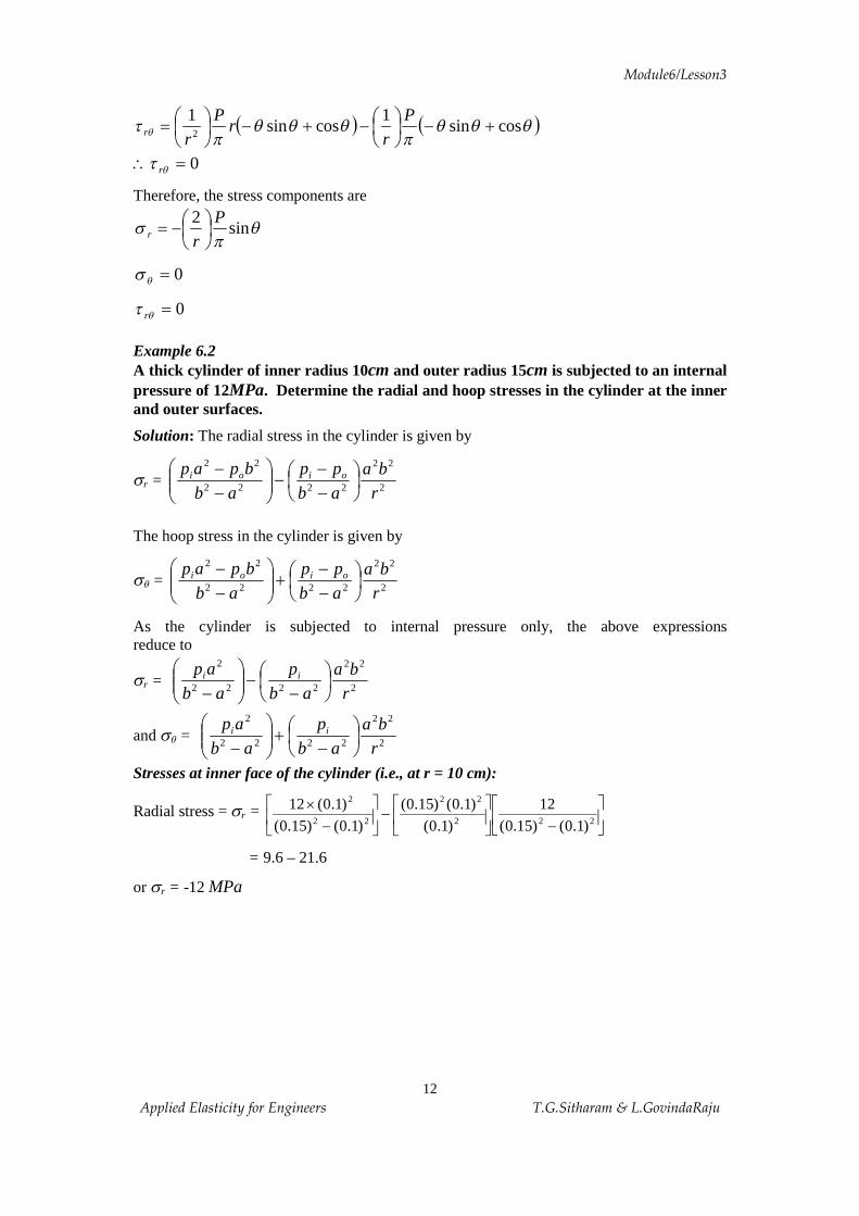
Therefore, the stress components are
qp
s sin2 Prr ÷
øö
çèæ-=
0=qs
0=qt r
Example 6.2 A thick cylinder of inner radius 10cm and outer radius 15cm is subjected to an internal pressure of 12MPa. Determine the radial and hoop stresses in the cylinder at the inner and outer surfaces.
Solution: The radial stress in the cylinder is given by
sr = 2
22
2222
22
rba
abpp
abbpap oioi ÷
øö
çèæ
--
-÷÷ø
öççè
æ--
The hoop stress in the cylinder is given by
sq = 2
22
2222
22
rba
abpp
abbpap oioi ÷
øö
çèæ
--
+÷÷ø
öççè
æ--
As the cylinder is subjected to internal pressure only, the above expressions reduce to
sr = 2
22
2222
2
rba
abp
abap ii ÷
øö
çèæ
--÷÷
ø
öççè
æ-
and sq = 2
22
2222
2
rba
abp
abap ii ÷
øö
çèæ
-+÷÷
ø
öççè
æ-
Stresses at inner face of the cylinder (i.e., at r = 10 cm):
Radial stress = sr = úû
ùêë
é-ú
û
ùêë
é-ú
û
ùêë
é-
´222
22
22
2
)1.0()15.0(12
)1.0()1.0()15.0(
)1.0()15.0()1.0(12
= 9.6 – 21.6
or sr = -12 MPa

Module6/Lesson3
13 Applied Elasticity for Engineers T.G.Sitharam & L.GovindaRaju
Hoop stress = sq = úû
ùêë
éúû
ùêë
é-
+úû
ùêë
é-
´2
22
2222
2
)1.0(
)1.0()15.0(
)1.0()15.0(
12
)1.0()15.0(
)1.0(12
= 9.6 + 21.6
or sq = 31.2 MPa
Stresses at outerface of the cylinder (i.e., at r = 15 cm):
Radial stress = sr = úû
ùêë
éúû
ùêë
é-
-úû
ùêë
é-
´2
22
2222
2
)15.0()15.0()1.0(
)1.0()15.0(12
)1.0()15.0()1.0(12
sr = 0
Hoop stress = sq = úû
ùêë
é
-úû
ùêë
é+ú
û
ùêë
é
-´
222
22
22
2
)1.0()15.0(
12
)15.0(
)15.0()1.0(
)1.0()15.0(
)1.0(12
= 9.6 + 9.6
or sq = 19.2 MPa Example 6.3 A steel tube, which has an outside diameter of 10cm and inside diameter of 5cm, is subjected to an internal pressure of 14 MPa and an external pressure of 5.5 MPa. Calculate the maximum hoop stress in the tube.
Solution: The maximum hoop stress occurs at r = a.
Therefore, Maximum hoop stress = (sq)max = úû
ùêë
éúûù
êëé
--
+úû
ùêë
é--
2
22
220
22
20
2
a
ba
ab
pp
ab
bpap ii
= 2220
22
20
2
bab
pp
ab
bpap iiúûù
êëé
--
+úû
ùêë
é--
= 22
20
220
2
ab
bpbpbpap ii
--+-
(sq)max = 22
20
22 2)(
ab
bpbapi
--+
Therefore, (sq)max = 2)05.0(2)1.0(
2)1.0(5.52]2)1.0(2)05.0[(14
-
´´-+
Or (sq)max = 8.67 MPa
Module6/Lesson3
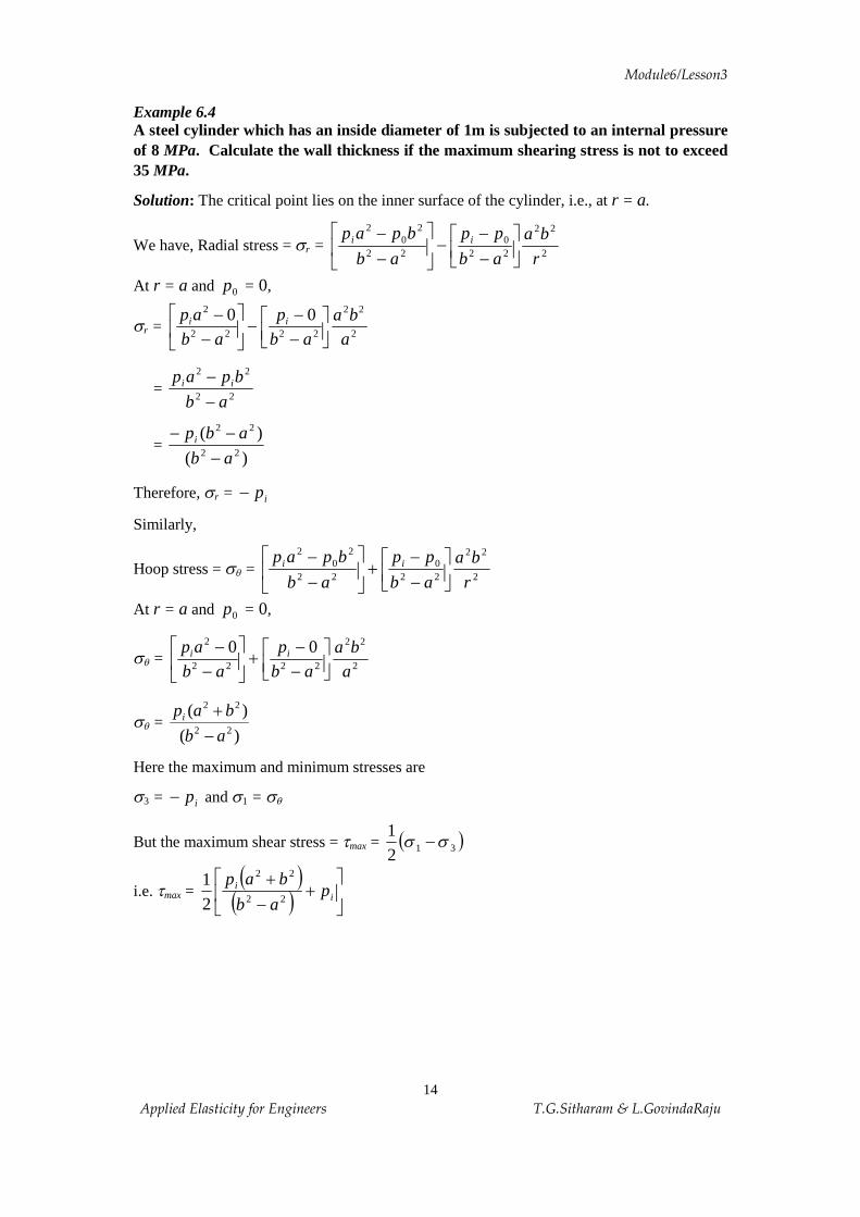
14 Applied Elasticity for Engineers T.G.Sitharam & L.GovindaRaju
Example 6.4 A steel cylinder which has an inside diameter of 1m is subjected to an internal pressure of 8 MPa. Calculate the wall thickness if the maximum shearing stress is not to exceed 35 MPa.
Solution: The critical point lies on the inner surface of the cylinder, i.e., at r = a.
We have, Radial stress = sr = 2
22
220
22
20
2
r
ba
ab
pp
ab
bpap iiúûù
êëé
--
-úû
ùêë
é--
At r = a and 0p = 0,
sr = 2
22
2222
2 00aba
abp
abap ii
úûù
êëé
--
-úû
ùêë
é-
-
= 22
22
ab
bpap ii
--
= )(
)(22
22
ab
abpi
---
Therefore, sr = ip-
Similarly,
Hoop stress = sq = 2
22
220
22
20
2
r
ba
ab
pp
ab
bpap iiúûù
êëé
--
+úû
ùêë
é--
At r = a and 0p = 0,
sq = 2
22
2222
2 00aba
abp
abap ii
úûù
êëé
--
+úû
ùêë
é-
-
sq = )(
)(22
22
ab
bapi
-+
Here the maximum and minimum stresses are
s3 = ip- and s1 = sq
But the maximum shear stress = tmax = ( )3121 ss -
i.e. tmax = ( )
( ) úû
ùêë
é+
-+
ii p
ab
bap22
22
21

Module6/Lesson3
15 Applied Elasticity for Engineers T.G.Sitharam & L.GovindaRaju
= ( ) úû
ùêë
é-
-++22
2222
21
ab
apbpbpap iiii
35 = )( 22
2
abbpi
-
i.e., 35 = )(
822
2
abb
-´
35b2-35a2 = 8b2
35b2-8b2 = 35a2
35b2-8b2 =35(0.5)2 Therefore, b = 0.5693
If t is the thickness of the cylinder, then b = 0.5+ t = 0.5693
\t = 0.0693 m or 69.3 mm. Example 6.5 The circular link shown in Figure 6.14 has a circular cross-section 3cm in diameter. The inside diameter of the ring is 4cm. The load P is 1000 kg. Calculate the stress at A and B. Compare the values with those found by the straight beam formula. Assume that the material is not stressed above its elastic strength.
Solution:
Cross-sectional area = A= 4p
(3)2 = 7.06 cm2.
For circular cross-section m is given by
m = -1+2
2
÷øö
çèæ
cR
–2 ÷øö
çèæ
cR
12
-÷øö
çèæ
cR
Here R = 2+1.5 = 3.5 cm
c = 1.5 cm. (Refer Table 6.1)
Therefore, Figure 6.14 Loaded circular link
m = 15.15.3
5.15.3
25.15.3
2122
-÷øö
çèæ
÷øö
çèæ-÷
øö
çèæ+-
m = 0.050
.. AB
P
R
Module6/Lesson3
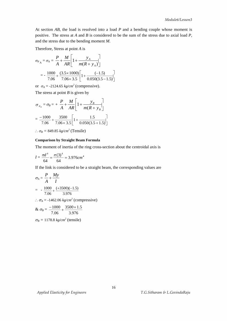
16 Applied Elasticity for Engineers T.G.Sitharam & L.GovindaRaju
At section AB, the load is resolved into a load P and a bending couple whose moment is positive. The stress at A and B is considered to be the sum of the stress due to axial load P, and the stress due to the bending moment M.
Therefore, Stress at point A is
sq A= sA = ú
û
ùêë
é+
++)(
1A
A
yRmy
ARM
AP
= - úû
ùêë
é-
-+
´´
+)5.15.3(050.0
)5.1(1
5.306.7)10005.3(
06.71000
or sA = -2124.65 kg/cm2 (compressive).
The stress at point B is given by
Bqs = sB = + úû
ùêë
é+
++B
B
yRmy
ARM
AP
(1
= úû
ùêë
é+
+´
+-
)5.15.3(050.05.1
15.306.7
350006.7
1000
\sB = 849.85 kg/cm2 (Tensile)
Comparison by Straight Beam Formula
The moment of inertia of the ring cross-section about the centroidal axis is
I = 444
976.364
)3(64
cmd
==pp
If the link is considered to be a straight beam, the corresponding values are
sA = I
MyAP
+
= - 976.3
)5.1)(3500(06.7
1000 -++
\sA = -1462.06 kg/cm2 (compressive)
& sB = 976.3
5.1350006.7
1000 ´+
-
sB = 1178.8 kg/cm2 (tensile)

Module6/Lesson3
17 Applied Elasticity for Engineers T.G.Sitharam & L.GovindaRaju
Figure 6.15 Stresses along the cross-section
Example 6.6
An open ring having T-Section as shown in the Figure 6.16 is subjected to a compressive load of 10,000 kg. Compute the stresses at A and B by curved beam formula.
Figure 6.16 Loaded open ring
1178.8
849.85
Straight beam
Curved beam
1462.06
2124.65
+
-
.
.
Centroid axis Neutral axis
A
B
d
10cm.. AB
18cm
P=10,000Kg
10.34cm
R
14cm
2cm
2cm
.
Module6/Lesson3
18 Applied Elasticity for Engineers T.G.Sitharam & L.GovindaRaju
Solution:
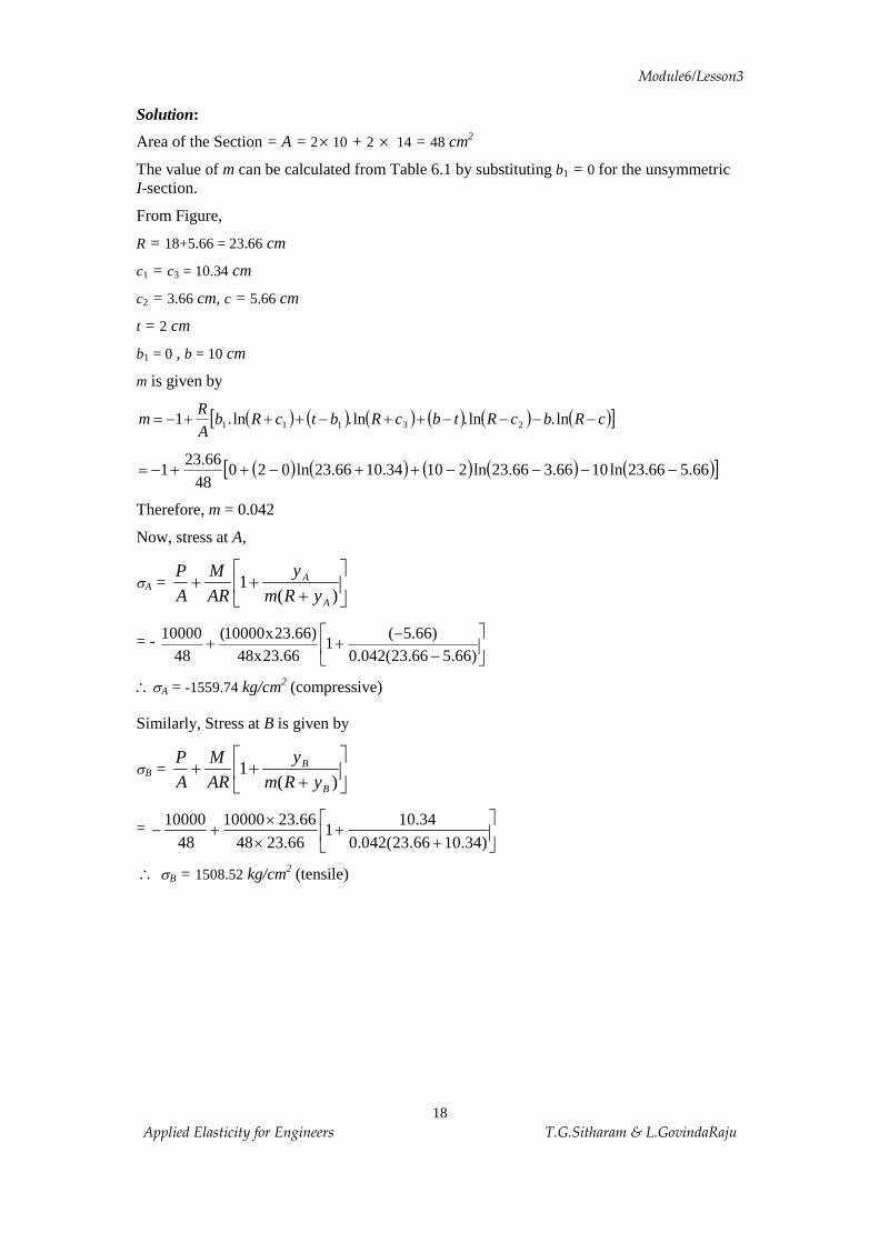
Area of the Section = A = 2 ´ 10 + 2 ´ 14 = 48 cm2
The value of m can be calculated from Table 6.1 by substituting b1 = 0 for the unsymmetric I-section.
From Figure,
R = 18+5.66 = 23.66 cm
c1 = c3 = 10.34 cm
c2 = 3.66 cm, c = 5.66 cm
t = 2 cm
b1 = 0 , b = 10 cm
m is given by
( ) ( ) ( ) ( ) ( ) ( )[ ]cRbcRtbcRbtcRbAR
m ----++-+++-= ln.ln.ln.ln.1 23111
( ) ( ) ( ) ( ) ( )[ ]66.566.23ln1066.366.23ln21034.1066.23ln02048
66.231 ----++-++-=
Therefore, m = 0.042
Now, stress at A,
sA = úû
ùêë
é+
++)(
1A
A
yRmy
ARM
AP
= - úû
ùêë
é-
-++
)66.566.23(042.0)66.5(
166.23x48
)66.23x10000(48
10000
\sA = -1559.74 kg/cm2 (compressive)
Similarly, Stress at B is given by
sB = úû
ùêë
é+
++)(
1B
B
yRmy
ARM
AP
= úû
ùêë
é+
+´
´+-
)34.1066.23(042.034.10
166.2348
66.231000048
10000
\ sB = 1508.52 kg/cm2 (tensile)
Module6/Lesson3
19 Applied Elasticity for Engineers T.G.Sitharam & L.GovindaRaju
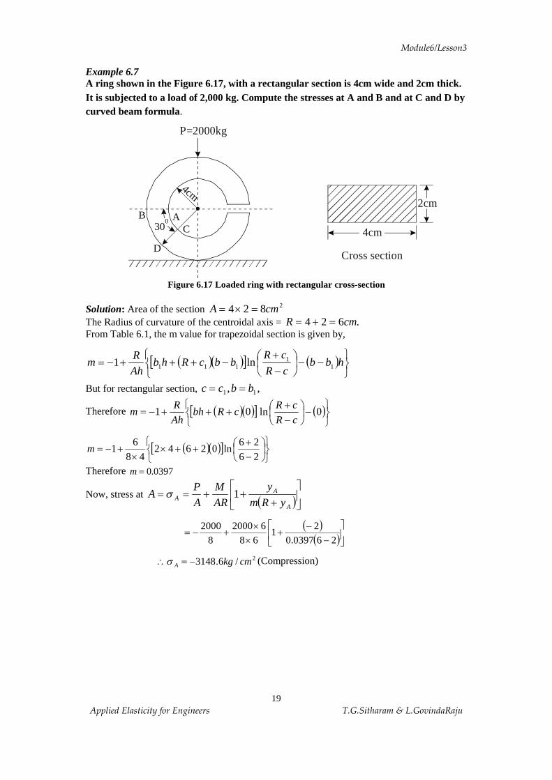
Example 6.7 A ring shown in the Figure 6.17, with a rectangular section is 4cm wide and 2cm thick. It is subjected to a load of 2,000 kg. Compute the stresses at A and B and at C and D by curved beam formula.
Figure 6.17 Loaded ring with rectangular cross-section
Solution: Area of the section 2824 cmA =´= The Radius of curvature of the centroidal axis = .624 cmR =+= From Table 6.1, the m value for trapezoidal section is given by,
( )( )[ ] ( )þýü
îíì
--÷øö
çèæ
-+
-+++-= hbbcR
cRbbcRhb
AhR
m 11
111 ln1
But for rectangular section, ,, 11 bbcc ==
Therefore ( )( )[ ] ( )þýü
îíì
-÷øö
çèæ
-+
+++-= 0ln01cRcR
cRbhAhR
m
( )( )[ ]þýü
îíì
÷øö
çèæ
-+
++´´
+-=2626
ln0264248
61m
Therefore 0397.0=m
Now, stress at ( )úûù
êë
é+
++==A
AA yRm
y
ARM
AP
A 1s
( )( )úû
ùêë
é-
-+
´´
+-=260397.0
21
6862000
82000
2/6.3148 cmkgA -=\s (Compression)
P=2000kg
.30
0 AC
B
D
4cm
4cm
2cm
Cross section
Module6/Lesson3
20 Applied Elasticity for Engineers T.G.Sitharam & L.GovindaRaju
Stress at ( )úûù
êë
é+
++==B
BB yRm
y
ARM
AP
B 1s
( )úûù
êë
é+
+´
´+
-=
260397.02
168
620008
2000
Therefore, 2/31.1574 cmkgB +=s (Tension)
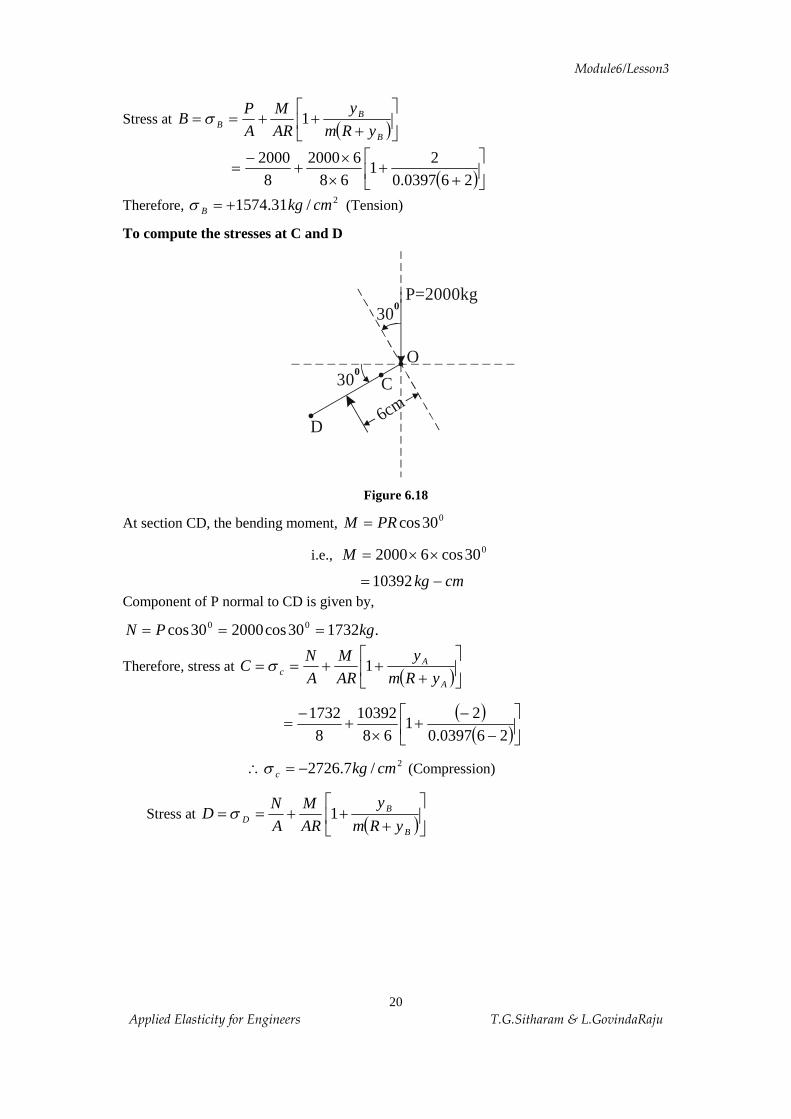
To compute the stresses at C and D
Figure 6.18
At section CD, the bending moment, 030cosPRM =
i.e., 030cos62000 ´´=M
cmkg -= 10392 Component of P normal to CD is given by,
.173230cos200030cos 00 kgPN ===
Therefore, stress at ( )úûù
êë
é+
++==A
Ac yRm
y
ARM
AN
C 1s
( )
( )úûù
êë
é-
-+
´+
-=
260397.02
168
103928
1732
2/7.2726 cmkgc -=\s (Compression)
Stress at ( )úûù
êë
é+
++==B
BD yRm
y
ARM
AN
D 1s
. .
O . 6cm
300
300
C
D
P=2000kg
Module6/Lesson3
21 Applied Elasticity for Engineers T.G.Sitharam & L.GovindaRaju
( )úûù
êë
é+
+´
+-
=260397.0
21
6810392
81732
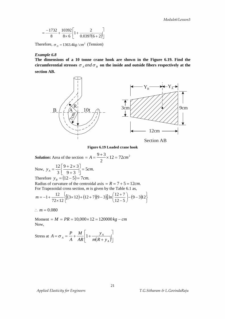
Therefore, 2/4.1363 cmkgD =s (Tension) Example 6.8 The dimensions of a 10 tonne crane hook are shown in the Figure 6.19. Find the circumferential stresses BA and ss on the inside and outside fibers respectively at the
section AB.
Figure 6.19 Loaded crane hook
Solution: Area of the section 272122
39cmA =´
+==
Now, .539
3293
12cmyA =úû
ùêëé
+´+
=
Therefore ( ) .7512 cmyB =-= Radius of curvature of the centroidal axis .1257 cmR =+== For Trapezoidal cross section, m is given by the Table 6.1 as,
( ) ( )( )[ ] ( )þýü
îíì
--÷øö
çèæ
-+
-++´´
+-= 1239512712
ln.397121231272
121m
080.0=\m
Moment cmkgPRM -=´=== 12000012000,10 Now,
Stress at ( )úûù
êë
é+
++==A
AA yRm
y
ARM
AP
A 1s
7cm
10tA R
B .
12cm
9cm3cm
Y B
Section AB
Y A
Module6/Lesson3
22 Applied Elasticity for Engineers T.G.Sitharam & L.GovindaRaju
( )( )úû
ùêë
é-
-+
´+
-=
51208.05
11272
12000072
10000
2/1240 cmkgA -=\s (Compression)
Stress at ( )úûù
êë
é+
++==B
BB yRm
yARM
AP
B 1s
( )úûù
êë
é+
+´
+-
=71208.0
71
1272120000
72000,10
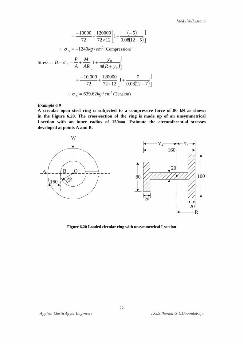
2/62.639 cmkgB =\s (Tension) Example 6.9 A circular open steel ring is subjected to a compressive force of 80 kN as shown in the Figure 6.20. The cross-section of the ring is made up of an unsymmetrical I-section with an inner radius of 150mm. Estimate the circumferential stresses developed at points A and B.
Figure 6.20 Loaded circular ring with unsymmetrical I-section
.A B O
150
W
160 . 80 100
160YBYA
20
20
20R

Module6/Lesson3
23 Applied Elasticity for Engineers T.G.Sitharam & L.GovindaRaju
Solution:
From the Table 6.1, the value of m for the above section is given by
( ) ( ) ( ) ( ) ( ) ( )[ ]cRbcRtbcRbtcRbAR
m ----++-+++-= lnlnlnln1 23111
Hence =R Radius of curvature of the centroidal axis.
Now, 2600020802012010020 mmA =´+´+´=
( ) ( ) ( ).33.75
6000150208080201201020100
mmyB =´´+´´+´´
=
( ) .67.8433.75160 mmyA =-=\
Also, ( ) .33.22533.75150 mmR =+=
( ) ( ) ( )( ) ( ) ( )úû
ùêë
é----
++-+++-=\
33.7533.225ln10033.5533.225ln20100
67.6433.225ln802067.8433.225ln80
600033.225
1m
.072.0=\m
Moment = .10803.133.225100080 7 mmNPRM -´=´´==
Now, Stress at point ( )úûù
êë
é+
++==B
BB yRm
y
ARM
AP
B 1s
( )( )úû
ùêë
é-
-+
´´
+-=\33.7533.225072.0
33.751
33.225600010803.1
600080000 7
Bs
2/02.93 mmNB -=\s (Compression)
Stress at point ( )úûù
êë
é+
++==A
AA yRm
y
ARM
AP
A 1s
( )úûù
êë
é+
+´
´+-=
67.8433.225072.067.84
133.2256000
10803.16000
80000 7
2/6.50 mmNA =\s (Tension)
Hence, the resultant stresses at A and B are, 2/6.50 mmNA =s (Tension), 2/02.93 mmNB -=s (Compression)

Module6/Lesson3
24 Applied Elasticity for Engineers T.G.Sitharam & L.GovindaRaju
Example 6.10 Calculate the circumferential stress on inside and outside fibre of the ring at A and B, shown in Figure 6.21. The mean diameter of the ring is 5cm and cross-section is circular with 2cm diameter. Loading is within elastic limit.
Figure 6.21 Loaded closed ring
Solution: For circular section, from Table 6.1
122122
-÷øö
çèæ
÷øö
çèæ-÷
øö
çèæ+-=
cR
cR
cR
m
115.2
15.2
215.2
2122
-÷øö
çèæ
÷øö
çèæ-÷
øö
çèæ+-=
0435.0=\m
We have, ÷øö
çèæ -=
p2
1PRM A
PR364.0= P5.2364.0 ´=
PM A 91.0=\
Now, ( )úûù
êë
é+
++÷øö
çèæ-=
A
iAA yRm
yARM
AP
i1s
( )
( )úûù
êë
é-
-+
´+÷
øö
çèæ-=
15.20435.01
15.2
91.0A
PAP
÷øö
çèæ-÷
øö
çèæ-=
AP
AP
21.5
. R=2.5c
mBi
AO
BO
Ai
2P 1000kg=
MA
m
n
q
P
Pcosq
Psinq
Ai AoP

Module6/Lesson3
25 Applied Elasticity for Engineers T.G.Sitharam & L.GovindaRaju
÷øö
çèæ-=\
AP
iA 21.6s (Compressive)
( )úûù
êë
é+
++÷øö
çèæ-=
B
oA yRm
yARM
AP
10
s
( )úûù
êë
é+
+´
+÷øö
çèæ-=
15.20435.01
15.2
91.0A
PAP
÷øö
çèæ=\
AP
oA 755.1s (Tension)
Similarly, ( )PRMM AB -=
( )PRPR -= 364.0 PR636.0-=
P5.2636.0 ´-=
PM B 59.1-=\
Now, ( )úûù
êë
é+
+=i
iBBi yRm
yARM
1s
( )
( )úûù
êë
é-
-+
´-=
15.20435.01
15.2
59.1A
P
÷øö
çèæ=\
AP
Bi 11.9s (Tension)
and ( )
( )úûù
êë
é+
++÷
øö
çèæ
´-=
15.20435.01
15.2
59.1A
PBos
÷øö
çèæ-=
AP
81.4 (Compression)
Now, substituting the values of ,500kgP =
( ) ,14159.31 22 cmA == p above stresses can be calculated as below.
2/988500
21.6 cmkgiA -=´-=
ps
2/32.279500
755.10
cmkgA =´=p
s
2/1450500
11.9 cmkgiB =´=
ps
2/54.765500
81.40
cmkgB -=´-=p
s
Module6/Lesson3
26 Applied Elasticity for Engineers T.G.Sitharam & L.GovindaRaju
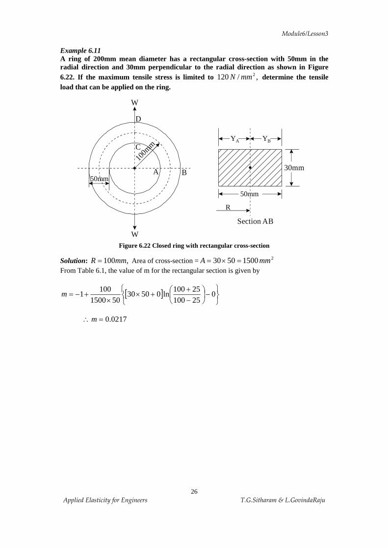
Example 6.11 A ring of 200mm mean diameter has a rectangular cross-section with 50mm in the radial direction and 30mm perpendicular to the radial direction as shown in Figure 6.22. If the maximum tensile stress is limited to ,/120 2mmN determine the tensile load that can be applied on the ring.
Figure 6.22 Closed ring with rectangular cross-section
Solution: ,100mmR = Area of cross-section = 215005030 mmA =´= From Table 6.1, the value of m for the rectangular section is given by
[ ]þýü
îíì
-÷øö
çèæ
-+
+´´
+-= 02510025100
ln05030501500
1001m
0217.0=\m
.
W
C
A
100m
m
B
W
D
50mm
.50mm
YA YB
30mm
R
Section AB
Module6/Lesson3
27 Applied Elasticity for Engineers T.G.Sitharam & L.GovindaRaju
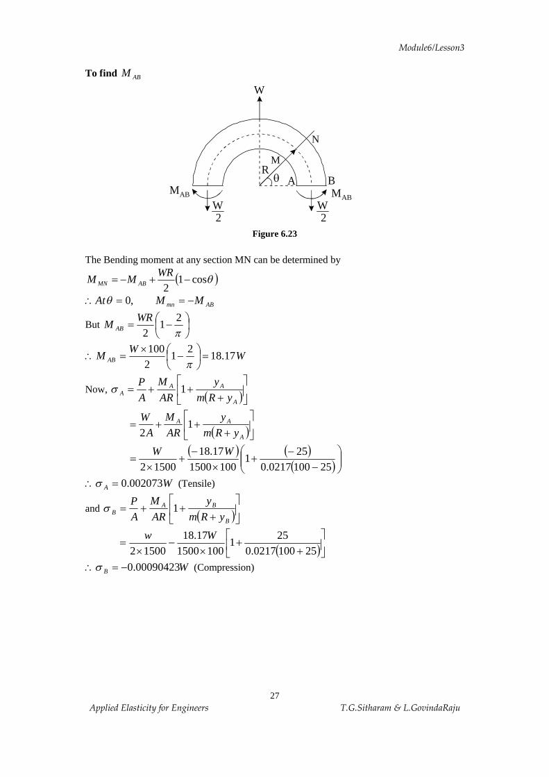
To find ABM
Figure 6.23
The Bending moment at any section MN can be determined by
( )qcos12
-+-=WR
MM ABMN
ABmn MMAt -==\ ,0q
But ÷øö
çèæ -=
p2
12
WRM AB
WW
M AB 17.182
12100
=÷øö
çèæ -
´=\
p
Now, ( )úûù
êë
é+
++=A
AAA yRm
y
AR
M
AP
1s
( )úûù
êë
é+
++=A
AA
yRmy
ARM
AW
12
( ) ( )
( )÷÷ø
öççè
æ-
-+
´-
+´
=251000217.0
251
100150017.18
15002WW
WA 002073.0=\s (Tensile)
and ( )úûù
êë
é+
++=B
BAB yRm
y
AR
M
AP
1s
( )úûù
êë
é+
+´
-´
=251000217.0
251
100150017.18
15002Ww
WB 00090423.0-=\s (Compression)
W
A B
W2
W2
R M
N
qMAB
MAB

Module6/Lesson3
28 Applied Elasticity for Engineers T.G.Sitharam & L.GovindaRaju
To find stresses at C and D
We have, ( )qcos12
-+-=WR
MM ABmn
2,900 WR
MMMAt ABCDmn +-===\ q
WWWM CD 83.312
10017.18 =´+-=\
Now, stress at ( )úûù
êë
é+
++==C
CCDC yRm
y
AR
M
AP
C 1s
( )
( )úûù
êë
é-
-+
´+=
251000217.025
11001500
83.310
W
W00305.0-= (Compression)
and stress at ( )úûù
êë
é+
++==D
DCDD yRm
y
AR
M
AP
D 1s
( )úûù
êë
é+
+´
+=251000217.0
251
100150083.31
0W
WD 00217.0=\s (Tensile) By comparison, the tensile stress is maximum at Point D.
12000217.0 =\ W kNorNW 3.5554.55299=\ Example 6.12 A ring of mean diameter 100mm is made of mild steel with 25mm diameter. The ring is subjected to four pulls in two directions at right angles to each other passing through the center of the ring. Determine the maximum value of the pulls if the tensile stress should not exceed 2/80 mmN
Module6/Lesson3
29 Applied Elasticity for Engineers T.G.Sitharam & L.GovindaRaju
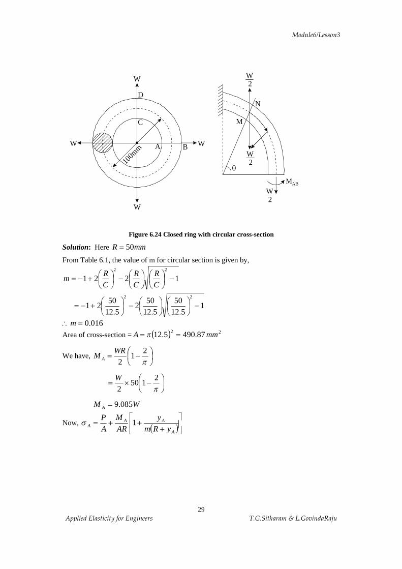
Figure 6.24 Closed ring with circular cross-section
Solution: Here mmR 50=
From Table 6.1, the value of m for circular section is given by,
122122
-÷øö
çèæ
÷øö
çèæ-÷
øö
çèæ+-=
CR
CR
CR
m
15.12
505.12
502
5.1250
2122
-÷øö
çèæ
÷øö
çèæ-÷
øö
çèæ+-=
016.0=\m
Area of cross-section = ( ) 22 87.4905.12 mmA == p
We have, ÷øö
çèæ -=
p2
12
WRM A
÷øö
çèæ -´=
p2
1502
W
WM A 085.9=
Now, ( )úûù
êë
é+
++=A
AAA yRm
yARM
AP
1s
.
W
C
A
100m
m B WW
W
D
MAB
M
N
q
W2
W2
W2

Module6/Lesson3
30 Applied Elasticity for Engineers T.G.Sitharam & L.GovindaRaju
( )
( )úûù
êë
é-
-+
´-
´=
5.1250016.05.12
15087.490
085.987.4902
WW
W0084.0= (Tensile)
( )úûù
êë
é+
+÷øö
çèæ
-+=\
B
BAB yRm
y
AR
M
AP
1s
( )úûù
êë
é+
+´
-´
=5.1250016.0
5.121
5087.490085.9
87.4902WW
WB 00398.0-=\s (Compression)
Also, ( ) ÷øö
çèæ ´+-=-= 50
2085.9
WPRMM ACD
WM CD 915.15+=\
Now, ( )úûù
êë
é-
+=C
CCDC yRm
y
AR
M1s
( )
( )úûù
êë
é-
-+
´+=
5.1250016.05.12
15087.490
918.15 W
WC 013.0-=\s (Compression)
and ( )úûù
êë
é+
+´
+=5.1250016.0
5.121
5087.490918.15 W
Ds
W0088.0= (Tension)
Stresses at Section CD due to horizontal Loads
We have, moment at any section MN is given by
( )qcos12
-+-=PR
MM AMN
At section CD, ,0=q
( )0cos12
-+-=\ RW
MM ACD
WMM ACD 085.9-=-=
Module6/Lesson3
31 Applied Elasticity for Engineers T.G.Sitharam & L.GovindaRaju
( )úûù
êë
é+
++=\C
CCDC yRm
y
AR
M
AP
1s
( ) ( )
( )úûù
êë
é-
-+
´-
+´
=5.1250016.0
5.121
5087.490085.9
87.4902WW
WC 00836.0=\s (Tensile)
and ( )úûù
êë
é+
++=D
DCDD yRm
y
AR
M
AP
1s
( )
( )úûù
êë
é+
+´
-+
´=
5.1250016.05.12
15087.490
085.987.4902
WW
WD 00398.0-=\s (Compression)
Resultant stresses are ( ) WWWC 00464.000836.0013.0 -=+-=s (Compression)
( ) WWWD 00482.000398.00088.0 =-=s (Tension)
In order to limit the tensile stress to 2/80 mmN in the ring, the maximum value of the force in the pulls is given by
0.00482W = 80
kNorNW 598.1651.16597=\ 6.3.5 EXERCISES
1. Is the following function a stress function?
qqp
f sinrP
÷øö
çèæ-=
If so, find the corresponding stress. What is the problem solved by this function? 2. Investigate what problem of plane stress is solved by the following stress
functions
(a) qqf sinrKP
=
(b) qqp
f sinrP
-=
3. Derive the equilibrium equation for a polar co-ordinate system. 4. Derive the expressions for strain components in polar co-ordinates.

Module6/Lesson3
32 Applied Elasticity for Engineers T.G.Sitharam & L.GovindaRaju
5. Starting from the stress function DCrrBrrA 22 loglog ++=f , obtain the stress
components rs and qs in a pipe subjected to internal pressure ip and external pressure
op . Obtain the maximum value of qs when 0=op and indicate where it occurs.
6. Check whether the following is a stress function ( )[ ]aqqaf tancos2222 rrrc -+-= where a is a constant.
7. Starting from the stress function 321
8)3(
rCr
CC rr +
+-+=
mf , derive expressions for
rs and qs in case of a rotating disk of inner radius 'a' and outer radius 'b'. Obtain the
maximum values of rs and qs .
8. Show that the stress function DCrrBrrA +++= 22 loglogf solves the problem of
axisymmetric stress distribution, obtain expressions for rs and qs in case of a pipe
subjected to internal pressure ir and external pressure 0r .
9. Show that the following stress function solves the problem of axisymmetric stress distribution in polar coordinates
DCrrBrrA +++= 22 loglogf 10. Explain axisymmetric problems with examples. 11. Derive the general expression for the stress function in the case of axisymmetric stress distribution. 12. Derive the expression for radial and tangential stress in a thick cylinder subjected to internal and external fluid pressure. 13. A curved bar bent into a arc of a circle having internal radius ‘a’ and external radius ‘b’ is subjected to a bending couple M at its end. Determine the stresses qss ,r and qt r .
14. For the stress function, rAr log2=f , where A is a constant, compute the stress
components qss ,r and qt r .
15. A thick cylinder of inner radius 150mm and outer radius 200mm is subjected to an
internal pressure of 15MN/m2. Determine the radial and hoop stresses in the cylinder at inner and outer surfaces. 16. The internal and external diameters of a thick hollow cylinder are 80mm and 120mm
respectively. It is subjected to an external pressure of 40MN/m2, when the internal
pressure is 120MN/m2. Calculate the circumferential stresses at the external and internal surfaces and determine the radial and circumferential stresses at the mean radius.
17. A thick-wall cylinder is made of steel (E = 200GPa and 29.0=n ), has an inside diameter of 20mm, and an outside diameter of 100mm. The cylinder is subjected to an

Module6/Lesson3
33 Applied Elasticity for Engineers T.G.Sitharam & L.GovindaRaju
internal pressure of 300MPa. Determine the stress components rs and qs at
r = a = 10mm, r = 25mm and r = b = 50mm. 18. A long closed cylinder has an internal radius of 100mm and an external radius of 250mm. It is subjected to an internal pressure of 80MPa. Determine the maximum radial, circumferential and axial stresses in the cylinder. 19. A solid disc of radius 200mm is rotating at a speed of 3000 rpm. Determine the radial and
hoop stresses in the disc if 3.0=n and r = 8000kg/m3. Also determine the stresses in
the disc if a hole of 30mm is bored at the centre of the disc.
20. A disc of 250mm diameter has a central hole of 50mm diameter and runs at 4000rpm.
Calculate the hoop stresses. Take 25.0=n and r = 7800 kg/m3.
21. A turbine rotor 400mm external diameter and 200mm internal diameter revolves at 1000rpm. Find the maximum hoop and radial stresses assuming the rotor to be thin disc.
Take the weight of the rotor as 7700 kg/m3 and poisson’s ratio 0.3. 22. Investigate what problem of plane stress is solved by the following stress function
22
3
2343
yP
C
xyxy
CF
+þýü
îíì
-=f . Check whether the following is a stress function
qf 2cos2
22 ÷øö
çèæ +++= D
rC
BrAr
23. Show that [ ] xDyeCyeBeAe yyyy aaaaa sin-- +++ represents stress function. 24. The curved beam shown in figure has a circular cross-section 50mm in diameter. The inside diameter of the curved beam is 40mm. Determine the stress at B when kNP 20= .
Figure 6.25
25. A crane hook carries a load kNW 20= as shown in figure. The cross-section mn of the hook is trapezoidal as shown in the figure. Find the total stresses at points m and n. Use
the data as given mmammbmmb 30,10,40 21 === and mmc 120=
B
P
C

Module6/Lesson3
34 Applied Elasticity for Engineers T.G.Sitharam & L.GovindaRaju
Figure 6.26
26. A semicircular curved bar is loaded as shown in figure and has a trapezoidal cross- section. Calculate the tensile stress at point A if kNP 5=
Figure 6.27
27. A curved beam with a circular centerline has a T-section shown in figure below. It is subjected to pure bending in its plane of symmetry. The radius of curvature of the concave face is 60mm. All dimensions of the cross-section are fixed as shown except the thickness t of the stem. Find the proper value of the stem thickness so that the extreme fiber stresses are bending will be numerically equal.
20mm
40mm A B
P
P
20mm
A B
20mm
20mm
20mm
W
ab2 b1
c
m n

Module6/Lesson3
35 Applied Elasticity for Engineers T.G.Sitharam & L.GovindaRaju
Figure 6.28
28. A closed ring of mean diameter 200mm has a rectangular section 50mm wide by a 30mm thick, is loaded as shown in the figure. Determine the circumferential stress on the inside
and outside fiber of the ring at A and B. Assume 2/210 mmkNE =
Figure 6.29
29. A hook has a triangular cross-section with the dimensions shown in figure below. The base of the triangle is on the inside of the hook. The load of 20kN applied along a line 50mm from the inner edge of the shank. Compute the stress at the inner and outer fibers.
60mm
80mm
20mm
t
.A
100mm
B
50mm
.
50mm
30mmA1
B1
50KN
50KN
Module6/Lesson3
36 Applied Elasticity for Engineers T.G.Sitharam & L.GovindaRaju
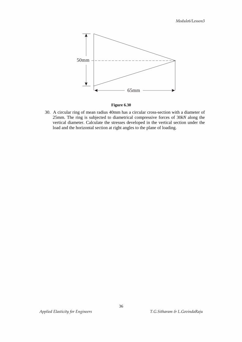
Figure 6.30
30. A circular ring of mean radius 40mm has a circular cross-section with a diameter of 25mm. The ring is subjected to diametrical compressive forces of 30kN along the vertical diameter. Calculate the stresses developed in the vertical section under the load and the horizontal section at right angles to the plane of loading.
65mm
50mm