Lecture 10 Environment mapping, Mirroring€¦ · · 2012-10-30o refractive mapping •Mirroring...
54
Computer Graphics Lecture 10 Environment mapping, Mirroring
Transcript of Lecture 10 Environment mapping, Mirroring€¦ · · 2012-10-30o refractive mapping •Mirroring...
Computer Graphics
Lecture 10 Environment mapping, Mirroring
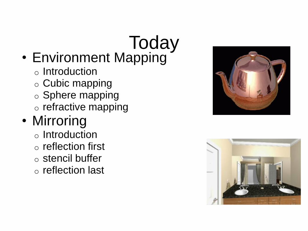
Today • Environment Mapping
o Introduction o Cubic mapping o Sphere mapping o refractive mapping
• Mirroring o Introduction o reflection first o stencil buffer o reflection last

Environment Mapping : Background
• Many objects in the world are glossy or transparent • Glossy objects reflect the external world • The world is refracted through the transparent
objects • Important to make the virtual scene to appear realistic

Example
Terminator II

Environment Mapping: Background (2)
• Precisely simulating such phenomena is computationally costly
• Requires ray tracing, which can be expensive • Tracking the rays and finding out where they collide,
further doing a lighting computation there

Environment Mapping
• Simple yet powerful method to generate reflections • Simulate reflections by using the reflection vector to
index a texture map at "infinity". • Then only need to care the direction of the reflection vector • Also no need to do a lighting computation at the other end
The original environment map was a sphere [by Jim Blinn ’76]

Today • Environment Mapping
o Introduction o Cubic mapping o Sphere mapping o Refractive mapping
• Mirroring o Introduction o reflection first o stencil buffer o reflection last

Cubic Mapping
• The most popular method • The map resides on the
surface of a cube around the object o align the faces of the cube
with the coordinate axes

Procedure
1. During the rasterization, for every pixel, 2. Calculate the reflection vector R using the camera (incident)
vector and the normal vector of the object N 3. Select the face of the environment map and the pixel on the
face according to R 4. Colour the pixel with the colour of the environment map
Look up the environment map just using R Do not take into account the 3D position of the reflection point

Calculating the reflection vector
• Normal vector of the surface : N • Incident Ray : I • Reflection Ray: R • N,I,R all normalized
R = 2 N ( N . I ) - I • The texture coordinate is based
on the reflection vector • Assuming the origin of the
vector is always in the center of the cube environment map

Indexing Cubic Maps • Assume you have R and the
cube’s faces are aligned with the coordinate axes
• How do you decide which face to use?
The reflection vector coordinate with the largest magnitude
R=(0.3, 0.2, 0.8) -> face in +z direction

Indexing Cubic Maps • How do you decide which texture coordinates to use?
o Divide by the coordinate with the largest magnitude o Now ranging [-1,1] o Remapped to a value between 0 and 1.
(0.3,0.2,0.8) --> ((0.3/0.8 +1)*0.5, ((0.2/0.8 +1)*0.5) = (0.6875, 0.625)

Made from the Forum Images
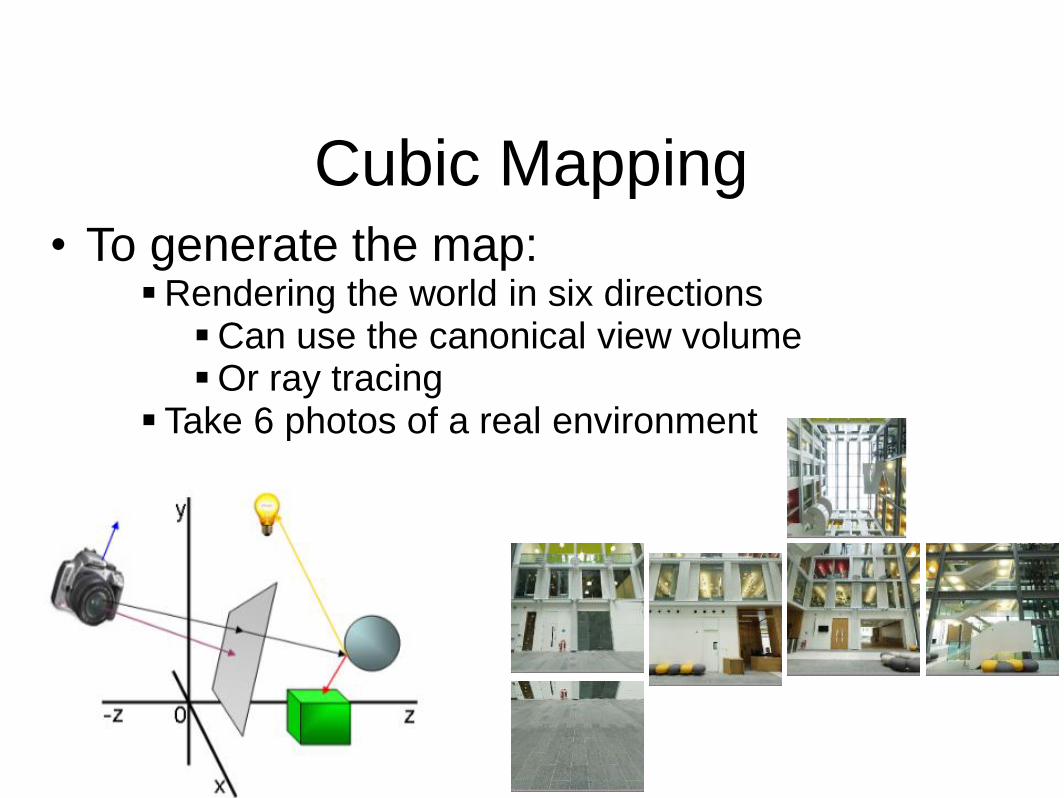
Cubic Mapping • To generate the map:
Rendering the world in six directions Can use the canonical view volume Or ray tracing
Take 6 photos of a real environment

What are the potential problems? How is it different from rendering the scene more accurately? What will we miss by environment mapping?
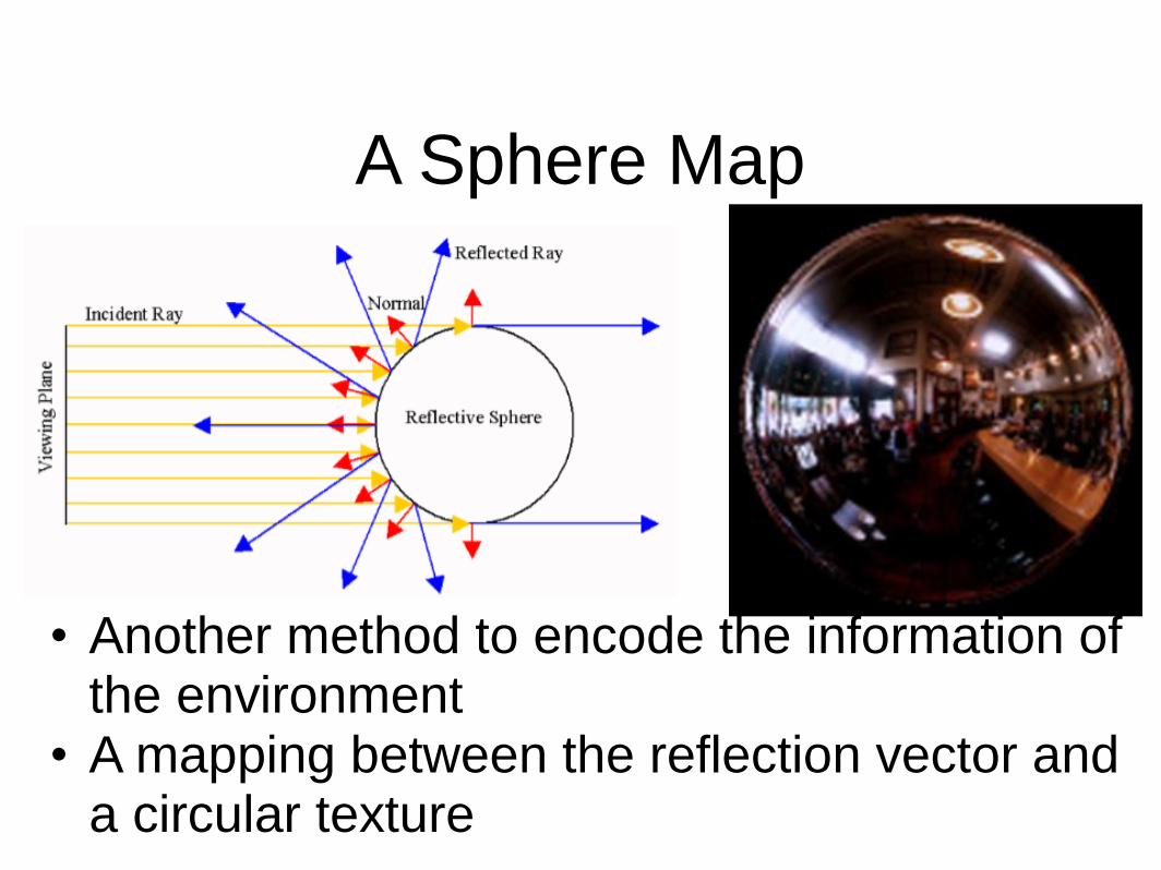
A Sphere Map
• Another method to encode the information of the environment
• A mapping between the reflection vector and a circular texture

A Sphere Map
• The whole environment data is in a single image!
• The resolution near the boundary of the sphere is quite low…

Sphere Map : Procedure
• Compute the reflection vector at the surface of the object
• Find the corresponding texture on the sphere map
• Use the texture to color the surface of the object

Indexing Sphere Maps • Given the reflection vector R (Rx,Ry,Rz)
• (u,v) on the spherical map
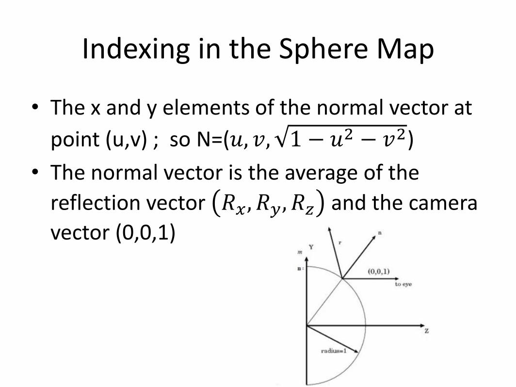
Indexing in the Sphere Map
• The x and y elements of the normal vector at
point (u,v) ; so N=(𝑢, 𝑣, 1 − 𝑢2 − 𝑣2)
• The normal vector is the average of the
reflection vector 𝑅𝑥, 𝑅𝑦, 𝑅𝑧 and the camera
vector (0,0,1)

Indexing in the Sphere Map
• N= (𝑅𝑥
2𝑚,
𝑅𝑦
2𝑚,
𝑅𝑧
2𝑚+
1
2)
Where
• Therefore, given the reflection vector, the index in the sphere map can be computed by
• (u,v) = ( )
• Assuming the center is (1/2,1/2)

Generating a Sphere Map o For synthetic scenes, you can use ray tracing o Mapping a cubic environment map onto a sphere o Take a photograph of a shiny sphere

Issues with Sphere Mapping • Cannot change the viewpoint • Requires recomputing the sphere map
• Highly non-uniform sampling • Highly non-linear mapping • Linear interpolation of texture coordinates picks up the
wrong texture pixels • Do per-pixel sampling or use high resolution polygons
Correct Linear

How can you make the right image from the left image?
Where does middle point on the right image corresponds to? by Mark VandeWettering

Cons and Pros
• How do you compare cube mapping and sphere
mapping? o Advantages of cube mapping? o Problem of sphere mapping?

Refractive Environment Mapping
• When simulating effects mapping the refracted environment onto translucent materials such as ice or glass, we must use Refractive Environment Mapping

Snell’s Law
• When light passes through a boundary between two materials (air and water, for example), the light’s direction changes.

Snell’s Law
• Light travels at different speed in different media

Snell’s Law
• i: incident vector • t: refraction vector 𝒕 = 𝑟𝒊 + 𝑤 − 𝑘 𝒏 where
𝑟 =𝑛1
𝑛2
𝑤 = − 𝒊 ∙ 𝒏 𝑟
𝑘 = 1 + (𝑤 − 𝑟)(𝑤 + 𝑟)

Refractive Environment Mapping
• Use the refraction vector after the first hit as the index to the environment map – Costly to compute the second refraction vector
• Better use cubic mapping - Why?

Summary
• Environment mapping is a quick way to simulate the effect of reflecting the world at the surface of a glossy object
• Practical approaches are the cubic mapping and the sphere mapping
• Can also be applied for simulating refraction

Today • Environment Mapping
o Introduction o Cubic mapping o Sphere mapping o refractive mapping
• Mirroring o Introduction o reflection first o stencil buffer o reflection last

Mirroring (Flat Mirrors) : Background
• Basic idea: Drawing a scene with mirrors
• Mirrors reflect the world • A scene with a mirror can be drawn
by rendering the world twice • original scene, and • reflected scene
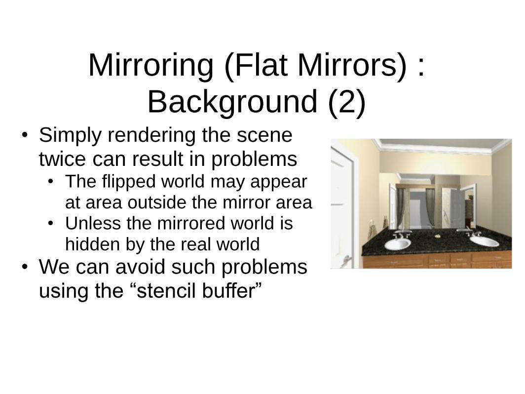
Mirroring (Flat Mirrors) : Background (2)
• Simply rendering the scene twice can result in problems • The flipped world may appear
at area outside the mirror area • Unless the mirrored world is
hidden by the real world
• We can avoid such problems using the “stencil buffer”

Reflecting Objects • If the mirror is on a plane
that passes through the origin, and
• is aligned with a coordinate axis, then just negate appropriate coordinate
• For example, if a reflection plane has a normal n=(0,0,1) and passes the origin, the reflected vertices can be obtained by scaling matrix S(1,1,-1)
Mirror Wall

Reflecting Objects (2) • What if the mirror is not
on a plane that passes the origin?
• How do we compute the mirrored world?
• First, we need to compute the location of objects relative to the mirror
Mirror Wall Mirror
p
n
O

Recap:
M

Reflecting Objects (3) • To know the positions of
objects with respect to the mirror coordinate,
• we multiply a transformation matrix from the mirror to the world coordinate to their positions in the world coordinate
Mirror Mirror
n
𝑥′ = 𝑅 𝑛 −1𝑇 −𝑝 𝑥
O
p x’’
x
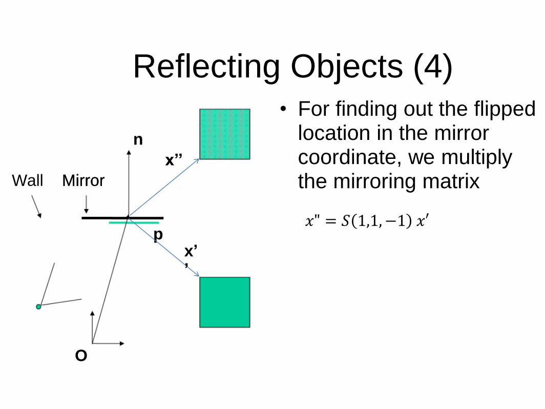
Reflecting Objects (4) • For finding out the flipped
location in the mirror coordinate, we multiply the mirroring matrix
Mirror Wall Mirror
p
n
𝑥" = 𝑆 1,1, −1 𝑥′
O
x’’
x’’

Reflecting Objects (5) • Now we want to know
where the flipped points are with respect to the world origin
• We can multiply the transformation matrix to move from the origin to the mirror to x’’ to know where it is with respect to O
Mirror Wall Mirror
p
n
𝑥′′′ = 𝑇 𝑝 𝑅(𝑛) 𝑥′′ O
x’’’
x’’

Reflecting Objects (6) • Altogether,
Mirror Wall Mirror
p
n
𝑥′′′ = 𝑇 𝑝 𝑅(𝑛) 𝑥′′
O
x’’’
x’’ 𝑥" = 𝑆 1,1, −1 𝑥′
𝑥′ = 𝑅 𝑛 −1𝑇 −𝑝 𝑥
𝑥′′′ = 𝑇 𝑝 𝑅 𝑛 𝑆 1,1, −1 𝑅 𝑛 −1𝑇 −𝑝 𝑥
𝑀𝑚𝑖𝑟𝑟𝑟𝑜𝑟 = 𝑇 𝑝 𝑅 𝑛 𝑆 1,1, −1 𝑅 𝑛 −1𝑇 −𝑝

Drawing the original and mirrored world Two different orders in doing it: 1. Draw the mirrored world first, then the real world • Only using the depth (Z) buffer • Does not work in some cases
2. Draw the real-world first, and then the mirrored world • Requires using a stencil buffer

Rendering Reflected First
(Using the depth buffer(Z-buffer)) • First pass: Render the reflected scene
without mirror, depth test on
• Second pass: o Disable the color buffer, and render the
mirror polygon (to not draw over the reflected scene)
o Now the depth buffer of the mirror region is set to the mirror’s surface
• Third Pass: o Enable the color buffer again o Render the original scene, without the
mirror o Depth buffer stops from writing over
things in mirror

Reflection Example
The color buffer after the final pass

Avoid drawing the reflected world appearing in the real world
• Specify a user-defined clipping plane
– Every thing in front of the clipping plane will not be displayed
– Set it at the plane where the mirror is set
Mirror Mirror
n
User defined clipping plane

Reflected Scene First (issues)
• Objects behind the mirror cause problems: o The reflected area outside the
mirror region is just overwritten by the objects in the front
o unless there is a wall, they will remain visible
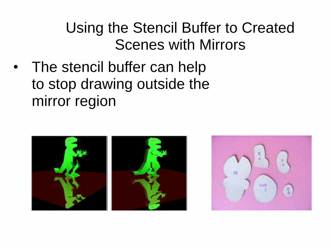
Using the Stencil Buffer to Created Scenes with Mirrors
• The stencil buffer can help to stop drawing outside the mirror region

Stencil Buffer
• The stencil buffer acts like a paint stencil
• It lets some fragments through but not others
• You specify two things: o The test that controls which
fragments get through o The operations to perform on
the buffer when the test passes or fails

Stencil Tests • You give an operation, a
reference value, and a mask
• Operations: o Always let the fragment
through o Never let the fragment
through o Logical operations between
the reference value and the value in the buffer: <, <=, =, !=, >, >=

Stencil Operations • Specify three different operations
o If the stencil test fails o If the stencil passes but the depth test fails o If the stencil passes and the depth test passes
• Operations are: o Keep the current stencil value o Zero the stencil o Replace the stencil with the reference value o Increment the stencil o Decrement the stencil o Invert the stencil (bitwise)

mirror
Reflection Example
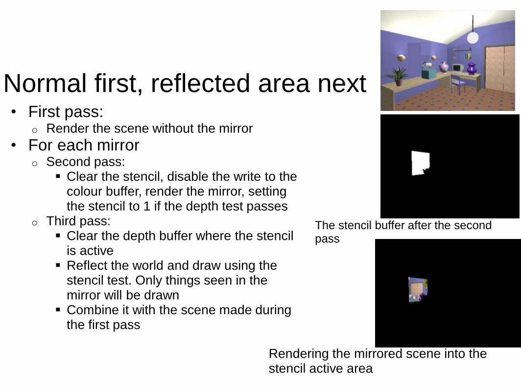
Normal first, reflected area next • First pass:
o Render the scene without the mirror
• For each mirror o Second pass:
Clear the stencil, disable the write to the colour buffer, render the mirror, setting the stencil to 1 if the depth test passes
o Third pass: Clear the depth buffer where the stencil
is active Reflect the world and draw using the
stencil test. Only things seen in the mirror will be drawn
Combine it with the scene made during the first pass
The stencil buffer after the second pass
Rendering the mirrored scene into the stencil active area

Multiple mirrors
• Can manage multiple mirrors o Render normal view, then do other
passes for each mirror
• A recursive formulation exists for mirrors that see other mirrors o After rendering the reflected area
inside the mirror surface, render the mirrors inside the mirror surface, and so on

Readings
• Foley 16.5-6 • Real-time Rendering 2, Chapter 5.7, 6.10
Reference http://brainwagon.org/2002/12/05/fun-with-environment-maps/