Lecture 1: basics Oscilloscope & SPICE Basics. Lecture outline Course Goals/Outline The Oscilloscope...
24
lecture 1: basics Oscilloscope & SPICE Basics
-
Upload
suzan-sparks -
Category
Documents
-
view
225 -
download
0
Transcript of Lecture 1: basics Oscilloscope & SPICE Basics. Lecture outline Course Goals/Outline The Oscilloscope...

lecture 1:basics
Oscilloscope & SPICE Basics
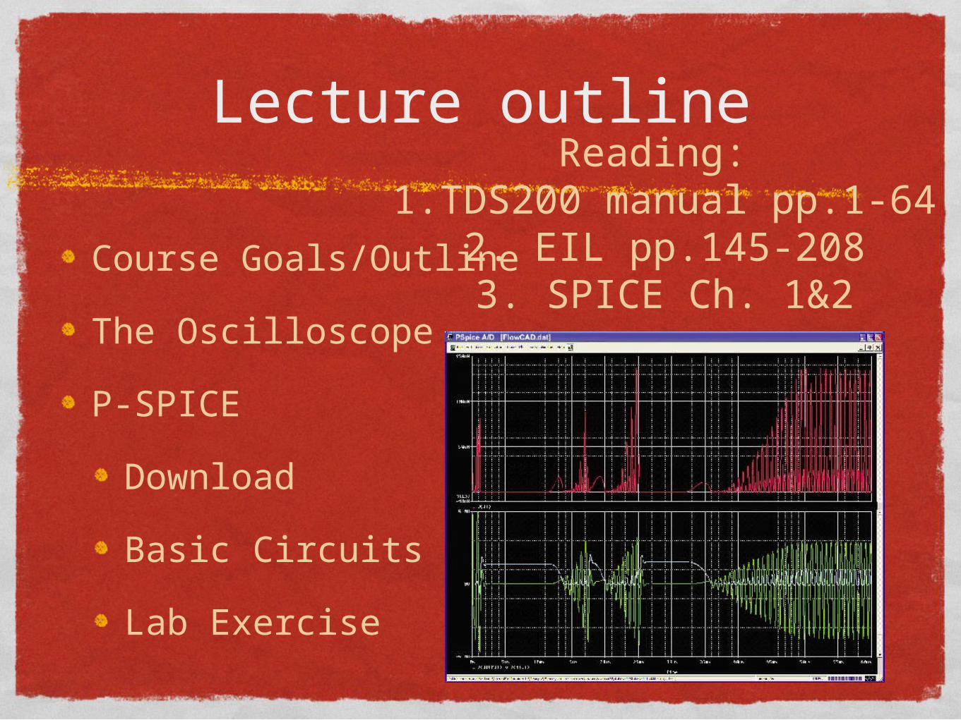
Lecture outline
Course Goals/Outline
The Oscilloscope
P-SPICE
Download
Basic Circuits
Lab Exercise
Reading: 1.TDS200 manual pp.1-64
2. EIL pp.145-2083. SPICE Ch. 1&2
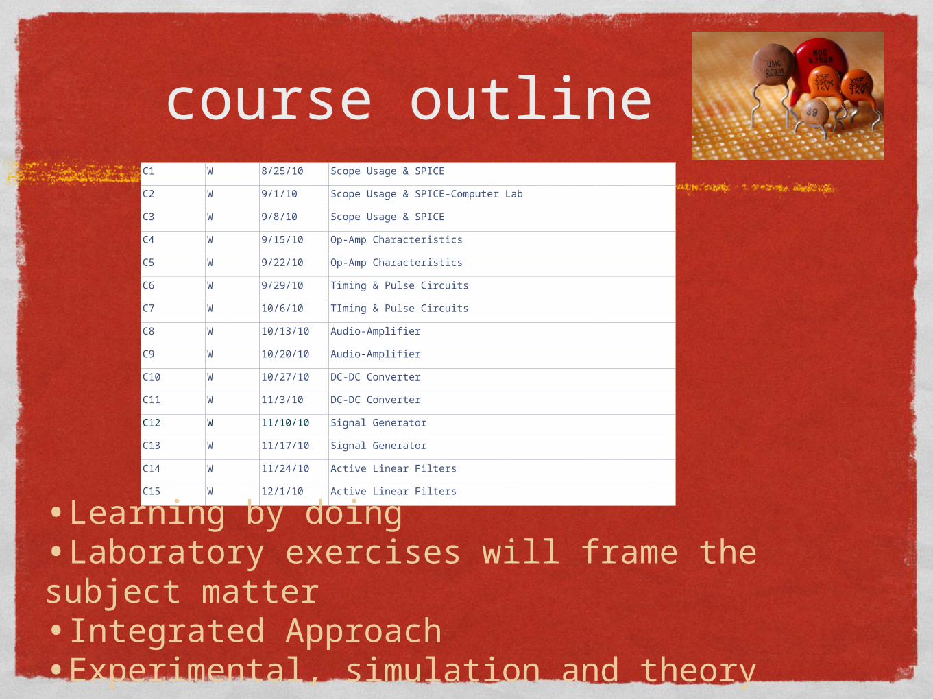
course outlineC1 W 8/25/10 Scope Usage & SPICE
C2 W 9/1/10 Scope Usage & SPICE-Computer Lab
C3 W 9/8/10 Scope Usage & SPICE
C4 W 9/15/10 Op-Amp Characteristics
C5 W 9/22/10 Op-Amp Characteristics
C6 W 9/29/10 Timing & Pulse Circuits
C7 W 10/6/10 TIming & Pulse Circuits
C8 W 10/13/10 Audio-Amplifier
C9 W 10/20/10 Audio-Amplifier
C10 W 10/27/10 DC-DC Converter
C11 W 11/3/10 DC-DC Converter
C12 W 11/10/10 Signal Generator
C13 W 11/17/10 Signal Generator
C14 W 11/24/10 Active Linear Filters
C15 W 12/1/10 Active Linear Filters
•Learning by doing•Laboratory exercises will frame the subject matter•Integrated Approach•Experimental, simulation and theory

gradingLab Demonstrations -30%
Prelab & Demo
Lab Reports & Lab Notebook -30%
Notebook is like 1 report
Exams-30%
In-class or take home
In-class quizzes-10%
Surprise quizzes
Recitation attendance is mandatory
Grade penalty in syllabus
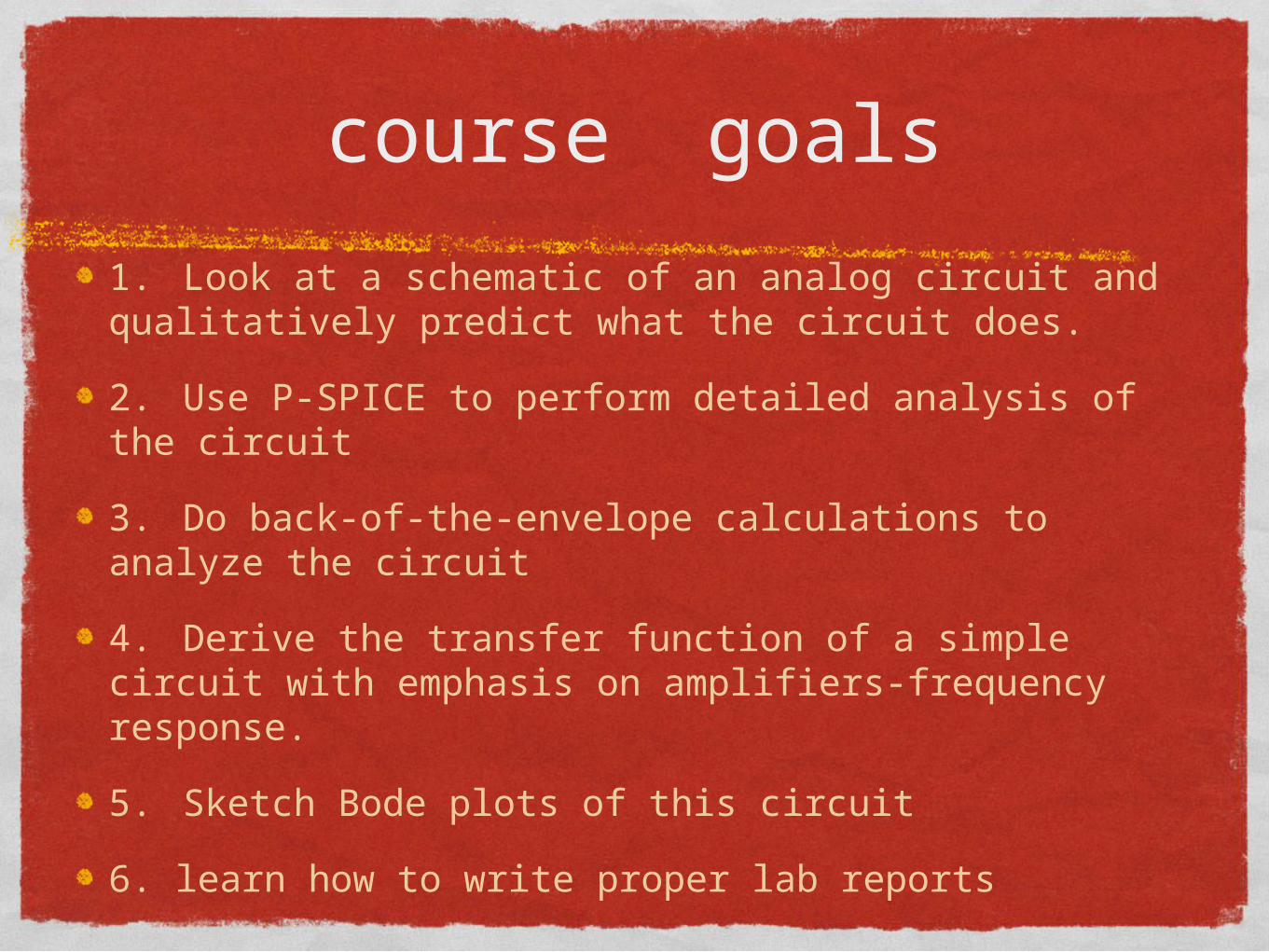
course goals
1. Look at a schematic of an analog circuit and qualitatively predict what the circuit does.
2. Use P-SPICE to perform detailed analysis of the circuit
3. Do back-of-the-envelope calculations to analyze the circuit
4. Derive the transfer function of a simple circuit with emphasis on amplifiers-frequency response.
5. Sketch Bode plots of this circuit
6. learn how to write proper lab reports

Lab reports
Introduction
Theory
Experimental
Results / Discussion
Conclusions
References

Introduction
The introduction is exactly what it says. It is a paragraph or series of paragraphs that introduce the reader to the subject
The introduction presents basic background material, the history of the problem, or introduces most of the major references
Provide a schematic as well
Use formal language. A conversational style is NOT acceptable (see example of tech memo)

Theory (or background)
Explains the theory behind the work and is the proper place for the mathematics
Contains the general equations that describe the system under study

experimentalExplanations for the apparatus, instruments, calibrations, etc.
Expected error and repeatability can be introduced
Describe what you did in the simplest way possible
Diagrams are always helpful

Results/discussion
All results of the lab activity are reported here
This includes simulation and experimental results
Appropriate tabular and graphical form should be used
All x-axis and y-axis scales should be clearly indicated (e.g., current probe measurements y-axis scale) along with UNITS!!!
It is encouraged that you mark the scope captures with a pen showing relevant features or noting numerical values of significance. It is understood that for a formal report you would use some kind of CAD program to mark the figures
results/discussion
All results should be discussed and compared with theoretical predictions and simulation results
Discrepancies should be noted and an attempt to explain them should be made
Are these the results you expect? Why?
Do you notice discrepancies? What is causing these?

conclusion
The conclusions should be a specific and factual summary of the report
The conclusions should tie-up loose ends from the previous portions of the report such as speculation and questions, and analysis of the error.

rubric for lab report

rubric for lab report

the oscilloscope
Oscilloscope displays voltages visually
Coupling-AC, DC and GND
Triggering-tells scope when to start displaying
Analysis & Measurement utilities
In the old days was all-analog
Nowadays digital

analog o-scope
Like a TV in many ways.

subsystems
Display-analog or digital, LCD, CRT etc.
Time-base, x-axis control-Trigger-int. or ext.
Signal, Y-axis control-input, coupling
Power supplies-fuses etc.
Probes 1x, 10x etc. attenuation amount
Calibration circuits -compensate input R, C
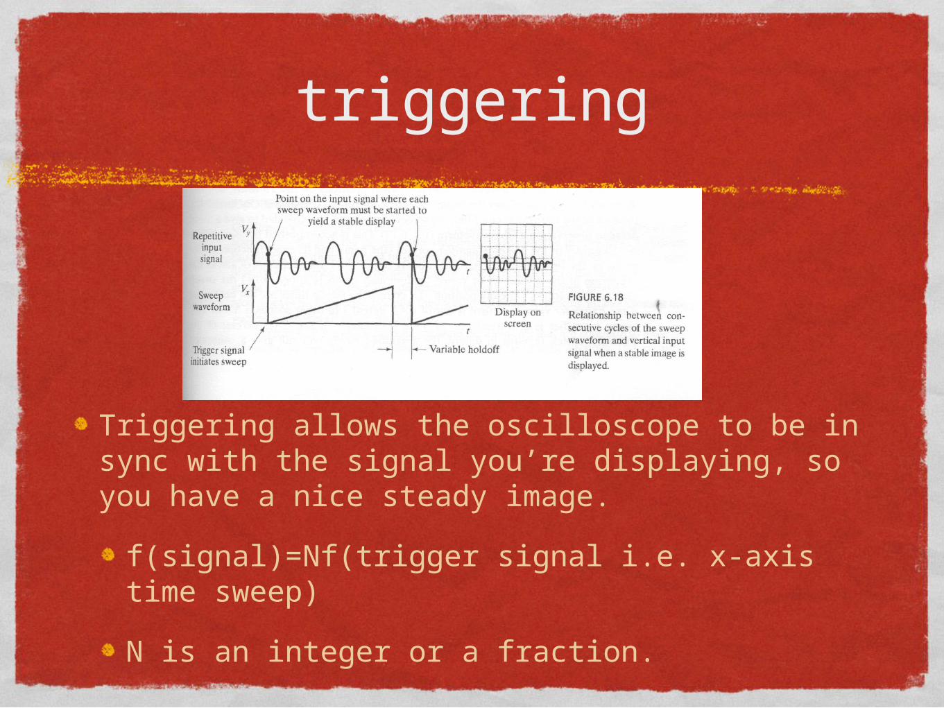
triggering
Triggering allows the oscilloscope to be in sync with the signal you’re displaying, so you have a nice steady image.
f(signal)=Nf(trigger signal i.e. x-axis time sweep)
N is an integer or a fraction.

Sampling
Digital o-scopes are not continuous
Each screen has a fixed # of samples
How many for TDS200?
Smapling rate changes with time base
If sampling is too little, aliasing can occur
Like wheel turning backward in car commercials
What determines minimum required sampling?

triggeringCan be made to be one-shot to capture single events.
How can you do this?
This will be the exercise for the first lab
capture a manual switch event.

ORCAD P-spiceSPICE is a circuit simulation program-industry standard
You create a circuit
different circuit editors
Then you simulate it!
Gives you currents, voltages, transients etc.
Download student version on your own computerhttp://www.electronics-lab.com/downloads/
schematic/013/

P-SPICE TIPS
Need a ground!
ONLY use the “0” source in power sources
Make sure you add the required libraries
There are 3 ways to simulate
Text editor
ORCAD Capture
ORCAD Schematic

p-spice Resources
http://www.uta.edu/ee/hw/pspice/
http://www.youtube.com/watch?v=dZUPBLNuaHk
This is for Capture
The download page also has many resources
I will post a SPICE reference also.

work through prelabSwitch debouncer