
Lecture 03: Stress - Worcester Polytechnic...
28
Mechanical Engineering Department WORCESTER POLYTECHNIC INSTITUTE MECHANICAL ENGINEERING DEPARTMENT STRESS ANALYSIS ES-2502, C’2012 Lecture 03: Stress 17 January 2012
Transcript of Lecture 03: Stress - Worcester Polytechnic...

Mechanical Engineering Department
WORCESTER POLYTECHNIC INSTITUTE MECHANICAL ENGINEERING DEPARTMENT
STRESS ANALYSIS ES-2502, C’2012
Lecture 03: Stress
17 January 2012

Mechanical Engineering Department
Instructor: Cosme Furlong HL-151
(508) 831-5126 [email protected]
http://www.wpi.edu/~cfurlong/es2502.html
General information
Teaching Assistants: Morteza Khaleghi HL-150
(508) 831-5125 [email protected]
Tatiana Popova

Mechanical Engineering Department
Actual mechanism
Schematic representation:
Free-body diagram:
Operator applies 20-lb to pedal
stretching spring by 1.5 in.
Free-body diagrams

Mechanical Engineering Department
Overall FBD
Number of unknowns ?
Equilib. Equations ?
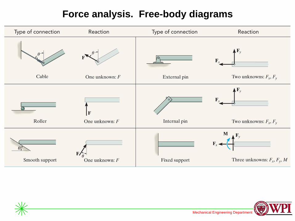
Force analysis. Free-body diagrams
Is this a statically
indetermined case ?
Mechanical Engineering Department
Force analysis. Free-body diagrams

Mechanical Engineering Department
3D
2D
Individual FBD’s
Overall FBD
Number of unknowns ?
Equilib. Equations ?
Force analysis. Free-body diagrams
Mechanical Engineering Department
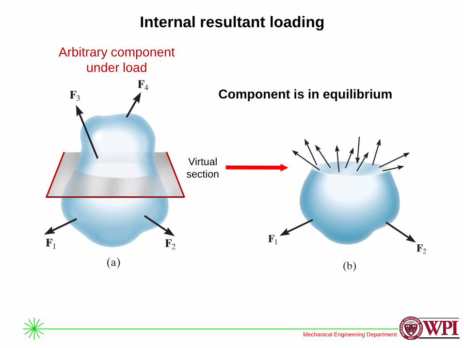
Internal resultant loading
Arbitrary component
under load
Component is in equilibrium
Virtual
section
Mechanical Engineering Department
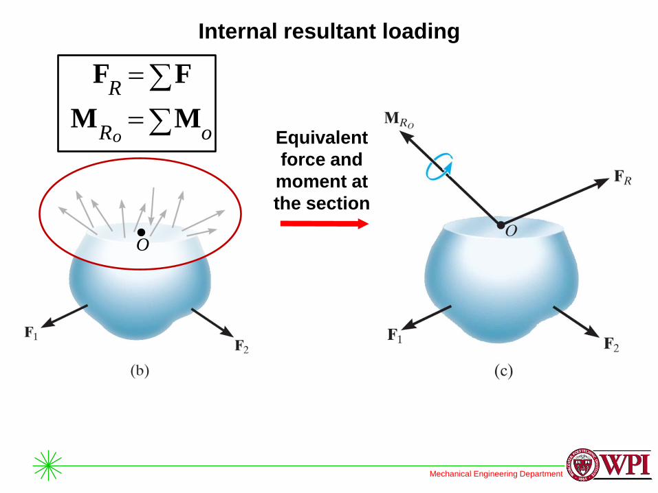
Internal resultant loading
Equivalent
force and
moment at
the section
FFR
oRoMM
O
Mechanical Engineering Department
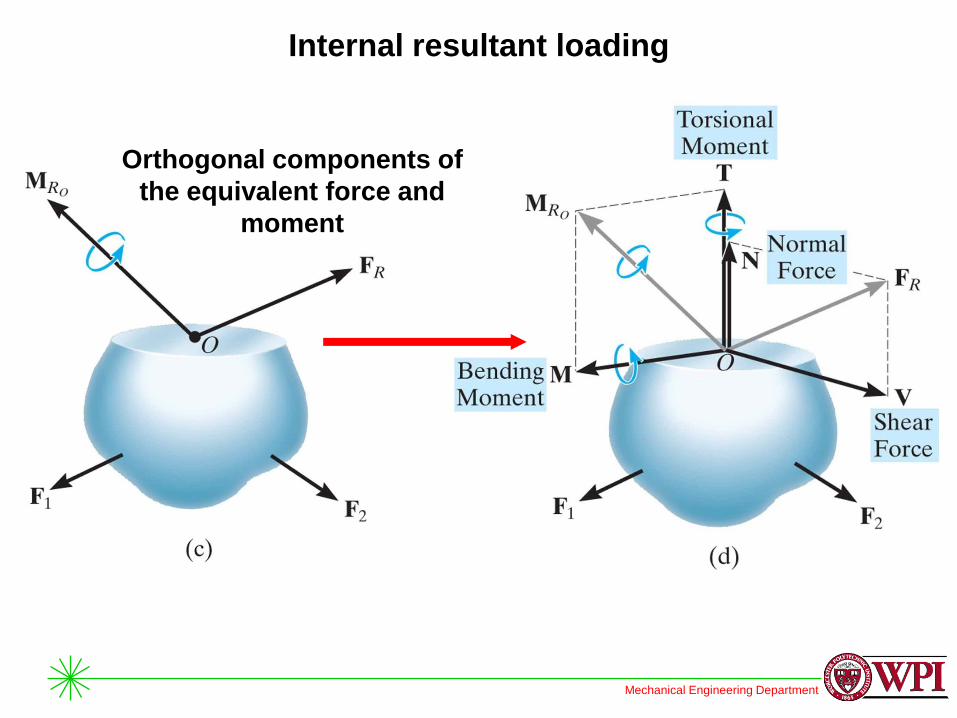
Internal resultant loading
Orthogonal components of
the equivalent force and
moment

Mechanical Engineering Department
Internal resultant loading
Component is in equilibrium
Equivalent forces and
moments at the section
Mechanical Engineering Department
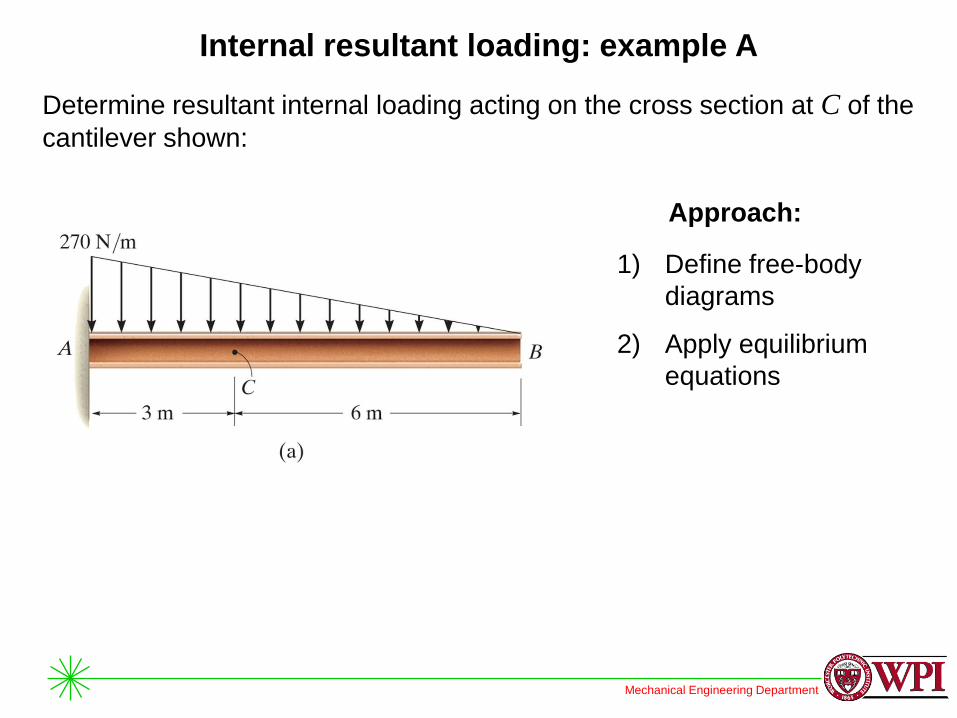
Internal resultant loading: example A
Determine resultant internal loading acting on the cross section at C of the
cantilever shown:
Approach:
1) Define free-body
diagrams
2) Apply equilibrium
equations

Mechanical Engineering Department
Internal resultant loading: example A
Section to the
right of C
Section to the
left of C Use either section
to determine
internal loadings
Free-body
diagrams
(FBDs):

Mechanical Engineering Department
Internal resultant loading: example B
Determine resultant internal loading acting on the cross section at C of the
machine shaft shown. Shaft is supported by bearings at A and B, which
only exert radial forces on the shaft
Approach:
1) Define free-body
diagrams
2) Apply equilibrium
equations: reactions
at bearings
3) Apply equilibrium
equations: internal
loading

Mechanical Engineering Department
Internal resultant loading: example B
Overall free-body diagram
(FBD)
FBD is in2D, why?
C
x
y

Mechanical Engineering Department
Internal resultant loading: example B
Select and define free-body diagram of
section (FBD)
C
x
y
Compute internal loading

Mechanical Engineering Department
Internal resultant loading: example C
Determine the resultant internal torque acting on the cross sections
through points C and D. Supports A and B allow free turning of the shaft
Approach:
1) Define free-body
diagram
2) Apply equilibrium
equations

Mechanical Engineering Department
Internal resultant loading: example D
The force F= 80 lbf acts on the gear tooth. Determine the resultant internal
loadings on the root of the tooth, i.e., at the centroid point A of section a-a
Approach:
1) Define free-body
diagram
2) Apply equilibrium
equations

Mechanical Engineering Department
Stress. Definition: intensity of internal force: acting on a
specific plane passing through a point
Equivalent
force and
moment at
the section
FFR
oRoMM
O

Mechanical Engineering Department
Stress. Definition: intensity of internal force: acting on a
specific plane passing through a point
Finite force F acting on
a finite area A
Definition
Normal stress:
A
Fz
Az
0lim

Mechanical Engineering Department
Stress. Definition: intensity of internal force: acting on a
specific plane passing through a point
Finite force F acting
on a finite area A Definitions
Shear stresses:
A
Fx
Azx
0lim
A
Fy
Azy
0lim
A

Mechanical Engineering Department
Stress. Definition: intensity of internal force: acting on a
specific plane passing through a point
Finite force F acting on
a finite area A
Normal and shear
stresses on plane x

Mechanical Engineering Department
General state of stresses
Further sectioning leads
to a “stress cube”
State of stresses of
a finite size cube

Mechanical Engineering Department
Average normal stress in an axially loaded bar
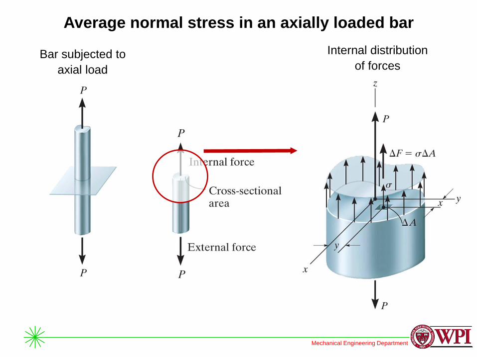
Mechanical Engineering Department
Average normal stress in an axially loaded bar
Bar subjected to
axial load
Internal distribution
of forces

Mechanical Engineering Department
Average normal stress in an axially loaded bar
Internal distribution
of forces zRz FF
A
dAdF
AP
Average normal stress:
A
P

Mechanical Engineering Department
Average normal stress in an axially loaded bar
Tensile average
normal stress
Compressive
average normal
stress
Mechanical Engineering Department
Reading assignment
• Chapter 1 of textbook
• Review notes and text: ES2001, ES2501

Mechanical Engineering Department
Homework assignment
• As indicated on webpage of our course


