Learning Grasping Points with Shape Context
36
Learning Grasping Points with Shape Context Jeannette Bohg, Danica Kragic Computer Vision and Active Perception Lab Centre for Autonomous Systems School of Computer Science and Communication Royal Institute of Technology, 10044 Stockholm, Sweden {bohg, danik}@csc.kth.se Abstract This paper presents work on vision based robotic grasping. The proposed method adopts a learning framework where prototypical grasping points are learnt from several examples and then used on novel objects. For representa- tion purposes, we apply the concept of shape context and for learning we use a supervised learning approach in which the classifier is trained with labelled synthetic images. We evaluate and compare the performance of linear and non- linear classifiers. Our results show that a combination of a descriptor based on shape context with a non-linear classification algorithm leads to a stable detection of grasping points for a variety of objects. Key words: Grasping, Shape Context, Affordances, SVM 1. Introduction Robotic grasping of unknown objects remains an open problem in the robotic community. Although humans master this skill easily, no suitable representa- tions of the whole process have yet been proposed in the neuroscientific lit- erature, making it difficult to develop robotic systems that can mimic human grasping behaviour. However, there is some valuable insight. Goodale [1] pro- poses that the human visual system is characterised by a division into the dorsal and ventral pathways. While the dorsal stream is mainly responsible for the spatial vision targeted towards extracting action relevant visual features, the ventral stream is engaged in the task of object identification. This dissociation also suggests two different grasp choice mechanisms dependent on whether a known or unknown object is to be manipulated. Support for this can be found in behavioural studies by Borghi [2], Creem and Proffitt [3]. The authors claim that in the case of novel objects, our actions are purely guided by affordances as introduced by Gibson [4]. In the case of known objects, semantic information (e.g., through grasp experience) is needed to grasp them appropriately accord- ing to their function. However as argued in [1, 5, 6] this division of labour is not absolute. In case of objects that are similar to previously encountered ones, Preprint submitted to Robotics and Autonomous Systems November 2, 2009
Transcript of Learning Grasping Points with Shape Context
Learning Grasping Points with Shape Context
Jeannette Bohg, Danica Kragic
Computer Vision and Active Perception Lab
Centre for Autonomous Systems
School of Computer Science and Communication
Royal Institute of Technology, 10044 Stockholm, Sweden
{bohg, danik}@csc.kth.se
Abstract
This paper presents work on vision based robotic grasping. The proposedmethod adopts a learning framework where prototypical grasping points arelearnt from several examples and then used on novel objects. For representa-tion purposes, we apply the concept of shape context and for learning we usea supervised learning approach in which the classifier is trained with labelledsynthetic images. We evaluate and compare the performance of linear and non-linear classifiers. Our results show that a combination of a descriptor basedon shape context with a non-linear classification algorithm leads to a stabledetection of grasping points for a variety of objects.
Key words: Grasping, Shape Context, Affordances, SVM
1. Introduction
Robotic grasping of unknown objects remains an open problem in the roboticcommunity. Although humans master this skill easily, no suitable representa-tions of the whole process have yet been proposed in the neuroscientific lit-erature, making it difficult to develop robotic systems that can mimic humangrasping behaviour. However, there is some valuable insight. Goodale [1] pro-poses that the human visual system is characterised by a division into the dorsaland ventral pathways. While the dorsal stream is mainly responsible for thespatial vision targeted towards extracting action relevant visual features, theventral stream is engaged in the task of object identification. This dissociationalso suggests two different grasp choice mechanisms dependent on whether aknown or unknown object is to be manipulated. Support for this can be foundin behavioural studies by Borghi [2], Creem and Proffitt [3]. The authors claimthat in the case of novel objects, our actions are purely guided by affordances asintroduced by Gibson [4]. In the case of known objects, semantic information(e.g., through grasp experience) is needed to grasp them appropriately accord-ing to their function. However as argued in [1, 5, 6] this division of labour isnot absolute. In case of objects that are similar to previously encountered ones,
Preprint submitted to Robotics and Autonomous Systems November 2, 2009

the ventral system helps the dorsal stream in the action selection process byproviding information about prehensile parts along with their afforded actions.
In this paper, we review different approaches towards solving the objectgrasping problem in the robotic community and propose a vision based systemthat models several important steps in object grasping. We start by proposingthree ways for approaching the problem, namely grasping of:
• Known Objects: These approaches consider grasping of a priori knownobjects. The goal is then to estimate object’s pose and retrieve a suitablegrasp, e.g., from an experience database, [7, 8, 9].
• Unknown Objects : Approaches that fall into this category commonly rep-resent the shape of an unknown object and apply rules or heuristics toreduce the number of potential grasps [10, 11, 12, 13, 14].
• Familiar Objects: These approaches try reusing preexisting grasp experi-ence from similar objects. Objects can be familiar in different ways, e.g,in terms of shape, colour or texture. A common assumption is that newobjects similar to the old ones can be grasped in a similar way [15, 16, 17].
A general observation considering the related work is that there is a trade-offbetween the quality of an inferred grasp and the applicability of the method ina real world scenario. The more precise, accurate and detailed an object model,the more suitable it is for doing grasp planning. Then criteria such as, e.g.,form or force closure can be taken into account to plan a stable grasp. However,when facing noise and outliers common in real world data, more assumptionsregarding object geometry or generated grasps have to be introduced. Figure 1outlines a rough taxonomy for the related work with respect to object repre-sentation on which we will elaborate in Section 2. Systems that either relyexclusively on 2D or on 3D data have some disadvantages in terms of intro-duced assumptions or strong dependency on the quality of the sensor data. Wedevelop a representation that integrates data from both modalities as a way toovercome these issues.
The representation has to be rich enough to allow for the inference of themost important grasp parameters. In our case that is
• the grasping point on the object with which the tool centre point (TCP)should be aligned 1,
• the approach vector [7] which describes the 3D angle that the robot handapproaches the grasping point with and
• the wrist orientation of the robotic hand.
In our approach, a grasping point is detected based on the global shape ofan object in a single image. Research in the area of neuropsychology empha-sises the influence of global shape when humans choose a grasp [18, 19, 20].
1In this paper the TCP is at the centre of palm of the robotic gripper.
2

Object
2D Representation
Integrated
3D Representation
Grasp Configuration
(1)
(2)
(3)
Figure 1: Grasp inference systems with respect to employed representation. (1) Approachesthat use 3D data for representing the object are usually strongly dependent on good qualityof the sensory data. See Section 2.2 and 2.3.1.(2) Approaches that use 2D information onlyfor inferring a grasp usually have to make strong assumptions about applicable actions or the3D shape of the object. See Section 2.3.2. (3) Systems that integrate 2D and 3D data areable to remove some assumptions made when using 2D only and are less dependent on thequality of the 3D data.
Matching between stereo views is then used to infer the approach vector andwrist orientation for the robot hand. We further demonstrate how a supervisedlearning methodology can be used for grasping of familiar objects.
The contributions of our approach are:i) We apply the concept of shape context [21] to the task of robotic graspingwhich to the best of our knowledge has not yet been applied for that purpose.The approach is different from the one taken in [15, 17] where only local ap-pearance is used instead of global shape.ii) We infer grasp configurations for arbitrarily shaped objects from a stereoimage pair. These are the main difference to the work presented in [16, 22]where either only planar objects are considered or three views from an objecthave to be obtained by moving the camera.iii) We analyse how stable our algorithm is in realistic scenarios including back-ground clutter without trained scenario examples as in [15].iv) We apply a supervised learning algorithm trained using synthetic labelledimages from the database provided by [15]. We compare the classification per-formance when using a linear classifier (logistic regression) and a non-linearclassifier (Support Vector Machines (SVMs)).
The remainder of this paper is organised as follows: In the next section, wepresent related work. In Section 3, the method of applying shape context tograsping is introduced. We also describe and comment on the database thatwe used for training and give some background knowledge on the two differentclassification methods. The section concludes with a presentation on how awhole grasp configuration can be derived. In Section 4 we evaluate our methodboth on simulated and real data. The last section concludes the paper and givesan outlook on future work.
3

2. Related Work
There is a significant body of work dealing with grasp selection. We use thedivision proposed in the previous section to review the related work.
2.1. Grasping Known Objects
The main problem in the area of grasp planning is the huge search spacefrom which a good grasp has to be retrieved. Its size is due to the large numberof hand configurations that can be applied to a given object. In the theoryof contact-level grasping [23, 24] a good grasp is defined from the perspectiveof forces, friction and wrenches. Based on this different criteria are defined torate grasp configurations, e.g., force closure, dexterity, equilibrium, stability anddynamic behaviour.
Several approaches in the area of grasp planning exists that apply these cri-teria to find a good grasp for an object with a given 3D model. Some of themapproximate the object’s shape with a number of primitives such as spheres,cones, cylinders and boxes [25] or superquadrics (SQ) [26]. These shape prim-itives are then used to limit the number of candidate grasps and thus prunethe search tree for finding the most stable grasp. Ciorcarlie et al. [27] exploitedresults from neuroscience that showed that human hand control takes place ina much lower dimension than the actual number of its degrees of freedom. Thisfinding was applied to directly reduce the configuration space of a robotic handto find pre-grasp postures. From these so called eigengrasps the system searchesfor stable grasps. Borst et al. [28] reduce the number of candidate grasps by ran-domly generating a number of them dependent on the object surface and filterthem with a simple heuristic. The authors show that this approach works wellif the goal is not to find an optimal grasp but instead a fairly good grasp thatworks well for “ everyday tasks”. Quite a different approach is taken by Li andPollard [29]. Although, the method is independent of the ideas of contact-levelgrasping it still relies on the availability of a 3D object model. The authors treatthe problem of finding a suitable grasp as a shape matching problem betweenthe hand and the object. The approach starts off with a database of humangrasp examples. From this database a suitable grasp is retrieved when queriedwith a new object. Shape features of this object are matched against the shapeof the inside of the available hand postures.
All these approaches are developed and evaluated in simulation. How-ever, Ekvall and Kragic [7] and Morales et al. [8] combine real and simulateddata for the purpose of grasping known objects, i.e. their 3D model is available.In a monocular image a known object is recognised and its pose within the sceneis estimated. Given that information, an appropriate grasp configuration can beselected from a grasp experience database. This database was acquired offlinethrough simulations of grasps on 3D models of a set of these known objects.While Ekvall and Kragic [7] still apply the selected grasp in simulation, Moraleset al. [8] ported this approach to the robotic platform described in Asfour et al.[30]. Glover et al. [9] consider known deformable objects. For representingthem probabilistic models of their 2D shape are learnt. The objects can then be
4

detected in monocular images of cluttered scenes even when they are partiallyoccluded. The visible object parts serve as a basis for planning a stable graspunder consideration of the global object shape. However, all these approachesare dependent on an a priori known dense or detailed object model either in 2Dor in 3D.
2.2. Grasping Unknown Objects
If the goal is to grasp an unknown object these approaches are not applicablesince in practise it is very difficult to infer its geometry fully and accuratelyfrom measurements taken from sensor devices such as cameras and laser rangefinders. There are various ways to deal with this sparse, incomplete and noisydata. Hubner and Kragic [10], Dunes et al. [11] for example approximate anobject with shape primitives that provide cues for potential grasps. Hubnerand Kragic [10] decompose a point cloud derived from a stereo camera into aconstellation of boxes. The simple geometry of a box reduces the number ofpotential grasps significantly. Dunes et al. [11] approximate the rough objectshape with a quadric whose minor axis is used to infer the wrist orientation, theobject centroid serves as the approach target and the rough object size helpsto determine the hand pre-shape. The quadric is estimated from multi-viewmeasurements of the rough object shape in monocular images. Opposed to theabove mentioned techniques Bone et al. [14] made no prior assumption aboutthe rough shape of the object. They applied shape carving for the purposeof grasping with a parallel-jaw gripper. After obtaining a model of the object,they search for a pair of reasonably flat and parallel surfaces that are best suitedfor this kind of manipulator. Richtsfeld and Vincze [12] use a point cloud ofan object that is obtained from a stereo camera at a fixed viewpoint. Theyare searching for a suitable grasp with a simple gripper based on the shift ofthe top plane of an object into its centre of mass. Kraft et al. [13] also use astereo camera to extract an object model. Instead of a raw point cloud, they areprocessing it further to obtain a sparser model consisting of local multi-modalcontour descriptors. Four elementary grasping actions are associated to specificconstellations of these features. With the help of heuristics the huge number ofresulting grasp hypotheses is reduced.
2.3. Grasping Familiar Objects
A promising direction in the area of grasp planning is to re-use experienceto grasp familiar objects. Many of the objects surrounding us can be groupedtogether into categories of common characteristics. There are different possibil-ities what these commonalities can be. In the computer vision community forexample, objects within one category usually share characteristic visual proper-ties. These can be, e.g., a common texture [31] or shape [32, 21], the occurrenceof specific local features [33, 34] or their specific spatial constellation [35, 36].These categories are usually referred to as basic level categories and emergedfrom the area of cognitive psychology [37].
In robotics however, and specifically in the area of manipulation, the goalis to enable an embodied, cognitive agent to interact with these objects. In
5

this case, objects in one category should share common affordances [17]. Morespecifically, this means that they should also be graspable in a similar way.The difficulty then is to find a representation that can encode this commonaffordance and is grounded in the embodiment and cognitive capabilities of theagent.
Our method, and all of the following presented approaches, try to learn fromexperience how different objects can be grasped given different representations.This is different from the aforementioned systems in which unknown objects aregrasped. There the difficulty lies in finding appropriate rules and heuristics. Inthe following, we will present related work that tackle the grasping of familiarobjects and specifically focus on the applied representations.
2.3.1. Based on 3D Data
First of all, there are approaches that rely on 3D data only. El-Khoury andSahbani [38] for example segment a given point cloud into parts and approximateeach part by an SQ. An artificial neural net ANN is used to classify whetheror not the grasp is prehensile. The ANN has been trained beforehand on la-belled SQs. If one of the object parts is classified as prehensile, an n-fingeredforce-closure grasp is applied on this object part. Pelossof et al. [39] insteaddirectly use a single SQ to find a suitable grasp configuration for a Barrett handconsisting of the approach vector, wrist orientation and finger spread. An SVMis trained on data consisting of feature vectors containing the parameters of theSQ and of the grasp configuration. They were labelled with a scalar estimatingthe grasp quality. When feeding the SVM only with the shape parameters of theSQ, their algorithm searches efficiently through the grasp configuration spacefor parameters that maximise the grasp quality. Curtis and Xiao [40] build upona database of 3D objects annotated with the best grasps that can be appliedto them. To infer a good grasp for a new object, very basic shape features,e.g., the aspect ratio of the object’s bounding box, are extracted to classify itas similar to an object in the database. The assumption made in this approachis that similarly shaped objects can be grasped in a similar way.
2.3.2. Based on 2D Data
All of the following approaches were performed in simulation where the cen-tral assumption is that accurate and detailed 3D models are available. As men-tioned previously, this assumption may not always be valid particularly withreal world data gathered from sensors. like laser range finders or stereo cam-eras. However, there are experience based approaches that avoid this difficultyby relying mainly on 2D data. Saxena et al. [15] proposed a system that infers apoint at where to grasp an object directly as a function of its image. They applymachine learning to train a grasping point model on labelled synthetic imagesof a number of different objects. The classification is based on a feature vectorcontaining local appearance cues regarding colour, texture and edges of an im-age patch in several scales and of its 24 neighbouring patches in the lowest scale.The system was used successfully to pick up objects from a dishwasher after ithas been specifically trained for this scenario. However, if more complex goals
6

are considered that require subsequent actions, e.g., pouring something fromone container into another, semantic knowledge about the object and aboutsuitable grasps regarding their functionality becomes necessary [2, 3, 41]. Then,to only represent graspable points without the conception of objectness [13, 42]is not sufficient.
Another example of a system involving 2D data and grasp experience is pre-sented by [17]. Here, an object is represented by a composition of prehensileparts. These so called affordance cues are obtained by observing the interactionof a person with a specific object. Grasp hypotheses for new stimuli are inferredby matching features of that object against a codebook of learnt affordance cues
that are stored along with relative object position and scale. However, howexactly to grasp these detected prehensile parts is not yet solved since handorientation and finger configuration are not inferred from the affordance cues.More successful in terms of the inference of full grasp configurations are Moraleset al. [16] who use visual feedback to even predict fingertip positions. The au-thors also take the hand kinematics into consideration when selecting a numberof planar grasp hypotheses directly from 2D object contours. To predict whichof these grasps is the most stable one, a KNN-approach is applied in connectionwith a grasp experience database. However, the approach is restricted to planarobjects.
2.3.3. Integrating 2D and 3D Data
In Figure 1, we divided the related the work in the area of grasp inferencesystems into three different kinds dependent on the employed modality of objectrepresentation. As already mentioned above, we believe that systems in whichboth 2D and 3D data are integrated are most promising in terms of dealingwith sensor noise and removing assumptions about object shape or applicablegrasps.
There are approaches in the community that have taken this path. In [43],two depth sensors are applied to obtain a point cloud of a tabletop scene withseveral objects. The authors extend their previous work to infer initial 2D grasp-ing point hypothesis. Then, the shape of the point cloud within a sphere centredaround a hypothesis is analysed with respect to hand kinematics. This enhancesthe prediction of a stable grasp and also allows for the inference of grasp pa-rameters like approach vector and finger spread. In their earlier work [15],only downward or outward grasp were possible with the manipulators in a fixedpinch grasp configuration. Speth et al. [22] showed that their earlier 2D basedapproach [16] is also applicable when considering 3D objects. The camera isused to explore the object to retrieve crucial information like height, 3D posi-tion and pose. However, all this additional information is not applied in theinference and final selection of a suitable grasp configuration. In this paper, weare also proposing an approach that falls into the 3rd path of Figure 1. We seethe result of the 2D based grasp inference as a way to search in a 3D objectrepresentation for a full grasp configuration. Here, we will focus on the devel-opment of the 2D method and demonstrate its applicability for searching in aminimal 3D object representation.
7

3. Using Shape Context for Grasping
A detailed flow chart of the whole system and associated hardware is givenin Figure 2. First, scene segmentation is performed based on a stereo inputresulting in several object hypotheses. Shape context is then computed on eachof the object hypotheses and 2D grasping points are extracted. The models ofgrasping points are computed beforehand through offline training on an imagedatabase. The points in the left and in the right image are associated to eachother to infer a 3D grasping point via triangulation. In parallel with the graspingpoint detection, the segments are analysed in terms of rough object pose. Byintegrating the 3D grasping point with this pose, a full grasp configuration canbe determined and then executed. In the following sections, the individual stepsof the system are explained in more detail.
3.1. Scene Segmentation
The system starts by performing the figure-ground segmentation. Althoughthe problem is still unsolved for general scenes, we have demonstrated in ourprevious work how simple assumptions about the environment help in segmen-tation of table-top scenes, [46, 47, 48]. The segmentation is based on integrationof stereo cues using foveal and peripheral cameras. In the below, we shortly referto the different steps of the segmentation process.
3.1.1. Zero-Disparity
The advantage of using an active stereo head lies in its capability to fixateon interesting parts of the scene. A system that implements an attentionalmechanism has been presented by Rasolzadeh et al. [49]. Once the system is infixation, zero-disparities are employed as a cue for figure-ground segmentationthrough different segmentation techniques, e.g., watershedding , Bjorkman andEklundh [48]. The assumption made is that continuity in reconstructed depthresults from an object. However, Figure 3 shows that such a simple assumptionresults in bad segmentation of the object from the plane on which it is placed.
3.1.2. Planar Surfaces
The environment in which service robots perform their tasks are dominatedby planar surfaces. In order to overcome the above segmentation problem, weuse an assumption of the dominant plane. In our examples, this plane representsthe table top objects are placed on. For that purpose, we fit a planar surfaceto the disparity image. The probability for each pixel in the disparity image tobelong to that plane or not depends on its distance to the most likely plane.In that way, objects standing out of a plane are well segmented. Problemscan arise with non-textured objects when the disparity image has large hollowregions. When the table plane assumption is violated through, e.g., clutter, thesegmentation of the object is more difficult. Examples are shown in Figure 3.
8

(a) Armar StereoHead [30]
(b) Kuka Arm [44] and SCHUNKHand [45]
Robot Head Observing the Scene
Peripheral View Foveal View & Segmentation
Object ShapeApproximation
2D Grasp Point Inference
Full GraspConfiguration
(c) Flow Chart
Figure 2: Components of the Stereo Vision based Grasp Inference System
9
(a) Segmentation based on zero disparities only.
(b) Segmentation based on zero disparities and table plane assumption.
(c) Segmentation based on zero disparities, table plane assumption and known hue.
Figure 3: Segmentation results for: 1st column) One textured object. 2nd column) Clutteredtable scene. 3rd column) Non-textured object. 4th column) Two similarly coloured objects.5th column) Occlusion.
3.1.3. Uniform Texture and Colour
An additional assumption can be made on the constancy of object appear-ance properties, assuming either uniformly coloured or textured objects. Intro-ducing this cue in conjunction with the table plane assumption, the quality ofthe figure-ground segmentation increases. The probability that a specific hueindicates a foreground object depends on the foreground probability (includingthe table plane assumption) of pixels in which it occurs. This holds equivalentlyfor the background probability of the hue. The colour cue contributes to theoverall estimate with the likelihood ratio between foreground and backgroundprobability of the hue. The examples are shown in Figure 3. Judging fromthe examples and our previous work, we can obtain reasonable hypotheses ofobjects in the scene. In Section 4 and Section 4.3 we analyse the performanceof the grasp point detection for varying quality of segmentation.
3.2. Representing Relative Shape
Once the individual object hypotheses are made, we continue with the de-tection of grasping points. In Section 3.5 we show how to further infer theapproach vector and wrist orientation. Grasping an object depends to a largeextent on its global shape. Our approach encodes the global property of an ob-ject with a local, image based representation. Consider for example elongatedobjects such as pens. A natural grasp is in its middle, roughly at the centreof mass. The point in the middle divides the object in two relatively similarshapes. Hence, the shape relative to this point is approximately symmetric. Incontrast to that, the shape relative to a point at one of the ends of the object ishighly asymmetric. Associating a point on the object with its relative shape and
10
(a)
(b)
(c)
(d) log r
θ
(e)
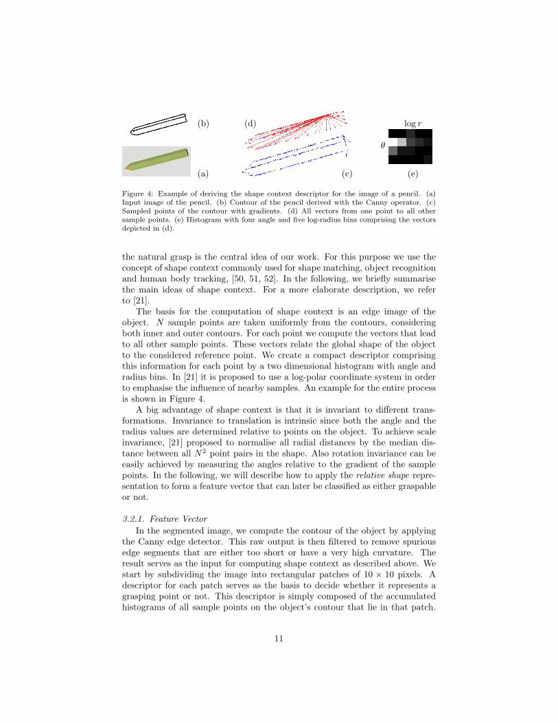
Figure 4: Example of deriving the shape context descriptor for the image of a pencil. (a)Input image of the pencil. (b) Contour of the pencil derived with the Canny operator. (c)Sampled points of the contour with gradients. (d) All vectors from one point to all othersample points. (e) Histogram with four angle and five log-radius bins comprising the vectorsdepicted in (d).
the natural grasp is the central idea of our work. For this purpose we use theconcept of shape context commonly used for shape matching, object recognitionand human body tracking, [50, 51, 52]. In the following, we briefly summarisethe main ideas of shape context. For a more elaborate description, we referto [21].
The basis for the computation of shape context is an edge image of theobject. N sample points are taken uniformly from the contours, consideringboth inner and outer contours. For each point we compute the vectors that leadto all other sample points. These vectors relate the global shape of the objectto the considered reference point. We create a compact descriptor comprisingthis information for each point by a two dimensional histogram with angle andradius bins. In [21] it is proposed to use a log-polar coordinate system in orderto emphasise the influence of nearby samples. An example for the entire processis shown in Figure 4.
A big advantage of shape context is that it is invariant to different trans-formations. Invariance to translation is intrinsic since both the angle and theradius values are determined relative to points on the object. To achieve scaleinvariance, [21] proposed to normalise all radial distances by the median dis-tance between all N2 point pairs in the shape. Also rotation invariance can beeasily achieved by measuring the angles relative to the gradient of the samplepoints. In the following, we will describe how to apply the relative shape repre-sentation to form a feature vector that can later be classified as either graspableor not.
3.2.1. Feature Vector
In the segmented image, we compute the contour of the object by applyingthe Canny edge detector. This raw output is then filtered to remove spuriousedge segments that are either too short or have a very high curvature. Theresult serves as the input for computing shape context as described above. Westart by subdividing the image into rectangular patches of 10 × 10 pixels. Adescriptor for each patch serves as the basis to decide whether it represents agrasping point or not. This descriptor is simply composed of the accumulatedhistograms of all sample points on the object’s contour that lie in that patch.
11

Typically only few sample points will be in a 10 × 10 pixel wide window. Fur-thermore, comparatively small shape details that are less relevant for making agrasp decision will be represented in the edge image. We therefore calculate theaccumulated histograms in three different scales centred at the current patch.The edge image of the lowest scale then contains only major edges of the object.The three histograms are concatenated to form the final feature descriptor ofdimension 120.
3.3. Using Feature Vector for Classification
The detection of grasping points applies a supervised classification approachutilizing the feature vector described in the previous section. We examine twodifferent classification methods: a linear one (logistic regression) and a non-linear one (SVMs), [53]. We describe these briefly below.
Logistic Regression. Let gi denote the binary variable for the ith image patch inthe image. It can either carry the value 1 or 0 for being a grasping point or not.The posterior probability for the former case will be denoted as P (gi = 1|Di)where Di is the feature descriptor of the ith image patch. For logistic regression,this probability is modelled as the sigmoid of a linear function of the featuredescriptor:
P (gi = 1|Di) =1
1 + e−wDi(1)
where w is the weight vector of the linear model. These weights are estimatedby maximum likelihood:
w = arg maxw′
∏
i
P (gi = 1|Di, w′) (2)
where here gi and Di are the labels and feature descriptors of our training data,respectively.
Support Vector Machines. SVMs produces arbitrary decision functions in fea-ture space by a linear separation in a space of higher dimension compared to thefeature space. The mapping of the input data into that space is accomplishedby a non-linear kernel function K. In order to obtain the model for the decisionfunction when applying SVMs, we solve the following optimisation problem:
max∑
i
αi −1
2
∑
i,j
αiαjgigjK(Di,Dj) (3)
subject to 0 ≤ αi ≤ C and∑
i αigi = 0 with the solution w =∑Ns
i αigiDi. Asa kernel we have chosen a Radial Basis Function (RBF):
K(Di,Dj) = e−γ||Di−Dj ||2
, γ > 0 and γ =1
2σ2(4)
The two parameters C and σ are determined by a grid search over parameterspace. In our implementation, we are using the package libsvm [54].
12

Figure 5: One example picture for each of the eight object classes used for training along withtheir grasp labels (in yellow). Depicted are a book, a cereal bowl, a white board eraser, amartini glass, a cup, a pencil, a mug and a stapler. The database is adopted from Saxenaet al. [15].
Training Database. For training the different classifiers we will use the databasedeveloped by Saxena et al. [15] containing ca. 12000 synthetic images of eightobject classes depicted along with their grasp labels in Figure 5. One drawbackof the database is that the choice of grasping points is not always consistentwith the object category. As an example, a cup is labelled at two places onits rim but all the points on the rim are equally well suited for grasping. Theeraser is quite a symmetric object. Neither the local appearance nor the relativeshape of its grasping point are discriminative descriptors. This will be furtherdiscussed in Section 4 where our method is compared to that of [15].
3.4. Approximating Object Shape
Shape context provides a compact 2D representation of objects in monocularimages. However, grasping is an inherently three-dimensional process. Our goalis to apply a pinch grasp on the object using a 3D coordinate of the graspingpoint and known position and orientation of the wrist of the robot. In order toinfer the 6D grasp configuration, we integrate 2D grasping point detection withthe 3D reconstruction of the object that results from the segmentation process.
We approach the problem by detecting the dominant plane Πd : Dd = Adx+Bdy+Cdd in the disparity space d = Id(x, y). The assumption is that the objectcan be represented as a constellation of planes in 3D, i.e. a box-like objecthas commonly three sides visible to the camera while for a cylindrical object,the rim or lid generates the most likely plane. We use RANSAC to estimatethe dominant plane hypothesis Πd and we also determine its centroid Md bycalculating the mean over all the points in the plane {(x, y)|e(x, y) > θ} where
e(x, y) = Id(x, y) − (Dd − Adx − Bdy)
Cd
, (5)
the error between estimated and measured disparity of a point, and θ a thresh-old. By using the standard projective equations between image coordinates(x, y), disparity d, camera coordinates (X,Y,Z), baseline b and the focal lengthf
x = fX
Z, y = f
Y
Z, d =
bf
Z, (6)
we can transform Πd into the camera coordinate frame:
ΠC : −Cdbf = AdfX + BdfY − DdZ. (7)
13
The normal of this plane is then defined as
nC = (AC , BC , CC) = (Adf,Bdf,−Dd). (8)
Equations 6 are also used to convert the plane centroid Md from disparity spaceto MC in the camera coordinate frame.
3.5. Generation of Grasp Hypotheses
In the following, we describe how the dominant plane provides the structuralsupport for inferring a full grasp configuration.
3.5.1. 3D Grasping Point
The outputs of the classifier are candidate grasping points in each of thestereo images. These then need to be matched for estimation of their 3D co-ordinates. For this purpose we create a set Bl = {b(i,l)|i = 1 · · ·m} of m
image patches i in the left image representing local maxima of the classifierP (gi = 1|Di) and whose adjacent patches in the 8-neighbourhood carry valuesclose to that of the centre patch. We apply stereo matching to obtain the corre-sponding patches Br = {b(i,r)|i = 1 · · ·m} in the right image. Let P (b(i,l)|D(i,l))and P (b(i,r)|D(i,r)) be the probability for each image patch in set Bl and Br
to be a grasping point given the respective feature descriptors D(i,l) or D(i,r).Assuming naıve Bayesian independence between corresponding patches in theleft and right image, the probability P (bi|D(i,l),D(i,r)) for a 3D point bi to bea grasping point is modelled as
P (b(i,l)|D(i,l),D(i,r)) = P (b(i,l)|D(i,l)) × P (b(i,r)|D(i,r)). (9)
As already mentioned in the previous section, the approach vector and wristorientation are generated based on the dominant plane. Therefore, the choiceof the best grasping point is also influenced by the detected plane. For thispurpose, we use the error e(b(i,l)) as defined in Equation 5 as a weight wi in theranking of the 3D grasping points. The best patch is then
b = arg maxi
wi × P (b(i,l)|D(i,l),D(i,r)). (10)
3.5.2. Orientation of the Schunk Hand
Given a 3D grasping point b, the dominant plane ΠC with its centroid MC
and normal nC , there are two possibilities for the approach vector a:
(i) a = vC where vC = MC − bΠ and bΠ is the projected grasping point onΠC along nC
(ii) a = nC .
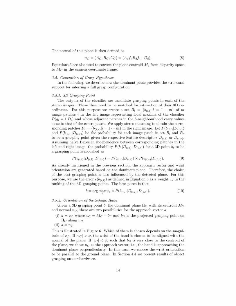
This is illustrated in Figure 6. Which of them is chosen depends on the magni-tude of vC . If |vC | > φ, the wrist of the hand is chosen to be aligned with thenormal of the plane. If |vC | < φ, such that bΠ is very close to the centroid ofthe plane, we chose nC as the approach vector, i.e., the hand is approaching thedominant plane perpendicularly. In this case, we choose the wrist orientationto be parallel to the ground plane. In Section 4.4 we present results of objectgrasping on our hardware.
14
Π
nCMC
bbΠ
a
Gripper
(a) Approach vector ais equal to MC −bΠ. The wrist isaligned with nC .
Π
MC
bbΠ
a = nC
Gripper
φ
(b) Approach Vector a is equalto the normal. The wrist isaligned with the horizon.
Figure 6: Visualisation of the 6 DoF Grasp Configuration with respect to the estimateddominant plane Π
4. Experimental Evaluation
We start by comparing our method to the one presented in [15]. The goal isto show the performance of the methods on synthetic images. This is followedby an in-depth analysis of our method. Finally, we investigate the applicabilityof our method in real settings.
4.1. Evaluation on Synthetic Images
In this section, we are especially interested in how well the classifiers gener-alise over global shape or local appearance given synthetic test images. For thispurpose we applied four different sets of objects to train the classifiers.
• Pencils are grasped at their centre of mass.
• Mugs & cups are grasped at handles. They only differ slightly in globalshape and local grasping point appearance.
• Pencils, white board erasers & martini glasses are all grasped approxi-mately at their centre of mass at two parallel straight edges. However,their global shape and local appearance differ significantly.
• Pencils & mugs are grasped differently and also differ significantly in theirshape.
We divided each set into a training and test set. On the training sets we trainedfour different classifiers.
15

• Shape context & SVM (SCSVM). We employed twelve angle and five logradius bins for the shape context histogram. We sample the contour with300 points. The same parameters were applied by [21] and have proven toperform well for grasping point detection.
• Local appearance features & logistic regression (OrigLog) is the classifierby [15].
• Local appearance features & SVM (OrigSVM) applies an SVM instead oflogistic regression.
• Shape context, local appearance features & SVM (SCOrigSVM) integratesshape context features with local appearance cues. The resulting featurevector is used to train an SVM.
4.1.1. Accuracy
Each model was evaluated on the respective test sets. The results are shownas ROC curves in Figure 7 and as accuracy values in Table 1. Accuracy isdefined as the sum of true positives and true negatives over the total number ofexamples. Table 1 presents the maximum accuracy for a varying threshold.
The first general observation is that SVM classification outperforms logisticregression. On average, the classification performance for each set of objectsrose about 4.32% when comparing OrigSVM with OrigLog. A second generalobservation is that classifiers that employ global shape (either integrated or notintegrated with appearance cues) have the best classification performance forall training sets. In the following we will discuss the results for each set.
• Pencils. The local appearance of a pencil does not vary a lot at differentpositions along its surface whereas the relative shape does. Therefore, lo-cal appearance based features are not discriminative enough. This is con-firmed for the models that are only trained on images of pencils. SCSVMperforms slightly better than OrigSVM. The classification performancegrows when applying an integrated feature vector.
• Mugs & Cups. These objects are grasped at their handle which is charac-terised by a local structure that is rather constant even when the globalshape changes. Thus, OrigSVM outperforms slightly the classifier thatapplies shape context only. However, an integration of both features leadsto an even better performance.
• Pencils, white board erasers & martini glasses. For this set of objectsthe position of the grasp is very similar when considering their globalshape whereas the local appearance of the grasping points differs greatly.Also here, the models based on shape context performs best. Featureintegration degrades the performance.
• Pencils & mugs. The performance of the different classifiers for the pre-vious set of objects is a first indication for a weaker generalisation capa-bility of OrigSVM and OrigLog over varying local appearance compared
16

to SCSVM and SCOrigSVM. This is further confirmed for the last setwhere not just local appearance but also global shape changes signifi-cantly. SCSVM improves the performance of OrigSVM about 6.75% eventhough the grasping points are very different when related to global objectshape. Feature integration increases the performance only moderately.
4.1.2. Repeatability
Our goal is to make a robot grasp arbitrary and novel objects. Thus, weare also interested in if the best grasping point hypotheses correspond to pointsthat in reality afford stable grasps. Thus, our second experiment evaluateswhether the best hypotheses are located on or close to the labelled points. Weconstructed a set of 80 images from the synthetic image database with tenrandomly selected images of each of the eight object classes (Figure 5). Thus,also novel objects that were not used for training the different classifiers areconsidered. On every image we run all the aforementioned models and for eachone picked out the best ten grasping points bi. In the database, a label is nota single point, but actually covers a certain area. We evaluated the Euclideandistance di of each of the ten grasping points measured from the border of thisground truth label at position pj and normalised with respect to the length lj ofits major axis. This way, the distance is dependent on the scale of the object inthe image. In case there is more than one label in the image, we choose the onewith the minimum distance. If a point bi lies directly on the label, the distancedi = 0. If a point lies outside of the label, the distance di gets weighted with aGaussian function (σ = 1, µ = 0) multiplied with
√2π. The number of hits hm
of each model m on the picture set is counted as follows:
hm =
K∑
k=1
Nk∑
i=1
e−d2(i,k)2
with d(i,k) =Mk
minj=1
dist(b(i,k), p(j,k))
2l(j,k)
where K is the number of images in the set, Mk is the number of grasp labels inthat picture and Nk is the number of detected grasping points. Grasping pointswhose distance di exceeds a value of 3 ∗ σ are considered as outliers. Figure 8shows the number of hits, that is, the amount of good grasps for each model.
Apart from the model trained on cups and mugs, the SVM trained onlyon shape context always performs best. The performance drop for the secondobject set can be explained in the same way as in the previous chapter: handleshave a very distinctive local appearance and are therefore easily detected withfeatures that capture this. In general, this result indicates that classifiers basedon shape context detect grasping points with a better repeatability. This isparticularly important for the inference of 3D grasping points in which two2D grasping points in the left and right image of a stereo camera have to bematched.
17

0 0.2 0.4 0.6 0.8 10
0.2
0.4
0.6
0.8
1
OrigLog
OrigSVM
SCSVM
SCOrigSVM
ROC for Pencil Model
0 0.2 0.4 0.6 0.8 10
0.2
0.4
0.6
0.8
1
OrigLog
OrigSVM
SCSVM
SCOrigSVM
ROC for TeaTwo & Mug Model
0 0.2 0.4 0.6 0.8 10
0.2
0.4
0.6
0.8
1
OrigLog
OrigSVM
SCSVM
SCOrigSVM
ROC for Pencil, Martini Glass
& Eraser Model
0 0.2 0.4 0.6 0.8 10
0.2
0.4
0.6
0.8
1
OrigLog
OrigSVM
SCSVM
SCOrigSVM
ROC for Pencil & Mug Model
Figure 7: ROC curves for models trained on different objects.
4.1.3. Summary of Results
We draw several conclusion regarding experimental results on synthetic im-ages. First, independent of which feature representation is chosen, SVM outper-forms logistic regression. Secondly, our simple and compact feature descriptorthat encodes relative object shape improves the detection of grasping pointsboth in accuracy and repeatability in most cases. In case of very distinct localfeatures, both representations are comparable. Integration of the two represen-tations leads only to moderate improvements or even decreases the classificationperformance.
Table 1: Accuracy of the models trained on different objects.
SCOrigSVM SCSVM OrigSVM OrigLog
Pencil 84.45% 82.55% 80.16% 77.07%
Cup & Mug 90.71% 88.01% 88.67% 83.85%
Pencil, Martini
& Eraser 84.38% 85.65% 80.79% 74.92%
Pencil & Mug 85.71% 84.64% 77.80% 74.32%
18

Figure 8: Evaluation of the best ten grasping points of each model on a picture test setcontaining in total 80 pictures of familiar and novel objects (see Figure 5).
4.2. Opening the Black Box
In the previous section, we presented evidence that the shape context basedmodels detect grasping points more accurately than the models trained on localappearance features. As argued in Section 3, we see relative shape as a better cuefor graspability than local appearance. In this section, we would like to confirmthis intuition by analysing what the different grasping point models encode.We conduct this analysis by applying the Trepan Algorithm by Craven andShavlik [55] to the learnt classifiers. This algorithm builds a decision tree thatapproximates a concept represented by a given black box classifier. Althoughoriginally proposed for neural networks, Martens et al. [56] showed that it isalso applicable for SVMs.
We use the same sets of objects as mentioned in the previous section. Theextracted trees are binary with leafs that are classifying feature vectors as ei-ther graspable or non-graspable. The decisions at the non-leaf nodes are madebased on either one or more components of the feature vector. We consider eachpositive leaf node as encoding a prototypical visual feature that indicates gras-pability. As previously mentioned, the extracted trees are only approximationsof the actual models learned. Thus, the feature vectors that end up at a specificleaf of the tree will be of three different kinds:
• Ground truth. Features that are graspable according to the ground truthlabels in the database.
• False positives by model. Features that are not graspable according to thelabels but are so according to the classifier.
• False positives by tree. Features that are neither labelled in the databasenor classified by the model to be graspable, but are considered to be soby the tree.
We will analyse these samples separately and also rate the trees by stating theirfidelity and accuracy . Fidelity is a measure of how well the extracted trees
19

approximate the considered models. It states the amount of features vectorswhose classification is compliant with the classification of the approximatedmodel. Accuracy measures the classification rate for either the tree or the modelwhen run on a test set.
The analysis of these samples is conducted using PCA. The resulting eigen-vectors form an orthonormal basis with the first eigenvector representing thedirection of the highest variance, the second one the direction with the secondlargest variance, etc. In the following sections we visualise only those eigenvec-tors whose energy is above a certain threshold and at maximum ten of these.The energy ei of an eigenvector i is defined as
ei =
∑ij=1 λj
∑k
j=1 λj
(11)
where λj is the eigenvalue of eigenvector j with k eigenvectors in total. As athreshold we use θ = 0.9.
The remainder of this section is structured as follows. In Section 4.2.1, wevisualise the prototypical features for the local appearance method by applyingPCA to the samples at positive nodes. In Section 4.2.1 we do the same for therelative shape based representation.
4.2.1. Local Appearance Features
Saxena et al. [15] applied a filter bank to 10 × 10 pixel patches in threespatial scales. The filter bank contains edge, texture (Law’s masks) and colourfilters. In this section, we depict samples of these 10 × 10 pixel patches in thelargest scale. They are taken from every positive node of each tree trained fora specific object set. All feature vectors that end up at one of these positivenodes are used as an input to PCA.
The first set we present consists of images of a pencil (see Figure 5) labelledin its centre of mass. The built tree is rather shallow: it has only four leaf nodesof which one is positive. The decisions on the non-leaf nodes are made based onthe output of the texture filters only. Neither colour nor edge information areconsidered. This means that this part of the feature vector is not necessary toachieve a classification performance of 75.41% (see Table 2). Ten random sam-ples from the positive node are shown in Figure 9(a)-(c) subdivided dependenton whether they are graspable according to the ground truth labels from thedatabase or only according to the model and tree, respectively.
In order to visualise to which visual cues this grasping point models actuallyrespond, we run PCA on the set of feature vectors that ended up at that node.The resulting principal components selected according to Equation 11 are alsodepicted in Figure 9 (a)-(c). Encoded are close-ups of the body of the penciland perspective distortions.
However, the majority of the pencil complies with these components. Be-cause of that, the samples from the set of false positives are very similar to theground truth samples. The appearance of the centre of mass is not that differentfrom the rest of the pencil. This is further clarified by Figure 9 where the false
20
(a) Ground Truth
(b) False Positive by Model
(c) False Positive by Tree
(d)
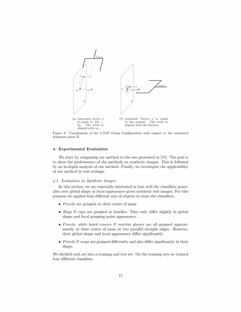
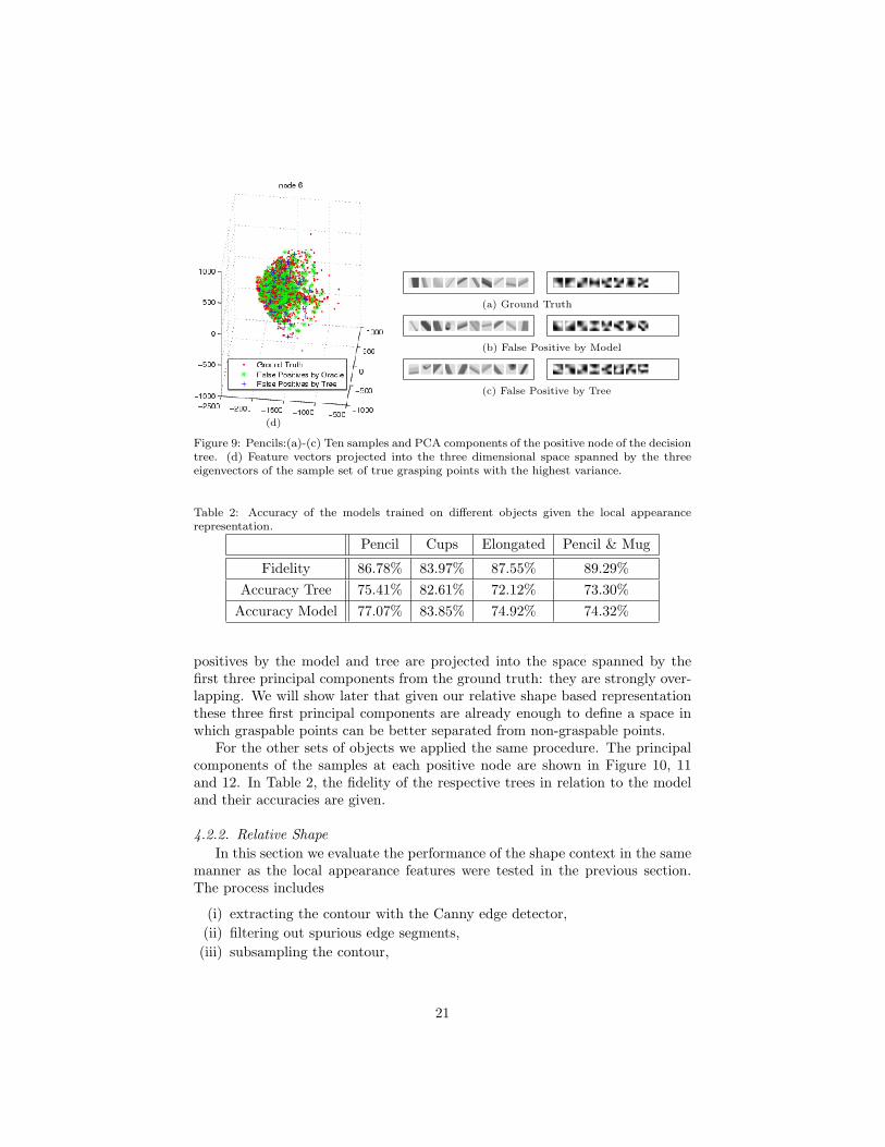
Figure 9: Pencils:(a)-(c) Ten samples and PCA components of the positive node of the decisiontree. (d) Feature vectors projected into the three dimensional space spanned by the threeeigenvectors of the sample set of true grasping points with the highest variance.
Table 2: Accuracy of the models trained on different objects given the local appearancerepresentation.
Pencil Cups Elongated Pencil & Mug
Fidelity 86.78% 83.97% 87.55% 89.29%
Accuracy Tree 75.41% 82.61% 72.12% 73.30%
Accuracy Model 77.07% 83.85% 74.92% 74.32%
positives by the model and tree are projected into the space spanned by thefirst three principal components from the ground truth: they are strongly over-lapping. We will show later that given our relative shape based representationthese three first principal components are already enough to define a space inwhich graspable points can be better separated from non-graspable points.
For the other sets of objects we applied the same procedure. The principalcomponents of the samples at each positive node are shown in Figure 10, 11and 12. In Table 2, the fidelity of the respective trees in relation to the modeland their accuracies are given.
4.2.2. Relative Shape
In this section we evaluate the performance of the shape context in the samemanner as the local appearance features were tested in the previous section.The process includes
(i) extracting the contour with the Canny edge detector,
(ii) filtering out spurious edge segments,
(iii) subsampling the contour,
21
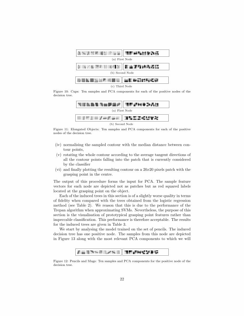
(a) First Node
(b) Second Node
(c) Third Node
Figure 10: Cups: Ten samples and PCA components for each of the positive nodes of thedecision tree.
(a) First Node
(b) Second Node
Figure 11: Elongated Objects: Ten samples and PCA components for each of the positivenodes of the decision tree.
(iv) normalising the sampled contour with the median distance between con-tour points,
(v) rotating the whole contour according to the average tangent directions ofall the contour points falling into the patch that is currently consideredby the classifier
(vi) and finally plotting the resulting contour on a 20x20 pixels patch with thegrasping point in the centre.
The output of this procedure forms the input for PCA. The sample featurevectors for each node are depicted not as patches but as red squared labelslocated at the grasping point on the object.
Each of the induced trees in this section is of a slightly worse quality in termsof fidelity when compared with the trees obtained from the logistic regressionmethod (see Table 2). We reason that this is due to the performance of theTrepan algorithm when approximating SVMs. Nevertheless, the purpose of thissection is the visualisation of prototypical grasping point features rather thanimpeccable classification. This performance is therefore acceptable. The resultsfor the induced trees are given in Table 3.
We start by analysing the model trained on the set of pencils. The induceddecision tree has one positive node. The samples from this node are depictedin Figure 13 along with the most relevant PCA components to which we will
Figure 12: Pencils and Mugs: Ten samples and PCA components for the positive node of thedecision tree.
22

Table 3: Accuracy of the models trained on different objects given the relative shape repre-sentation.
Pencil Cups Elongated Pencil & Mug
Fidelity 78.97% 79.66% 78.79% 80.82%
Accuracy Tree 71.38% 76.89% 73.40% 73.41%
Accuracy Model 82.55% 88.01% 85.56% 84.64%
(a) Ground Truth
(b) False Positives by Model
(c) False Positives by Tree
Figure 13: Pencil: Ten samples and PCA components of the positive node of the decisiontree.
refer in the remainder of this paper as eigencontours. These components donot encode the local appearance but clearly the symmetric relative shape of thegrasping point.
One interesting observation is that the feature vectors projected into thespace spanned by the three best principal components of the ground truth sam-ples are quite well separable, even with a linear decision boundary. There isalmost no overlap between false positives produced by the tree and the groundtruth features and little overlap between false positives produced by the modelsand the true graspable features. This result is shown in Figure 14.
We applied the same procedure to the models trained on the other sets ofobjects. The eigencontours for these are shown in Figs. 15-17. For the setsconsisting of different objects, each positive node in the decision tree is mainlyassociated with one of the objects and encodes where they are graspable.
Furthermore, we can observe a better separability compared to the modelstrained on local appearance. In order to quantify this observation, we analysedthe distribution of the samples in the three-dimensional PCA space in termsof linear separability. As measures for that we employed Fisher’s discriminantratio and the volume of the overlap regions. Figure 14 (b) and (c) show acomparative plot of these two measures for all the models considered in thissection.
4.2.3. Summary of Results
The evaluation provided a valuable insight into different feature representa-tions. We observed that our compact feature descriptor based on relative shapeis more discriminative than the feature descriptor that combines the output of
23

(a)
(b) Fisher’s Discriminant Ratio
(c) Volume of Overlap Region
Figure 14: (a)Pencil: Feature vectors projected into the three dimensional space spanned bythe three eigenvectors of the sample set of true grasping points with the highest variance.(b) and (c) measure linear separability for models trained on different training sets and withdifferent classification methods. Dark: OrigLog. Bright: SCSVM.
(a) First Node
(b) Second Node
(c) Third Node
Figure 15: Cups: Ten samples and PCA components for each of the positive nodes of thedecision tree.
(a) First Node
(b) Second Node
(c) Third Node
Figure 16: Elongated: Ten samples and PCA components for each of the positive nodes ofthe decision tree.
24

(a) First Node
(b) Second Node
(c) Third Node
Figure 17: Pencils and Mugs: Ten samples and PCA components of the first positive node ofthe decision tree.
a filter bank. The dimensionality of our descriptor is almost four times smallerwhich also has implications for the time needed to train an SVM. The classifi-cation performance achieved with an SVM could even be improved by finding adecision boundary in the space spanned by the first three principal componentsof a set of ground truth prototypical features.
4.3. Evaluation on Real Images
In the previous section, we showed that the performance of the relative shapebased classifier is better compared to a method that applies local appearance.In these synthetic images no background clutter was present. However, in a realworld scenario this we need to cope with clutter, occlusions, etc. One exampleis presented in [15]. The authors demonstrated a system for the scenario ofemptying a dishwasher. In order to cope with the visual clutter occurring insuch a scenario, the grasping point model was trained on hand labelled imagesof the dishwasher. Although the dishwasher was emptied successfully, for a newscenario the model has to be re-trained to cope with new backgrounds.
We argue that we need a way to cope with backgrounds based on moregeneral assumptions. As described earlier in Section 3.1, our method relies onscene segmentation. In this section, we evaluate how the relative shape basedrepresentation is affected by different levels of segmentation. For that purpose,we collected images of differently textured and texture-less objects, e.g., boxes,cans, cups, elongated objects, or toys, composed in scenes of different levelsof complexity. This ranges from single objects on a table to several objectsoccluding each other. These scenes were segmented with the three differenttechniques described in Section 3.1.
Ideally, we would like to achieve two things. First is the repeatability: thegrasping points for the same object given different qualities of segmentation haveto match. Second is the robustness: the grasping points should be minimallyaffected by the amount of clutter. Regarding the latter point, a quantitativeevaluation can only be performed by applying the inferred grasps in practise.Thus, we demonstrate our system on real hardware in Section 4.4 and presenthere some representative examples of the grasping point inference methods whenapplied to different kinds of object situated in scenes of varying complexity.
25

4.3.1. Examples for Grasping Point Detection
In Figure 18, we show the results of the grasping point classification fora teapot. The left column shows the segmented input of which the first oneis always the ground truth segment. The middle column shows the result ofthe grasping point classification when applying the local appearance based de-scriptor by [15] and the right one the results of the classification when using therelative shape based descriptor. The red dots label the detected grasping points.They are the local maxima in the resulting probability distribution. Maximallythe ten highest valued local maxima are selected.
The figure shows the grasping point classification when the pot is the onlyobject in the scene and when it is partially occluded. Note that the segmen-tation in the case of local appearance based features is only influencing whichpatches are considered for the selection of grasping points. In case of the rela-tive shape based descriptor, the segmentation also influences the classificationby determining which edge points are included in the shape context represen-tation. Nevertheless, what we can observe is that the detection of graspingpoints for the representation proposed in this paper is quite robust. For exam-ple in Figure 18(b) (last row), even though there is a second handle now in thesegmented region, the rim of the teapot is still detected as graspable and thegeneral resulting grasping point distribution looks similar to the cases in whichthe handle was not yet in the segment. This means, that the object the visionsystem is currently in fixation on, the one that dominates the scene, producesthe strongest responses of the grasping point model even in the presence of othergraspable objects.
In Figure 19(a), we applied the models trained on mugs and cups to imagesof a can and a cup. The descriptor based on local appearance responds verystrongly to textured areas whereas the relative shape based descriptor does notget distracted by that since the whole object shape is included in the graspingpoint inference. Finally in Figure 19(b), we show an example of an object thatis not similar to any object that the grasping point models were trained on. Incase of the local appearance based descriptor, the grasping point probability isalmost uniform and very high valued. In the case of shape context there aresome peaks in the distribution. This suggest that the ability of these modelsto generalise over different shapes is higher than for local appearance basedmodels.
4.3.2. Repeatability of the Detection
One of the goals of the method is the repeatability of grasping point de-tection. In order to evaluate this, we measured the difference of the detectedgrasping points in the differently segmented images. For real images, we do nothave any ground truth labels available as in the case of synthetic data. Thus,we cannot evaluate the grasp quality as was done in Section 4.1. Instead, weuse the detected grasping points in a manually segmented image as a referenceto quantify the repeatability of the grasping point detection.
We have a set B = {bi‖i = 1 . . . N} of pictures and three different cues basedon which they are segmented: zero disparity, a dominant plane and hue. If we
26

want to measure the difference dbibetween the set of grasping points Gbi
={g(bi,j)‖j = 1 . . . M} and the set of reference points Gbi
= {g(bi,r)‖k = 1 . . . R}for a specific kind of segmentation of the image bi, then
dbi=
1
K
M∑
j=1
e−d2
j2 where (12)
dj =R
minr=1
dist(g(bi,r), g(bi,j)) (13)
where dist is the Euclidean distance and K the length of the image diagonal2.The mean and standard deviation of dbi
for all images in the set B that aresegmented with a specific cue is then our measure of deviation of the detectedfrom the reference grasping points.
In Figure 20 we show this measure for a representative selection of objectsand models. As already mentioned, ideally we would like to see no differencebetween detected grasping points when facing different qualities of segmenta-tion. In practise, we can observe a flat slope. As expected for both methods, thegrasping points detected in the image segmented with zero-disparity cues arethe ones that are deviating most from the reference points. Although, the selec-tion of points that are included in our representation is directly influenced bythe segmentation, the difference between detected and reference grasping pointsis not always bigger than for the appearance based method. In fact, sometimesit performs even better. This holds for examples of the models trained on mugsand cups for which both methods show a similar accuracy on synthetic data(Figure 20 (a) and (b)). If the models are applied to novel objects, as can beobserved in Figure 20 (c), our descriptors shows a better repeatability. Thissuggests again a better capability of the models to generalise across differentrelative shapes. In general, we can say that both methods are comparable interms of repeatability.
4.3.3. Summary of Results
In this section, we evaluate the performance of our approach on real images.Due to the encoding of global shape, the method is robust against occlusions andstrong texture. Although our representation is strongly dependent on the seg-mentation, we observe that the repeatability of grasping points is comparableto the local appearance based method even when facing imperfect segmenta-tion. The analysis included images of varying qualities of segmentation as wellocclusion and clutter.
4.4. Demonstration of Real Grasps
In this section we demonstrate the integration of the 2D grasping pointdetection with the minimal 3D object representation as described in Section 3.5.
2In our case K = 80 since we are evaluating 10×10 pixel patches in images of size 640×480pixels
27
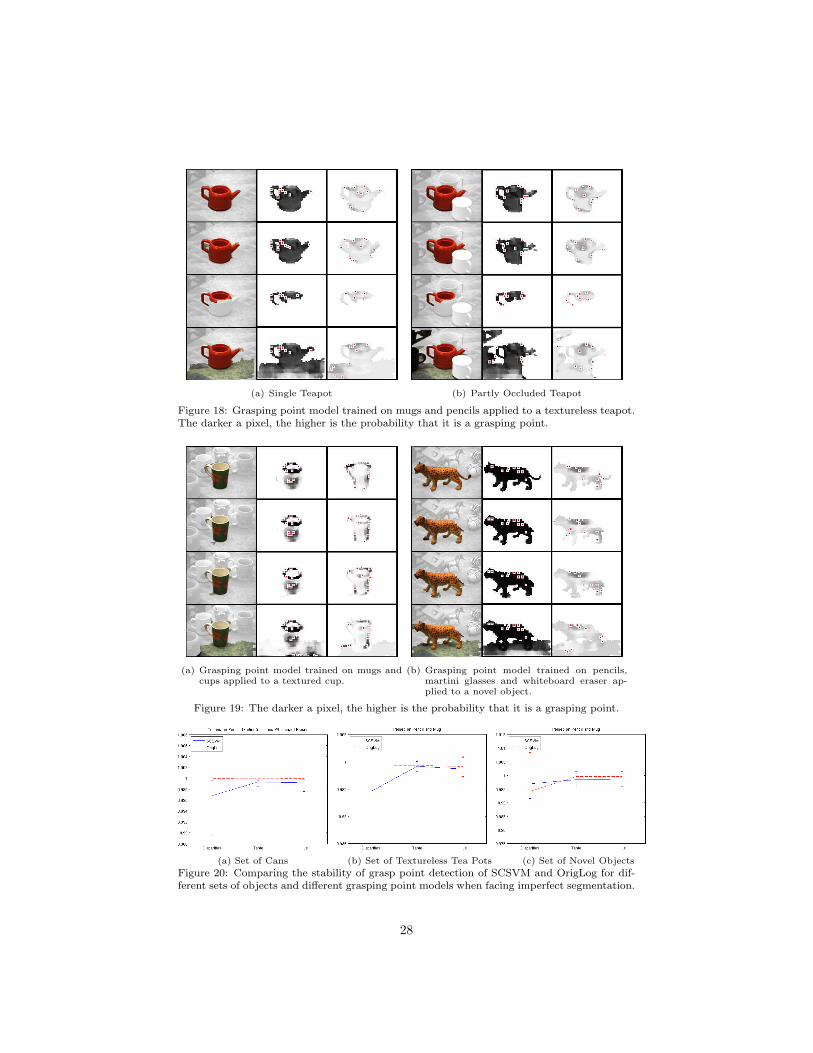
(a) Single Teapot (b) Partly Occluded Teapot
Figure 18: Grasping point model trained on mugs and pencils applied to a textureless teapot.The darker a pixel, the higher is the probability that it is a grasping point.
(a) Grasping point model trained on mugs andcups applied to a textured cup.
(b) Grasping point model trained on pencils,martini glasses and whiteboard eraser ap-plied to a novel object.
Figure 19: The darker a pixel, the higher is the probability that it is a grasping point.
(a) Set of Cans (b) Set of Textureless Tea Pots (c) Set of Novel Objects
Figure 20: Comparing the stability of grasp point detection of SCSVM and OrigLog for dif-ferent sets of objects and different grasping point models when facing imperfect segmentation.
28

We used the hardware setup as depicted in Figure 2(a) and 2(b): a 6 DoFKUKA robotic arm [44], a three-fingered 7 DoF Schunk Hand [45] and the7 DoF Karlsruhe Active Head [30]. In Figure 21, video snapshots from therobot grasping three different objects are given along with the segmented inputimage, inferred grasping point distribution and detected dominant plane 3. Forthis demonstration, we rejected grasping points for which the approach vectorwould result in a collision with the table.
In general, we can observe that the generated grasp hypotheses are reason-able selections from the huge amount of potentially applicable grasps. Failedgrasps are due to the fact that there is no closed-loop control implemented eitherin terms of visual servoing or hand movements as demonstrated in our previouswork [57, 58, 59, 60]. Some grasps also fail due to the slippage or collision.
5. Conclusions
Grasping of unknown objects in natural environments is an important andunsolved problem in the robotic community. In this paper, we have developed amethod for detecting a grasping point on an object by analysing it in a monoc-ular image and reconstructing the suitable 3D grasping representation based ona stereo view . Referring to neuropsychological research mentioned in Section 2,we argued that for the purposes of grasping a yet unseen object, its global shapehas to be taken into account. Therefore, we applied shape context as a visualfeature descriptor that relates the object’s global shape to a single point.
The experimental evaluation was performed both in simulation and in thereal world. The motivation for the simulated experiments was both to compareour approach with some other state of the art approaches as well as to providemore insight into the complexity of the whole modelling process. We showed thata combination of a relative shape based representation and a non-linear classifierleads to an improved performance of the grasping point classification due tobetter discriminativity. Evaluation in the real scene has proven the stability ofthe proposed representation in the presence of clutter. The demonstration ona real robot provides further insight into the difficulty of the object graspingprocess. We see several aspects to be evaluated in the future work. We willcontinue to further develop the method but integrate it more on the stereolevel for generating the grasping point hypotheses. In addition, we will considerother types of representation that take into account several aspects of 2D-3Dinformation. Our ongoing work presented in [61] demonstrates the use of themethod proposed here for grasping unicoloured objects.
Acknowledgement
The authors would like to thank Marten Bjorkman for providing the segmen-tation and Xavi Gratal Martınez for his great help with the hardware system.
3A number of videos can be downloaded from www.csc.kth.se\~bohg.
29

(a) Grasping a Cup - Processed Visual Input
(b) Grasping a Cup - Video Snapshots
(c) Grasping a Sprayer Bottle - Processed Visual Input
(d) Grasping a Sprayer Bottle - Video Snapshots
(e) Grasping a Salt Box - Processed Visual Input
(f) Grasping a Salt Box - Video Snapshot
Figure 21: Generating grasps for different objects: Left: Grasping Point, Projected GraspingPoint and Plane Centroid. Middle: Grasping Point Probabilities. Right: Probabilities ofPixels belonging to the Dominant Plane.
30

This project has been supported by the EU IST-FP7-IP GRASP (2008-2012).
References
[1] M. Goodale, Separate Visual Pathways for Perception and Action, Trendsin Neurosciences 15 (1) (1992) 20–25.
[2] A. Borghi, Grounding Cognition: The Role of Perception and Action inMemory, Language, and Thinking, chap. Object Concepts and Action,Cambridge University Press, 2005.
[3] S. H. Creem, D. R. Proffitt, Grasping Objects by Their Handles: A Nec-essary Interaction between Cognition and Action, Journal of ExperimentalPsychology: Human Perception and Performance 27 (1) (2001) 218–228.
[4] J. Gibson, The Ecological Approach to Visual Perception, Lawrence Erl-baum Associates, 1979.
[5] U. Castiello, M. Jeannerod, Measuring Time to Awareness, Neuroreport2 (12) (1991) 797–800.
[6] M. J. Webster, J. Bachevalier, L. G. Ungerleider, Connections of InferiorTemporal Areas TEO and TE with Parietal and Frontal Cortex in MacaqueMonkeys, Cerebral cortex 4 (5) (1994) 470–483.
[7] S. Ekvall, D. Kragic, Learning and Evaluation of the Approach Vectorfor Automatic Grasp Generation and Planning, in: IEEE InternationalConference on Robotics and Automation, 4715–4720, 2007.
[8] A. Morales, P. Azad, T. Asfour, D. Kraft, S. Knoop, R. Dillmann, A. Kar-gov, C. Pylatiuk, S. Schulz, An Anthropomorphic Grasping Approachfor an Assistant Humanoid Robot, in: 37th International Symposium onRobotics, 149–152, 2006.
[9] J. Glover, D. Rus, N. Roy, Probabilistic Models of Object Geometry forGrasp Planning, in: IEEE International Conference on Robotics and Au-tomation, Pasadena, CA, USA, 2008.
[10] K. Hubner, D. Kragic, Selection of Robot Pre-Grasps using Box-BasedShape Approximation, in: IEEE Int. Conference on Intelligent Robots andSystems, 1765–1770, 2008.
[11] C. Dunes, E. Marchand, C. Collowet, C. Leroux, Active Rough ShapeEstimation of Unknown Objects, in: IEEE International Conference onRobotics and Automation, 3622–3627, 2008.
[12] M. Richtsfeld, M. Vincze, Grasping of Unknown Objects from a Table Top,in: ECCV Workshop on ’Vision in Action: Efficient strategies for cognitiveagents in complex environments’, Marseille, France, 2008.
31

[13] D. Kraft, N. Pugeault, E. Baseski, M. Popovic, D. Kragic, S. Kalkan,F. Worgotter, N. Krueger, Birth of the Object: Detection of Objectnessand Extraction of Object Shape through Object Action Complexes, Inter-national Journal of Humanoid Robotics 5 (2) (2008) 247–265.
[14] G. M. Bone, A. Lambert, M. Edwards, Automated Modelling and RoboticGrasping of Unknown Three-Dimensional Objects, in: IEEE InternationalConference on Robotics and Automation, Pasadena, CA, USA, 292–298,2008.
[15] A. Saxena, J. Driemeyer, J. Kearns, A. Y. Ng, Robotic Grasping of NovelObjects, Neural Information Processing Systems 19 (2007) 1209–1216.
[16] A. Morales, E. Chinellato, A. Fagg, A. del Pobil, Using Experience forAssessing Grasp Reliability, International Journal of Humanoid Robotics1 (4) (2004) 671–691.
[17] M. Stark, P. Lies, M. Zillich, J. Wyatt, B. Schiele, Functional Object ClassDetection Based on Learned Affordance Cues, in: 6th International Con-ference on Computer Vision Systems, vol. 5008 of LNAI, Springer-Verlag,435–444, 2008.
[18] M. A. Goodale, J. P. Meenan, H. H. Bulthoff, D. A. Nicolle, K. J. Murphy,C. I. Racicot, Separate Neural Pathways for the Visual Analysis of ObjectShape in Perception and Prehension, Current Biology 4 (7) (1994) 604–610.
[19] R. H. Cuijpers, J. B. J. Smeets, E. Brenner, On the Relation BetweenObject Shape and Grasping Kinematics, Journal of Neurophysiology 91(2004) 2598–2606.
[20] M. Gentilucci, Object Motor Representation and Reaching-Grasping Con-trol, Neuropsychologia 40 (8) (2002) 1139–1153.
[21] S. Belongie, J. Malik, J. Puzicha, Shape Matching and Object Recogni-tion Using Shape Contexts, IEEE Trans. on Pattern Analysis and MachineIntelligence 24 (4) (2002) 509–522.
[22] J. Speth, A. Morales, P. J. Sanz, Vision-Based Grasp Planning of 3D Ob-jects by Extending 2D Contour Based Algorithms, in: IEEE/RSJ Interna-tional Conference on Intelligent Robots and Systems, 2240–2245, 2008.
[23] V.-D. Nguyen, Constructing stable grasps, International Journal onRobotics Research 8 (1) (1989) 26–37.
[24] K. Shimoga, Robot Grasp Synthesis Algorithms: A Survey, InternationalJournal of Robotic Research 15 (3) (1996) 230–266.
[25] A. T. Miller, S. Knoop, H. I. Christensen, P. K. Allen, Automatic GraspPlanning Using Shape Primitives, in: IEEE Int. Conf. on Robotics andAutomation, 1824–1829, 2003.
32

[26] C. Goldfeder, P. K. Allen, C. Lackner, R. Pelossof, Grasp Planning ViaDecomposition Trees, in: IEEE International Conference on Robotics andAutomation, 4679–4684, 2007.
[27] M. Ciorcarlie, C. Goldfeder, P. Allen, Dexterous Grasping via Eigengrasps:A Low-Dimensional Approach to a High-Complexity Problem, Robotics:Science and Systems Manipulation Workshop .
[28] C. Borst, M. Fischer, G. Hirzinger, Grasping the Dice by Dicing the Grasp,in: IEEE/RSJ International Conference on Intelligent Robots and Systems,3692–3697, 2003.
[29] Y. Li, N. Pollard, A Shape Matching Algorithm for Synthesizing HumanlikeEnveloping Grasps, Humanoid Robots, 2005 5th IEEE-RAS InternationalConference on (2005) 442–449.
[30] T. Asfour, K. Regenstein, P. Azad, J. Schroder, A. Bierbaum,N. Vahrenkamp, R. Dillmann, ARMAR-III: An Integrated Humanoid Plat-form for Sensory-Motor Control, in: 6th IEEE-RAS International Confer-ence on Humanoid Robots, 169–175, 2006.
[31] J. Shotton, J. Winn, C. Rother, A. Criminisi, TextonBoost: Joint Appear-ance, Shape and Context Modeling for Multi-Class Object Recognition andSegmentation, in: Proceedings of European Conference Computer Vision(ECCV), 2006.
[32] V. Ferrari, L. Fevrier, F. Jurie, C. Schmid, Groups of Adjacent ContourSegments for Object Detection, IEEE Trans. Pattern Anal. Mach. Intell.30 (1) (2008) 36–51.
[33] C. Dance, J. Willamowski, L. Fan, C. Bray, G. Csurka, Visual categoriza-tion with bags of keypoints, in: ECCV International Workshop on Statis-tical Learning in Computer Vision, 2004.
[34] F.-F. L., P. Perona, A Bayesian Hierarchical Model for Learning NaturalScene Categories, Computer Vision and Pattern Recognition, IEEE Com-puter Society Conference on 2 (2005) 524–531.
[35] B. Leibe, A. Leonardis, B. Schiele, An Implicit Shape Model for CombinedObject Categorization and Segmentation, in: Toward Category-Level Ob-ject Recognition, 508–524, 2006.
[36] S. Lazebnik, C. Schmid, J. Ponce, Beyond Bags of Features: Spatial Pyra-mid Matching for Recognizing Natural Scene Categories, in: Proc. of theIEEE Conf. on Computer Vision and Pattern Recognition, vol. 2, 2169–2178, 2006.
[37] E. Rosch, C. B. Mervis, W. D. Gray, D. M. Johnson, P. Boyes-Braem, Basicobjects in natural categories, Cognitive Psychology 8 (3) (1976) 382–439.
33

[38] S. El-Khoury, A. Sahbani, Handling Objects By Their Handles, in: IROS-2008 Workshop on Grasp and Task Learning by Imitation, 2008.
[39] R. Pelossof, A. Miller, P. Allen, T. Jebera, An SVM Learning Approachto Robotic Grasping, in: IEEE International Conference on Robotics andAutomation, 3512–3518, 2004.
[40] N. Curtis, J. Xiao, Efficient and Effective Grasping of Novel Objectsthrough Learning and Adapting a Knowledge Base, in: IEEE InternationalConference on Robotics and Automation, 2252–2257, 2008.
[41] J. Grezes, J. Decety, Does Visual Perception of Object Afford Action?Evidence from a Neuroimaging Study., Neuropsychologia 40 (2) (2002) 212–222.
[42] J. Bohg, C.Barck-Holst, K. Hubner, M. Ralph, D. Song, D. Kragic, To-wards Grasp-Oriented Visual Perception in Humanoid Robotics, Interna-tional Journal of Humanoid Robotics 6 (3) (2009) 387–434.
[43] A. Saxena, L. Wong, A. Y. Ng, Learning Grasp Strategies with PartialShape Information, in: 23rd AAAI Conference on Artificial Intelligence,1491–1494, 2008.
[44] KUKA, KR 5 sixx R650, www.kuka-robotics.com, last visited 2009.
[45] SCHUNK, SDH, www.schunk.com, last visited 2009.
[46] M. Bjorkman, D. Kragic, Combination of foveal and peripheral vision forobject recognition and pose estimation, Proceedings IEEE InternationalConference on Robotics and Automation, ICRA’04 5 (2004) 5135 – 5140.
[47] D. Kragic, M. Bjorkman, H. I. Christensen, J.-O. Eklundh, Visionfor robotic object manipulation is domestic settings, Robotics and Au-tonomous Systems (2005) 85–100.
[48] M. Bjorkman, J. Eklundh, Foveated Figure-Ground Segmentation and ItsRole in Recognition, in: British Machine Vision Conference, 2005.
[49] B. Rasolzadeh, A. T. Targhi, J.-O. Eklundh, An Attentional System Com-bining Top-Down and Bottom-Up Influences, in: Workshop on Attentionand Performance in Computational Vision, 123–140, 2007.
[50] K. Grauman, T. Darrell, The pyramid match kernel: discriminative classi-fication with sets of image features, in: Proceedings of IEEE InternationalConference on Computer Vision, vol. 2, 1458–1465, 2005.
[51] C. H. Ek, P. H. Torr, N. D. Lawrence, Gaussian Process Latent VariableModels for Human Pose Estimation, in: 4th Joint Workshop on MultimodalInteraction and Related Machine Learning Algorithms (MLMI 2007), vol.LNCS 4892, Springer-Verlag, Brno, Czech Republic, 132–143, 2007.
34
[52] G. Mori, S. Belongie, J. Malik, S. Member, Efficient shape matching usingshape contexts, IEEE Trans. Pattern Analysis and Machine Intelligence 27(2005) 1832–1837.
[53] C. Bishop, Pattern Recognition and Machine Learning (Information Scienceand Statistics), Springer, 2006.
[54] C.-C. Chang, C.-J. Lin, LIBSVM: A Library for Support vectormachines, software available at http://www.csie.ntu.edu.tw/~cjlin/
libsvm, 2001.
[55] M. Craven, J. Shavlik, Extracting Tree-Structured Representations ofTrained Networks, in: Advances in Neural Information Processing Systems(NIPS-8), MIT Press, 24–30, 1995.
[56] D. Martens, B. Baesens, T. V. Gestel, J. Vanthienen, ComprehensibleCredit Scoring Models using Rule Extraction from Support Vector Ma-chines, European Journal of Operational Research 183 (3) (2007) 1466–1476.
[57] D. Kragic, H. I. Christensen, Cue Integration for Visual Servoing, IEEETransactions on Robotics and Automation 17 (1) (2001) 18–27.
[58] S. Ekvall, D. Kragic, Receptive Field Cooccurrence Histograms for ObjectDetection, in: IEEE/RSJ International Conference on Intelligent Robotsand Systems, IROS’05, 84–89, 2005.
[59] D. Kragic, L. Petersson, H. I. Christensen, Visually guided manipulationtasks, Robotics and Autonomous Systems 40 (2-3) (2001) 193–203.
[60] J. Tegin, S. Ekvall, D. Kragic, B. Iliev, J. Wikander, Demonstration basedLearning and Control for Automatic Grasping, Journal of Intelligent Ser-vice Robotics 2 (1) (2008) 23–30.
[61] N. Bergstrom, J. Bohg, D. Kragic, Integration of Visual Cues for RoboticGrasping, in: Computer Vision Systems, vol. 5815 of Lecture Notes in
Computer Science, Springer Berlin / Heidelberg, 245–254, 2009.
35
Jeannette Bohg holds a M.Sc. in Computer Science from theTechnical University Dresden, Germany and a M.Sc. in AppliedInformation Technology with a focus on Art and Technologyfrom Chalmers in Goteborg, Sweden. Since 2007 she is a Ph.D.candidate in the field of Computer Vision and Robotic Graspingat the department of Computer Science at the Royal Instituteof Technology (KTH).
Danica Kragic received her B.S. degree in mechanical engineer-ing from the Technical University of Rijeka, Croatia, and herPh.D. degree in computer science from the Royal Institute ofTechnology (KTH), Stockholm, Sweden in 1995 and 2001, re-spectively. She is currently a professor in computer science atKTH and chairs the IEEE RAS Committee on Computer andRobot Vision. She received the 2007 IEEE Robotics and Au-tomation Society Early Academic Career Award. Her researchinterests include vision systems, object grasping and manipula-tion and action learning.
36