
Learning About Options in Fiber - Cables Plus USA
53
Including An Introduction Fiber-Optic Basics T ables and T erms Applications LEARNING ABOUT OPTIONS IN FIBER FIBER OPTIONS, INC. / 80 Orville Drive / Bohemia / New York / 11746-2533 516-567-8320 / 1-800-342-3748 / FAX 516-567-8322
Transcript of Learning About Options in Fiber - Cables Plus USA

Including
An Introduction
Fiber-Optic Basics
Tables and Terms
Applications
LEARNING ABOUT
OPTIONS IN FIBER
FIBER OPTIONS, INC. / 80 Orville Drive / Bohemia / New York / 11746-2533516 -567 -8320 / 1 -800 -342 -3748 / FAX 516 -567 -8322
india
Cable Plus USA
india
Cable Plus USA - footer

TABLE OF CONTENTS
SECTION 1
History of Information Transmission .............................................................................................1-1
Advantages/Disadvantages of Fiber ............................................................................................1-1
Light and Reflection and Refraction .............................................................................................1-3
SECTION 2
The Optical Fiber ..........................................................................................................................2-1
The Fiber-Optic Cable ..................................................................................................................2-7
Sources.......................................................................................................................................2-12
Detectors ....................................................................................................................................2-13
Transmitters and Receivers........................................................................................................2-15
Connectors and Splices .............................................................................................................2-17
Couplers and Networks ..............................................................................................................2-25
WDM .......................................................................................................................................2-26
Optical Switch.............................................................................................................................2-27
SECTION 3
Tables .........................................................................................................................................3-1
Glossary of Terms.........................................................................................................................3-5
iRev 10/1994
india
Cable Plus USA
india
Cable Plus USA - footer

HISTORY
The use of light for the transmission of informationis far from a new idea. Paul Revere’s lanterns wereused to signal the approach of the British. And itwas Alexander Graham Bell’s experiments over acentury ago that led to his development of thephotophone, a device that carried speech fromone point to another by means of vibrating mirrorsand a beam of sunlight.
Although never a commercial success, it neverthe-less demonstrated the feasibility of lightwave com-munications. However the technique was shuntedaside and virtually forgotten for almost anotherhundred years.
It probably would have remained in limbo had it notbeen for the appearance of a device called thelaser.
Laser is an acronym for Light Amplification byStimulated Emission of Radiation.
Simply described, the laser is a device that pro-duces a unique kind of radiation — an intenselybright light which can be focused into a narrowbeam of precise wavelength. The tremendousenergies of the laser stem from the fact that it pro-duces what is called coherent light .
The light that comes from a candle or an incan-descent bulb is called incoherent light. It's madeup of many different, relatively short wavelengths(colors) which together appear white. They aresent out in brief bursts of energy at different timesand in different directions. These incoherent lightwaves interfere with each other, thus their energyis weakened, distorted, and diffused.
The laser, on the other hand, emits light wavesthat all have the same wavelength, are in phase,and can be sharply focused to travel in the samedirection over long distances with almost no dis-persion or loss of power.
Lasers provide radiation at optical and infraredfrequencies. With lasers (and associated elec-tronics) it became possible to perform at opticalfrequencies the electronics functions that engi-neers were accustomed to performing at conven-tional radio and microwave frequencies. Thuslasers promised the ability to channel signals withvery high information rates along an extremelynarrow path.
INFORMATION TRANSMISSION
Fiber optics is a relatively new technology thatuses rays of light to send information over hair-thinfibers at blinding speeds. These fibers are usedas an alternative to conventional copper wire in avariety of applications such as those associatedwith security, telecommunications, instrumentationand control, broadcast or audio/visual systems.
Today the ability to transmit huge amounts of infor-mation along slender strands of high-purity glassoptical fiber with the speed of light has revolution-ized communications.
The large signal-carrying capacity of optical fibersmakes it possible to provide not only many more,but much more sophisticated signals than couldever be handled by a comparable amount ofcopper wire.
ADVANTAGES/DISADVANTAGES
The advantages of fiber over copper include:
• Small Size: A 3/8-inch (12 pair) fiber/cableoperating at 140 mb/s can handle as manyvoice channels as a 3-inch diameter copper(900) twisted-pair cable.
• Light Weight: The same fiber-optic cableweighs approximately 132 lbs per kilometer.The twisted pair cable weighs approximately16,000 lbs.
• High Bandwidth: Fiber optics has been band-width tested at over 4-billion bits per secondover a 100 km (60 miles) distance. Theoreticalrates of 50-billion bits are obtainable.
• Low Loss: Current single-mode fibers havelosses as low as .2 dB per km. Multimodelosses are down to 1 dB (at 850 or 1300 nm).This creates opportunities for longer dis-tances without costly repeaters.
• Noise Immunity: Unlike wire systems, whichrequire shielding to prevent electromagneticradiation or pick-up, fiber-optic cable is adielectric and is not affected by electromag-netic or radio frequency interference. Thepotential for lower bit error rates can increasecircuit efficiency.
SECTION 1—INTRODUCTION TO FIBER
1-1
• Transmission Security: Because the fiber is adielectric the fiber does not radiate electro-magnetic pulses, radiation, or other energy thatcan be detected. This makes the fiber/cabledifficult to find and methods to tap into fibercreate a substantial system signal loss.
• No Short Circuits: Since the fiber is glass anddoes not carry electrical current, radiateenergy, or produce heat or sparks, the datais kept within the fiber medium.
• Wide Temperature Range: Fibers and cablescan be manufactured to meet temperaturesfrom -40°F to +200°F. Resistance to tempera-tures of 1,000°F have been recorded.
• No Spark or Fire Hazard: Fiber optics pro-vides a path for data without transmittingelectrical current. For applications in dan-gerous or explosive environments, fiber pro-vides a safe transmission medium.
• Fewer Repeaters: Few repeaters, if any, arerequired because of increased performanceof light sources and continuing increases infiber performance.
• Stable Performance: Fiber optics is affectedless by moisture which means less corrosionand degradation. Therefore, no scheduledmaintenance is required. Fiber also hasgreater temperature stability than coppersystems.
• Topology Compatibility: Fiber is suitable tomeet the changing topologies and configura-tions necessary to meet operation growth andexpansions. Technologies such as wave-length division multiplexing (WDM), opticalmultiplexing, and drop and insert technolo-gies are available to upgrade and recon-figure system designs.
• Decreasing Costs: Costs are decreasing,larger manufacturing volumes, standardiza-tion of common products, greater repeaterspacing, and proven effectiveness of older“paid for” technologies such as multimode.
• Nonobsolescence: Expansion capabilitiesbeyond current technologies using commonfibers and transmission techniques.
• Material Availability: Material (silica glass)required for the production of fiber is readilyavailable in a virtually unending supply.
The few disadvantages of fiber include:
• Cost: Individual components, such as con-nectors, light sources, detectors, cable andtest equipment, may be relatively expensivewhen compared directly to equivalent itemsin a copper system.
• Taps: Drop points must be planned becauseoptical splitters or couplers are much moredifficult to install after the system is in.
• Fear of New Technologies: Because the tech-nology is considered to be new, people arereluctant to change and use these methods.The use of metric and physics is still an unfa-miliar area to may established users.
LIGHT
Light is electromagnetic energy, as are radiowaves, radar, television and radio signals, x-rays,and electronic digital pulses. Electromagneticenergy is radiant energy that travels through freespace at about 300,000/km/s or 186,000 miles/s.
An electromagnetic wave consists of oscillatingelectric and magnetic fields at right angles to eachother and to the direction of propagation. Thus, anelectromagnetic wave is usually depicted as asine wave. The main distinction then between dif-ferent waves lies in their frequency or wavelength.In electronics we customarily talk in terms of fre-quency. In fiber optics, however, light is describedby wavelength. Frequency and wavelength areinversely related.
Electromagnetic energy exists in a continuousrange from subsonic energy through radio waves,microwaves, gamma rays, and beyond. This rangeis known as the electromagnetic spectrum.
It seems to be well understood that glass opticalfiber does not conduct electrons as wire does, orchannel radio-frequency signals as coaxial cabledoes. However, many are unclear about how thelight signals are transmitted and how light acts asa messenger for video, audio, and data over fiber.
1-2
SECTION 1—INTRODUCTION TO FIBER

REFLECTION AND REFRACTION
Optical fiber transmits light by a law of physicsknown as the principle of total internal reflection.This principle was discovered by a British scientistnamed John Tyndall in the mid-1800s. He used itto demonstrate a way to confine light and actuallybend it around corners. His experiments directeda beam of light out through a hole in the side of abucket of water. He was able to demonstrate howthe light was confined to the curved stream ofwater, and how the water’s changing path redi-rected the path of light.
Total internal reflection is even more efficient thanmirrored reflection; it reflects more than 99.9percent of the light.
The quantifiable physical property of a transparentmaterial that relates to total internal reflection is itsrefractive index. Refractive index is defined as theratio of the speed of light in a vacuum to thespeed of light in a specific material.
Light travels fastest through a vacuum. As it startsto travel through denser material, it slows down alittle. What is commonly called the speed of light isactually the velocity of electromagnetic energy in avacuum such as space. Light travels at slowervelocities in other materials such as glass.
Light traveling from one material to anotherchanges speed, which results in light changing itsdirection of travel. This deflection of light is calledrefraction. In addition, different wavelengths oflight travel at different speeds in the same mate-rial. The variation of velocity with wavelength playsan important role in fiber optics.
White light entering a prism contains all colors.The prism refracts the light and it changes speedas it enters. Because each wave changes speeddifferently, each is refracted differently. Red lightdeviates the least and travels the fastest. Violetlight deviates the most and travels the slowest.
The light emerges from the prism divided into thecolors of the rainbow. As can be seen in Figure 1-1refraction occurs at the entrance and at the exit ofthe prism. The amount that a ray of light is refracteddepends on the refractive indices of the two mate-rials. Figure 1-2 illustrates several important termsrequired to understand light and its refraction.
• The normal is an imaginary line perpendicularto the interface of the two materials.
• The angle of incidence is the angle betweenthe incident ray and the normal.
• The angle of refraction is the angle betweenthe refracted ray and the normal.
Light passing from a lower refractive index to ahigher one is bent toward the normal. But lightgoing from a higher index to a lower one refractsaway from the normal, as shown in Figure 1-3.
1-3
Refraction
Refraction Red
Orange
Yellow
Green
Blue
Violet
InterfaceAngle of Refraction
Refracted Ray
ReflectedWave
NormalIncidentRay
Angle ofIncidence
n1n2
is less than n2n1
SECTION 1—INTRODUCTION TO FIBER
Figure 1-1—Refraction and a Prism
Figure 1-2—Angles of Incidence and Refraction

As the angle of incidence increases, the angle ofrefraction of 90° is the critical angle. If the angle ofincidence increases past the critical angle, thelight is totally reflected back into the first materialso that it doesn’t enter the second material. Theangles of incidence and reflection are equal.
Thus:
• Light is electromagnetic energy with a higherfrequency and shorter wavelength than radiowaves.
• Light has both wave-like and particle-like char-acteristics.
• When light meets a boundary separatingmaterials of different refractive indices, it iseither refracted or reflected.
1-4
When the angle of incidence is morethan the critical, light is reflected
n1n2
Angle ofIncidence
Angle ofReflection
=
Angle ofRefraction
Light is bent away from normal
Angle ofIncidence
n1n2
Light does not enter second material
CritialAngle
n1n2
is greater than n2n1
SECTION 1—INTRODUCTION TO FIBER
Figure 1-3—Refraction
india
Cable Plus USA
india
Cable Plus USA - footer

THE OPTICAL FIBER
BASIC FIBER CONSTRUCTION
Optical fiber consists of a thin strand (or core) ofoptically pure glass surrounded by another layerof less pure glass (the cladding). The inner coreis the light-carrying part. The surroundingcladding provides the difference in refractiveindex that allows total internal reflection of lightthrough the core. The index of the cladding is lessthan 1 percent lower than that of the core.
Most fibers have an additional coating around thecladding. This coating, usually one or more layers ofpolymer, protects the core and cladding fromshocks that might affect their optical or physicalproperties. The coating has no optical propertiesaffecting the propagation of light within the fiber.Thus the buffer coating serves as a shock absorber.
Figure 2-1 shows the idea of light traveling througha fiber. Light injected into the fiber and striking thecore-to-cladding interface at greater than the crit-ical angle reflects back into the core. Since theangles of incidence and reflection are equal, thereflected light will again be reflected. The light willcontinue zig zagging down the length of the fiber.
Light, however, striking the interface at less thanthe critical angle passes into the cladding where itis lost over distance. The cladding is usually ineffi-cient as a light carrier, and light in the claddingbecomes attenuated fairly rapidly.
Notice also in Figure 2-1 that the light is refractedas it passes from air into the fiber. Thereafter, its
propagation is governed by the indices of the core and cladding (and by Snell’s law.) Refer to section3, Glossary of Terms, for a definition of Snell’s Law.
The specific characteristics of light propagationthrough a fiber depends on many factors including:The size of the fiber; the composition of the fiber;and the light injected into this fiber. An under-standing of the interplay between these propertieswill clarify many aspects of fiber optics.
Fiber is basically classified into three groups:
• Glass (silica) which includes single-mode stepindex fibers, multimode graded index, andmultimode step index.
• Plastic clad silica (PCS).
• Plastic.
Most optical fibers for telecommunications aremade 99 percent of silica glass, the material fromwhich quartz and sand are formed. Figure 2-1 onthe previous page shows a fiber, which consists ofan inner core (about 8 to 100 micrometers, or0.0003 to 0.004 inches, in diameter), a cladding(125 to 140 micrometers outer diameter) and abuffer jacket for protection.
The clad is made of glass of a slightly differentformula. This causes light entering the core at oneend of the fiber to be trapped inside, a phenom-enon called internal reflection. The light hits theboundary between the core and the claddingbouncing off the cladding much like a billiard balland at the same angle as it travels down the fiber.
2-1
Jacket
Cladding
Core
Cladding
Jacket
Angle of Incidence
Angle of Reflection
Light is propagated by total internal reflection
Light at less than critical angle is absorbed in jacket
Jacket
Core
Cladding
SECTION 2—FIBER-OPTIC BASICS
Figure 2-1—Internal Reflection in an Optical Fiber

Plastic fibers are much larger in diameter and canonly be used for slow-speed, short-distance trans-mission. Plastic-clad silica (PCS) fibers, featuring aglass core with a plastic cladding, come betweenglass and plastic fibers in size and performance.Plastic and PCS fibers cost less than silica glassfibers, but they are also less efficient at transmittinglight. For this reason, they are being used in cars,sensors, and short-distance data-communicationsapplications.
There are other types of fiber emerging on themarketplace, particularly suited for specializeduses. An example would be fluoride fibers whichare being developed for medical and long-haultelecommunications. Medical applications for fiberinclude transmitting power from a laser to destroyarterial blockages or cancer masses. Since fibersare extremely narrow and flexible, they can bethreaded through human arteries to locate precisetrouble areas, and in some cases may eliminatethe need for surgery.
MODE
James Clerk Maxwell, a Scottish physicist in thelast century, first gave mathematical expression tothe relationship between electric and magneticenergy. Mode is a mathematical and physicalconcept describing the propagation of electro-magnetic waves through media. In its mathemat-ical form, mode theory derives from Maxwell’sequations. He showed that they were both a singleform of electromagnetic energy, not two differentforms as was then believed. His equations alsoshowed that the propagation of this energy fol-lowed strict rules.
A mode is simply a path that a light ray can followin traveling down a fiber. The number of modes
supported by a fiber ranges from one to over100,000. Thus a fiber provides a path of travels forone or thousands of light rays, depending on itssize and properties.
REFRACTIVE INDEX PROFILE
This term describes the relationship between theindices of the core and the cladding. Two mainrelationships exist: Step index and graded index.The step-index fiber has a core with a uniformindex throughout. The profile shows a sharp stepat the junction of the core and cladding. In contrast,the graded index has a nonuniform core. The indexis highest at the center and gradually decreasesuntil it matches that of the cladding. There is nosharp break between the core and the cladding.
Step Index
The multimode step-index fiber is the simplesttype. It has a core diameter from 100 to 970 µm,and it includes glass, PCS, and plastic construc-tions. As such, the step-index fiber is the mostwide ranging, although not the most efficient inhaving high bandwidth and low losses.
Graded Index
A graded-index fiber is one where the refractiveindex of the fiber decreases radically towards theoutside of the core. During the manufacturingprocess, multiple layers of glass are deposited onthe preform in a method where the optical indexchange occurs. (Refer Figure 2-3 next page.)
As the light ray travels through the core, thefastest index is the higher or outer area in agraded-index core. (Refer Figure 2-4 next page.)
2-2
Silica Glass Core High Refractive Index
Plastic JacketPlastic Cladding Low Refractive Index
Light
SECTION 2—FIBER OPTIC BASICS
Figure 2-2—Plastic-Clad Silica Fiber
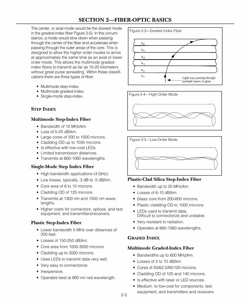
The center, or axial mode would be the slowest modein the graded-index fiber Figure 2-5). In this circum-stance, a mode would slow down when passingthrough the center of the fiber and accelerate whenpassing through the outer areas of the core. This isdesigned to allow the higher order modes to arriveat approximately the same time as an axial or lowerorder mode. This allows the multimode graded-index fibers to transmit as far as 15-20 kilometerswithout great pulse spreading. Within these classifi-cations there are three types of fiber:
• Multimode step-index.• Multimode graded-index.• Single-mode step-index.
STEP INDEX
Multimode Step-Index Fiber• Bandwidth of 10 MHz/km• Loss of 5-20 dB/km.• Large cores of 200 to 1000 microns.• Cladding OD up to 1035 microns.• Is effective with low-cost LEDs• Limited transmission distances.• Transmits at 660-1060 wavelengths.
Single-Mode Step Index Fiber• High bandwidth applications (4 GHz).
• Low losses, typically .3 dB to .5 dB/km.
• Core area of 8 to 10 microns.
• Cladding OD of 125 microns.
• Transmits at 1300 nm and 1550 nm wave-lengths.
• Higher costs for connectors, splices, and testequipment, and transmitters/receivers.
Plastic Step-Index Fiber• Lower bandwidth 5 MHz over distances of
200 feet.
• Losses of 150-250 dB/km.
• Core area from 1000-3000 microns.
• Cladding up to 3000 microns.
• Uses LEDs to transmit data very well.
• Very easy to connectorize.
• Inexpensive.
• Operates best at 660 nm red wavelength.
Plastic-Clad Silica Step-Index Fiber• Bandwidth up to 25 MHz/km
• Losses of 6-10 dB/km.
• Glass core from 200-600 microns.
• Plastic cladding OD to 1000 microns.
• LEDs used to transmit data.Difficult to connectorize and unstable.
• Very resistant to radiation.
• Operates at 660-1060 wavelengths.
GRADED INDEX
Multimode Graded-Index Fiber• Bandwidths up to 600 MHz/km.
• Losses of 2 to 10 dB/km.
• Cores of 50/62.5/85/100 microns.
• Cladding OD of 125 and 140 microns.
• Is effective with laser or LED sources.
• Medium- to low-cost for components, testequipment, and transmitters and receivers.
2-3
Light rays passing through multiple layers of glass
n1
n6
n5
n4
n3
n2
SECTION 2—FIBER-OPTIC BASICS
Figure 2-3—Graded Index Fiber
Figure 2-4—High-Order Mode
Figure 2-5—Low-Order Mode

• Has distance limitations due to higher lossand pulse spreading.
• Transmits at 820-850 nm, 1300 nm, and 1550nm wavelengths.
• Easy to splice and connectorize.
MULTIMODE AND SINGLE-MODE FIBER
Two general types of fiber have emerged to meetuser requirements: multimode and single mode.Inoptical terminology, “mode” can be thought of asa ray of light.
In multimode fiber many modes, or rays, are trans-mitted, whereas in single-mode fiber only onemode of light can travel in the core. Refer to Figure2-6 where the core diameters of these two types offiber have been compared to the diameter of asingle human hair.
Multimode
Multimode fiber’s larger core (diameter in the 50-µm to more than 1000-µm range) captures hun-dreds of rays from the light source, entering thecore at many different angles. Some of these raysexceed the critical angle of incidence and are lostwithout penetrating the fiber.
Of the rays that are captured by the core, sometravel a direct path parallel to the length of thefiber. Modes that enter at a steeper angle travel alonger, circuitous route, crisscrossing the core’sdiameter as they travel down the fiber. Because ofthese different routes, some parts of the light pulsereach the far end sooner than other parts of thesame light pulse.
These differences result in pulse broadening (orspreading) which requires more space betweenpulses, thereby limiting the speed at which pulsescan be introduced into the fiber, and limiting thebandwidth or information-carrying capacity of mul-timode fiber.
Multimode fibers were developed first, and theyhave been installed in many long-distance tele-communications systems. In the past few years,however, single-mode technology has improved tothe point where these smaller fibers are made aseasily and as cheaply as multimode fibers.
Multimode fiber’s significantly larger core (more thanfive times the diameter of a single-mode core) hascertain advantages. It is easier to align core regionsfor splicing and for attaching connectors, and it cap-tures more light from lower cost sources, such asfrom LEDs rather than lasers. Thus multimode isusually preferred for systems that have many con-nectors or joints, and where distance or capacity isnot a factor.
Further, methods can be devised for increasingmultimode fiber’s information-carrying capacity,such as transmitting on multiple wavelengths oflight. This technique is known as wavelength divi-sion multiplexing or WDM.
Single-Mode
Single-mode fiber overcomes the bandwidth short-comings of multimode. Single-mode fiber has amuch smaller core diameter (typically 8 µm to 10µm) allowing a very narrow beam from a singlesource to pass through it with a minimum of pulsedispersion. The cladding diameter, however,
2-4
SECTION 2—FIBER-OPTIC BASICS
Core
8 µm
125 µm
Cladding
Core50 µm
125 µm
Cladding
75 µm
Figure 2-6—Core Diameter of Fiber
Human Hair
Multimode
Single Mode
india
Cable Plus USA

remains at the industry standard of 125 micronsfor purposes of connecting and splicing.
With only one mode it is easier to maintain theintegrity of each light pulse. The pulses can bepacked much more closely together in time, givingsingle-mode fiber much larger channel capacity.
Refer to section 3, References, Tables A and B forcharts offering fiber comparisons.
DISPERSION
Dispersion is the spreading of a light pulse as ittravels down the length of an optical fiber. Dispersionlimits the bandwidth (or information-carrying capacity)of a fiber. There are three main types of dispersion:Modal, material, and waveguide.
Modal Dispersion
Modal dispersion occurs only in multimode fiber.Multimode fiber has a core diameter in the 50-µmto more than 1000-µm range. The large coreallows many modes of light propagation. Sincelight reflects differently for different modes, somerays follow longer paths than others. (Refer topage 2-3, Figures 2-3, 2-4 and 2-5.)
The lowest order mode, the axial ray travelingdown the center of the fiber without reflecting,arrives at the end of the fiber before the higherorder modes that strike the core-to-cladding inter-face at close to the critical angle and, therefore,follow longer paths.
Thus, a narrow pulse of light spreads out as ittravels through the fiber. This spreading of a lightpulse is called modal dispersion. There are threeways to limit modal dispersion:
• Use single-mode fiber since its core diameteris small enough that the fiber propagates onlyone mode efficiently.
• Use a graded-index fiber so that the light raysthat follow longer paths also travel at a fasteraverage velocity and thereby arrive at theother end of the fiber at nearly the same timeas rays that follow shorter paths.
• Use a smaller core diameter, which allowsfewer modes.
Material Dispersion
Different wavelengths (colors) also travel at differentvelocities through a fiber, even in the same mode(refer to earlier discussions on Index of Refraction).Each wavelength, however, travels at a differentspeed through a material, so the index of refrac-tion changes according to wavelength. This phe-nomenon is called material dispersion since itarises from the material properties of the fiber.
Material dispersion is of greater concern in single-mode systems. In multimode systems, modal dis-persion is usually significant enough that materialdispersion is not a problem
Waveguide Dispersion
Waveguide dispersion, most significant in a single-mode fiber, occurs because optical energy travelsat slightly different speeds in the core andcladding. This is because of the slightly differentrefractive indices of the materials.
Altering the internal structure of the fiber allowswaveguide dispersion to be substantiallychanged, thus changing the specified overall dis-persion of the fiber.
BANDWIDTH VS. DISPERSION
Manufacturers of multimode offerings frequentlydo not specify dispersion, rather they specify ameasurement called bandwidth (which is given inmegahertz/kilometers).
For example, a bandwidth of 400 MHz/km meansthat a 400-MHz signal can be transmitted for 1 km.It also means that the product of the frequencyand the length must be 400 or less (BW x L =400). In other words, you can send a lower fre-quency a longer distance: 200 MHz for 2 km; 100MHz for 4 km; or 50 MHz for 8 km.
Conversely, a higher frequency can be sent ashorter distance: 600 MHz for 0.66 km; 800 MHzfor 0.50 km; or 1000 MHz for 0.25 km
Single-mode fibers, on the other hand, are speci-fied by dispersion. This measurement is expressedin picoseconds per kilometer per nanometer ofsource spectral width (ps/km/nm).
In other words, for single-mode fiber dispersion is
2-5
SECTION 2—FIBER-OPTIC BASICS

most affected by the source’s spectral width; thewider the source width (the more wavelengthsinjected into the fiber), the greater the dispersion.
ATTENUATION
Attenuation is the loss of optical power as lighttravels through fiber. Measured in decibels perkilometer, it ranges from over 300 dB/km forplastic fibers to around 0.21 dB/km for single-mode fiber.
Attenuation varies with the wavelength of light. Infiber there are two main causes: Scattering andAbsorption
Scattering
Scattering (Figure 2-7), the more common sourceof attenuation in optical fibers, is the loss of opticalenergy due to molecular imperfections or lack ofoptical purity in the fiber and from the basic struc-ture of the fiber.
Scattering, does just what its name implies. It scat-ters the light in all directions including back to theoptical source. This light reflected back is whatallows optical time domain reflectometers (OTDRs)to measure attenuation levels and optical breaks
Absorption
Absorption (Figure 2-8) is the process by whichimpurities in the fiber absorb optical energy anddissipate it as a small amount of heat, causing thelight to become “dimmer.” The amount convertedto heat, however, is very minor.
Microbend Loss
Microbend loss (Figure 2-9) results from small varia-tions or “bumps” in the core-to-cladding interface.Transmission losses increase due to the fiber radiusdecreasing to the point where light rays begin topass through the cladding boundary. This causesthe fiber rays to reflect at a different angle, thereforecreating a circumstance where higher order modesare refracted into the cladding to escape. As theradius decreases, the attenuation increases.
Fibers with a graded index profile are less sensi-tive to microbending than step-index types. Fiberswith larger cores and different wavelengths canexhibit different attenuation values.
Macrobend Loss
Macrobend losses (Figure 2-10) are caused bydeviations of the core as measured from the axisof the fiber. These irregularities are caused duringthe manufacturing procedures and should not beconfused with microbends.
2-6
SECTION 2—FIBER-OPTIC BASICS
Figure 2-7—Scattering
Figure 2-8—Absorption
Figure 2-9—Microbend
Figure 2-10—Macrobend
NUMERICAL APERTURE
The numerical aperture (NA), or light-gatheringability of a fiber, is the description of the maximumangle in which light will be accepted and propa-gated within the core of the fiber. This angle ofacceptance can vary depending upon the opticalcharacteristics of the indices of refraction of thecore and the cladding.
If a light ray enters the fiber at an angle which isgreater than the NA or critical angle, the ray willnot be reflected back into the core. The ray willthen pass into the cladding becoming a claddingmode, eventually to exit through the fiber surface.The NA of a fiber is important because it gives anindication of how the fiber accepts and propagateslight. A fiber with a large NA accepts light well; afiber with a low NA requires highly directional light.
Fibers with a large NA allow rays to propagate athigher or greater angles. These rays are calledhigher order modes. Because these modes takelonger to reach the receiver, they decrease thebandwidth capability of the fiber and will havehigher attenuation.
Fibers with a lower NA, therefore, transmit lowerorder modes with greater bandwidth rates and lowerattenuation.
Manufacturers do not normally specify NA for single-mode fibers because NA is not a critical parameterfor the system designer or user. Light in a single-mode fiber is not reflected or refracted, so it doesnot exit the fiber at angles. Similarly, the fiber doesnot accept light rays at angles within the NA andpropagate them by total internal reflection. Thus NA,although it can be defined for a single-mode, isessentially meaningless as a practical characteristic.
FIBER STRENGTH
One expects glass to be brittle. Yet, a fiber can belooped into tight circles without breaking. It can alsobe tied into loose knots (pulling the knot tight willbreak the fiber). Tensile strength is the ability of afiber to be stretched or pulled without breaking.
The tensile strength of a fiber exceeds that of asteel filament of the same size. Further, a copperwire must have twice the diameter to have thesame tensile strength as fiber.
As discussed under "Microbend Loss," the maincause of weakness in a fiber is microscopic crackson the surface, or flaws within the fiber. Defectscan grow, eventually causing the fiber to break.
BEND RADIUS
Even though fibers can be wrapped in circles,they have a minimum bend radius. A sharp bendwill snap the glass. Bends have two other effects:
• They increase attenuation slightly. Thiseffect should be intuitively clear. Bendschange the angles of incidence and reflection enough that some high-ordermodes are lost (similarly to microbends).
• Bends decrease the tensile strength of the fiber. If pull is exerted across a bend,the fiber will fail at a lower tensile strengththan if no bend were present.
FIBER-OPTIC CABLE
CABLE CHARACTERISTICS
Fiber-optic cable is jacketed glass fiber. In orderto be usable in fiber-optic systems, the somewhatfragile optical fibers are packaged inside cablesfor strength and protection against breakage, aswell as against such environmental hazards asmoisture, abrasion, and high temperatures.
Packaging of fiber in cable also protects the fibersfrom bending at too sharp an angle, which couldresult in breakage and a consequent loss of signal.
Multiconductor cable is available for all designsand can have as many as 144 fibers per cable. Itis noteworthy that a cable containing 144 fiberscan be as small as .75 inches in diameter.
In addition to the superior transmission capabilities,small size, and weight advantages of fiber-opticcables, another advantage is found in the absenceof electromechanical interference. There are nometallic conductors to induce crosstalk into thesystem. Power influence is nonaffecting, and secu-rity breaches of communications are (at this time)very difficult due to the complexities of tappingoptical fiber.
2-7
SECTION 2—FIBER-OPTIC BASICS

MAIN PARTS OF A FIBER-OPTIC CABLE
The creation of fiber-optic cables involves placingseveral fibers together in a process that involvesuse of strength members and insulated (buffered)conductors. When a number of optical fibers areplaced into a single cable, they are frequentlytwisted around a central passive support (strengthmember) which serves to strengthen the cable.
Although fiber-optic cable comes in many varieties,most have the following elements in common:
• Optical fiber (core and cladding, pluscoating).
• Buffer.
• Strength member.
• Jacket.
Previous sections have dealt with fiber, so only theremaining three items will be dealt with now.
Buffer
Fiber coating, or the buffer, serves three purposes:(1) Protection of the fiber surface from mechanicaldamage; (2) isolation of the fiber from the effects ofmicrobends; and (3) as a moisture barrier.
The outer layer, or secondary coating, is the toughmaterial that protects the fiber surface from mech-anical damage during handling and cabling opera-tions. The inner, or primary coating, is a materialdesigned to isolate the fiber from damage frommicrobending. Both layer obviously serve as mois-ture barriers.
With the exception of abrasion, uncoated fiber is vir-tually unaffected by many environments. Becauseof this, most environmental tests are designed toevaluate coating performance over time.
The simplest buffer is the plastic coating appliedby the fiber manufacturer to the cladding. An addi-tional buffer is added by the cable manufacturer.The cable buffer is one of two types: loose bufferor tight buffer.
The tight buffer design features one or two layersof protective coating placed over the initial fibercoating which may be on an individual fiber basis,or in a ribbon structure. The ribbon design typi-cally features 12 fibers placed parallel betweentwo layers of tape with the ribbons lying looselywithin the cable core.
An advantage to the tight buffer is that it is moreflexible than loose and allows tighter turn radii.This can make tight-tube buffers useful for indoorapplications where temperature variations areminimal and the ability to make tight turns insidewalls is a desirable feature.
The loose buffer design features fibers placed intoa cavity which is much larger than the fiber with itsinitial coating, such as a buffer tube, envelope, orslotted core. This allows the fiber to be slightlylonger than its confining cavity, and allows move-ment of the fiber within the cable to relieve strainduring cabling and field-placing operations.
Individual tight-buffered fiber cables are not gen-erally used in applications subjected to tempera-ture changes due to the added attenuationcaused by the strain that is placed on fiber duringthe cabling process and the contraction differ-ences of the coating material and glass fiberswhen subjected to these changes.
2-8
Black Polyurethane Outer Jacket
Buffer Jacket
Silicone Coating
Strength Members
Cladding (Silica)
Core (Silica)Optical Fiber
SECTION 2—FIBER-OPTIC BASICS
Figure 2-11—Main Parts for a Fiber-Optic Cable
Loose Buffer
Unbuffered Optical Fiber
Tight Buffer
Buffer Layers Applied Directly Over Fiber
Figure 2-12—Loose and Tight Buffers

In loose-buffer tube designs, the fiber tube is usuallyfilled with a viscous gel compound which repelswater. Slotted, or envelope designs are usually filledwith a water-repellent powder. Although water doesnot affect the transmission properties of optical fiber,the formation of ice within the cable will causesevere microbending and added dB loss to thesystem.
A comparison of loose tube features to tight tube isprovided in section 3, Table C.
Strength Member
Strength members add mechanical strength to thefiber. During and after installation, the strengthmembers handle the tensile stresses applied tothe cable so that the fiber is not damaged.
The most common strength members are of Kevlararamid yarn, steel, and fiberglass epoxy rods.Kevlar is most commonly used when individualfibers are placed within their own jackets. Steeland fiberglass members are frequently used inmultifiber cables.
Jacket
The jacket, like wire insulation, provides protectionfrom the effects of abrasion, oil, ozone, acids,alkali, solvents, and so forth. The choice of thejacket material depends on the degree of resis-tance required for different influences and on cost.
A comparison of the relative properties of variouspopular jacket materials is provided in section 3,Table D.
ADDITIONAL CABLE CHARACTERISTICS
Cables come reeled in various lengths, typically1 or 2 km, although lengths of 5 or 6 km are avail-able for single-mode fibers. Long lengths aredesirable for long-distance applications sincecables must be spliced end-to-end over the lengthof the run, hence the longer the cable, the fewerthe splices that will be required.
Fiber coatings or buffer tubes or both are oftencoded to make identification of each fiber easier.In the long-distance link it’s necessary to be ableto ensure that fiber A in the first cable is spliced tofiber A in the second cable, and fiber B to fiber B,and so on.
In addition to knowing the maximum tensile loadsthat can be applied to a cable, it's necessary toknow the installation load. This is the short-termload that the fiber can withstand during the actualprocess of installation. This figure includes theadditional load that is exerted by pulling the fiberthrough ducts or conduits, around corners, etc.The maximum specified installation load will estab-lish the limits on the length of the cable that canbe installed at one time, given the particular appli-cation.
The second load specified is the operating load.During its installed life, the cable cannot withstandloads as heavy as it withstood during installation.The specified operating load is therefore less thanthe installation load. The operating load is alsocalled the static load. For the purposes of this dis-cussion we have divided the discussion on cablesby indoor or outdoor.
2-9
SECTION 2—FIBER-OPTIC BASICS
Simplex
Kevlar Strength Member Outer
Jacket
0.9 [.035]
Buffered Optical Fiber
3.0 [.118]
Kevlar Strength Member
Duplex
0.9 [.035]
Outer Jacket
Kevlar Strength Member
Buffered Optical Fiber
3.0 [.118]
6.1 [.240]
Duplex
0.9 [.035]
Outer Jacket
Buffered Optical Fiber
5.6 [.220]
3.1 [.122]
Figure 2-13—Indoor Cables
Indoor Cable
Cables for indoor applications see Figure 2-13below) include:
• Simplex
• Duplex
• Multifiber
• Undercarpet
• Heavy- and light-duty
• Plenum
Simplex is a term used to indicate a single fiber.Duplex refers to two optical fibers. One fiber maycarry the signals in one direction; the other fiber maycarry the signals in the opposite direction. (Duplexoperation is possible with two simplex cables.)
Physically, duplex cables resemble two simplexcables whose jackets have been bonded together,similar to the jacket of common lamp cords. Thistype of cable is used instead of two simplexcables for aesthetic reasons and for convenience.It’s easier to handle, there’s less chance of the twochannels becoming confused, and the appear-ance is more pleasing.
Multifiber cable, as the name would imply, containmore than two fibers. They allow signals to be dis-tributed throughout a building. Multifiber cablesoften contain several loose-buffer tubes, each con-taining one or more fibers. The use of several tubesallows identification of fibers by tube, since bothtubes and fibers can be color coded.
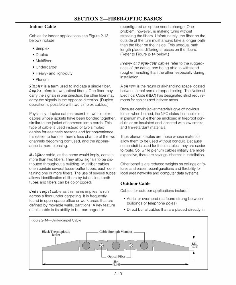
Undercarpet cable,as this name implies, is runacross a floor under carpeting. It is frequentlyfound in open-space office or work areas that aredefined by movable walls, partitions. A key featureof this cable is its ability to be rearranged or
reconfigured as space needs change. Oneproblem, however, is making turns withoutstressing the fibers. Unfortunately, the fiber on theoutside of the turn must always take a longer paththan the fiber on the inside. This unequal pathlength places differing stresses on the fibers.(Refer to Figure 2-14 below.)
Heavy- and light-duty cables refer to the rugged-ness of the cable, one being able to withstandrougher handling than the other, especially duringinstallation.
A plenum is the return or air-handling space locatedbetween a roof and a dropped ceiling. The NationalElectrical Code (NEC) has designated strict require-ments for cables used in these areas.
Because certain jacket materials give off noxiousfumes when burned, the NEC states that cables runin plenum must either be enclosed in fireproof con-duits or be insulated and jacketed with low-smokeand fire-retardant materials.
Thus plenum cables are those whose materialsallow them to be used without conduit. Becauseno conduit is used for these cables, they are easierto route. So, while plenum cables initially are moreexpensive, there are savings inherent in installation.
Other benefits are reduced weights on ceilings or fix-tures and easier reconfigurations and flexibility forlocal area networks and computer data systems.
Outdoor Cable
Cables for outdoor applications include:
• Aerial or overhead (as found strung betweenbuildings or telephone poles).
• Direct burial cables that are placed directly in
2-10
SECTION 2—FIBER-OPTIC BASICS
Black ThermoplasticJacket
1.91 [.075]
29.4 [1.16]
Cable Strength Member
Optical Fiber
Figure 2-14—Undercarpet Cable
a trench dug in the ground and then covered.
• Indirect burial, similar to direct burial, but thecable is inside a duct or conduit.
• Submarine cable is underwater, includingtransoceanic application.
All of the foregoing cables must be rugged anddurable since their applications subject them to avariety of extremes. Typically, the internal glassfiber is the same for all types of fiber cable withsome small exceptions.
Cables designed for underground use may containone or more fibers encased in metal jackets andflooded with a moisture-proofing gel.
Section 3, Table E,offers a chart of ques-tions that should beaddressed whenselecting cables forvarious requirements.
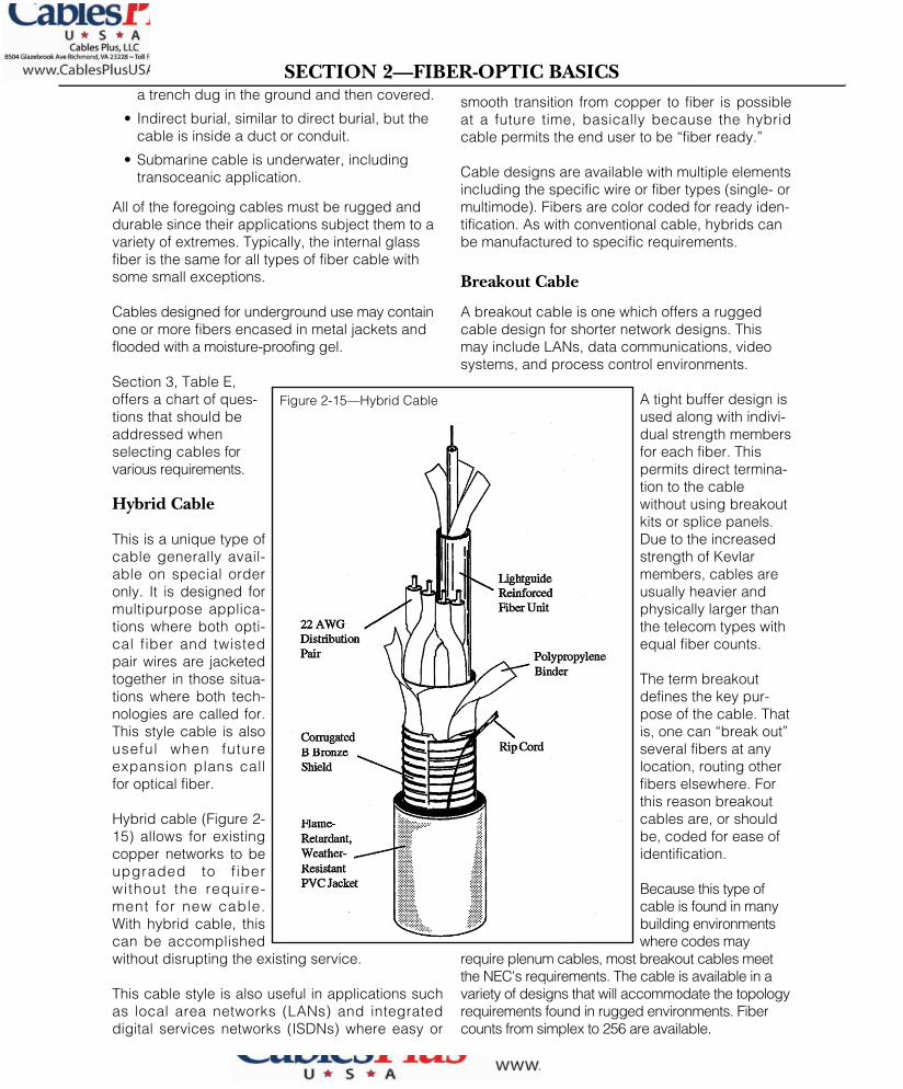
Hybrid Cable
This is a unique type ofcable generally avail-able on special orderonly. It is designed formultipurpose applica-tions where both opti-cal fiber and twistedpair wires are jacketedtogether in those situa-tions where both tech-nologies are called for.This style cable is alsouseful when futureexpansion plans callfor optical fiber.
Hybrid cable (Figure 2-15) allows for existingcopper networks to beupgraded to f iberwithout the require-ment for new cable.With hybrid cable, thiscan be accomplishedwithout disrupting the existing service.
This cable style is also useful in applications suchas local area networks (LANs) and integrateddigital services networks (ISDNs) where easy or
smooth transition from copper to fiber is possibleat a future time, basically because the hybridcable permits the end user to be “fiber ready.”
Cable designs are available with multiple elementsincluding the specific wire or fiber types (single- ormultimode). Fibers are color coded for ready iden-tification. As with conventional cable, hybrids canbe manufactured to specific requirements.
Breakout Cable
A breakout cable is one which offers a ruggedcable design for shorter network designs. Thismay include LANs, data communications, videosystems, and process control environments.
A tight buffer design isused along with indivi-dual strength membersfor each fiber. Thispermits direct termina-tion to the cablewithout using breakoutkits or splice panels.Due to the increasedstrength of Kevlarmembers, cables areusually heavier andphysically larger thanthe telecom types withequal fiber counts.
The term breakoutdefines the key pur-pose of the cable. Thatis, one can “break out”several fibers at anylocation, routing otherfibers elsewhere. Forthis reason breakoutcables are, or shouldbe, coded for ease ofidentification.
Because this type ofcable is found in manybuilding environmentswhere codes may
require plenum cables, most breakout cables meetthe NEC's requirements. The cable is available in avariety of designs that will accommodate the topologyrequirements found in rugged environments. Fibercounts from simplex to 256 are available.
2-11
SECTION 2—FIBER-OPTIC BASICS
Figure 2-15—Hybrid Cable
india
Cable Plus USA
india
Cable Plus USA - footer

CABLE SELECTION
The design and materials used in the cable con-struction selected will depend upon the environ-ment and operation of the user’s application. Thevariables are numerous and they will all have to becarefully weighed.
Refer to section 3, Table E, for a check-off sheetwhich may be copied or adapted for for use whensetting out to determine precisely which cable isbest suited for individual applications. This chartshows many, if not all, of the variables that willhave to be considered throughout this process.
SOURCES
At each end of a fiber-optic link is a device forconverting energy from one form to another. At thesource is an electro-optic transducer, which con-verts an electrical signal to an optical signal. Atthe other end is the optoelectronic transducerwhich converts optical energy to electrical energy.This is discussed further on the next page underDetectors.
SEMICONDUCTOR PN JUNCTION
The semiconductor pn junction is the basic struc-ture used in the electro-optic devices for fiberoptics. Lasers, LEDs, and photodiodes all use thepn junction, as do other semiconductor devicessuch as diodes and transistors.
LASERS AND LEDS
Optical signals begin at the source with lasers orLEDs transmitting light at the exact wavelength atwhich the fiber will carry it most efficiently. Thesource must be switched on and off rapidly andaccurately enough to properly transmit the signals.
Lasers are more powerful and operate at fasterspeeds than LEDs, and they can also transmitlight farther with fewer errors.
LEDs, on the other hand, are less expensive, morereliable, and easier to use than lasers. Lasers areprimarily used in long-distance, high-speed trans-mission systems, but LEDs are fast enough andpowerful enough for short-distance communica-tions, including video communications.
Lasers and LEDs are both semiconductor devicesthat come in the form of tiny chips packaged ineither TO-style cans that plug into printed circuitboard or microlens packages, which focus thebeam into the fiber.
LEDs used in fiber optics are made of materialsthat influence the wavelengths of light that areemitted. LEDs emitting in the window of 820 to 870nm are usually gallium aluminum arsenide(GaAIAs).
“Window,” in this usage, is a term referring toranges of wavelengths matched to the propertiesof the optical fiber. Long wavelength devices foruse at 1300 nm are made of gallium indiumarsenide phosphate (GaInAsP), as well as othercombinations of materials.
Lasers provide stimulated emission rather than thesimplex spontaneous emission of LEDs. The maindifference between a LED and a laser is that thelaser has an optical cavity required for lasing. Thiscavity is formed by cleaving the opposite end ofthe chip to form highly parallel, reflective, mirror-like finishes.
Laser light has the following attributes:
• Nearly monochromatic: The light emitted has a narrow band of wavelengths. It is nearly monochromatic—that is, of a singlewavelength. In contrast to the LED, laser light is not continuous across the band of itsspecial width. Several distinct wavelengths areemitted on either side of the central wavelength.
• Coherent: The light wavelengths are in phase, rising and falling through the sine-wavecycle at the same time.
• Highly directional: The light is emitted in ahighly direction pattern with little diver-gence. Divergence is the spreading of a light beam as it travels from its source.
SOURCE CHARACTERISTICS
Refer to section 3, Table F, for a comparison of themain characteristics of interest for both LED andlaser sources.
2-12
SECTION 2—FIBER-OPTIC BASICS

SPECTRAL WIDTH
Earlier, we discussed material dispersion and thefact that different wavelengths travel through afiber at different velocities. The dispersionresulting from different velocities of different wave-lengths limits bandwidth.
Lasers and LEDs do not emit a single wavelength;they emit a range of wavelengths. This range isknown as the spectral width of the source. It ismeasured at 50 percent of the maximum ampli-tude of the peak wavelength.
DETECTORS
The detector in the fiber-optic system converts theoptical signal into an electrical signal compatiblewith conventional equipment and communicationsnetworks.
A good signal detector responds well to light atthe peak intensity wavelength of the light sourceand fiber combination used (800-900 nanometers,1,000-2,000 nanometers). It also operates with lowinterference, has high reliability, long operatinglife, and small size.
PHOTODIODE BASICS
In moving from the conduction band to the valenceband (the energy bands in semiconductor mate-rial), by recombining electron-hole pairs, an elec-tron gives up energy. In a LED, this energy is anemitted photon of light with a wavelength deter-mined by the band gap separating the two bands.Emission occurs when current from the externalcircuit passes through the LED. With a photodiode,the opposite phenomenon occurs: light falling onthe diode creates current in the external circuit.
Absorbed photons excite electrons from thevalence band to the conduction band, a processknown as intrinsic absorption. The result is the cre-ation of an electron-hole pair. These carriers, underthe influence of the bias voltage applied to thediode, drift through the material and induce acurrent in the external circuit. For each electron-holepair thus created, an electron is set flowing ascurrent in the external circuit. Several types of semi-conductor detectors can be used in fiber-opticsystems — the pn photodiode, the pin photodiode,and the avalanche photodiode.
The pn Photodiode
The simplest device is the pn photodiode. (Referto Figure 2-16.) Two characteristics of this diode,however, make it unsuitable for most fiber-opticapplications.
First, because the depletion area is a relativelysmall portion of the diode’s total volume, many ofthe absorbed photons do not result in externalcurrent. The created hole and free electronsrecombine before they cause external current. Thereceived power must be fairly high to generateappreciable current.
Second, the slow tail response from slow diffusionmakes the diode too slow for medium- and high-speed applications. This slow response limitsoperations to the kilohertz range.
The pin Photodiode
The pin photodiode is designed to overcome thedeficiencies of its pn counterpart. While the pindiode works like the pn diode, it has its peak sen-sitivity to light signals at 1,000-2,000 nanometersin wavelength and can be used with LED sourcesand medium- to high-loss fiber.
The name of the pin diode comes from the layeringof its materials: positive, intrinsic, negative—pin.(Refer to Figure 2-17.) Care must be exercised in
2-13
SECTION 2—FIBER-OPTIC BASICS
n p
Figure 2-16—PN Photodiode
i
n
p+
Figure 2-17—PIN Photodiode

selecting the supplier of this important element ofthe fiber-optic system. It should be understood thata tradeoff exists in arriving at the best pin photo-diode structure and balancing the opposing require-ments to achieve the best balance betweenefficiency and speed.
Avalanche Photodiode
The avalanche photodiode (APD) is morecomplex, consisting of more layers of silicon mate-rial than the pin photodiode. The APD, which wasdeveloped specifically for fiber-optic applications,is efficient across a wider spectrum of light fre-quencies, suffers from less interference, and has afaster response time to signals than the pin photo-diode. It is, however, more expensive as well.
NOISE
Noise (any electrical or optical energy apart fromthe signal itself) is an ever-present phenomenonthat seriously limits the detector’s operation. If thesignal is wanted energy, then noise is anythingelse—that is, unwanted energy.
Although noise can and does occur in every partof the system, it is of greatest concern in thereceiver input because the receiver works withvery weak signals that have been attenuatedduring transmission. An optical signal that is tooweak cannot be distinguished from noise. Todetect such a signal, either the noise level must bereduced or the power level of the signal must beincreased.
An understanding of two types of noise, shot noiseand thermal noise, are important to the under-standing of fiber optics:
Shot Noise
Shot noise arises from the discrete nature of elec-trons. Current is not a continuous, homogeneousflow. It is the flow of individual discrete electrons.
Remember that a photodiode works because anabsorbed photon creates an electron-hole pairthat sets an external electron flowing as current. It is a three-step sequence: photo—electron-holecarriers—electron. The arrival and absorption ofeach photon and the creation of carriers are partof a random process. It is not a perfect homoge-
neous stream, rather it is a series of discreteoccurrences. Therefore, the actual current fluctu-ates as more or less electron holes are created inany given moment. Shot noise occurs even withoutlight falling on the detector.
Thermal Noise
Thermal noise, also called Johnson or Nyquistnoise, arises from fluctuations in the load resis-tance of the detector.
Thermal and shot noise exist in the receiver inde-pendently of the arriving optical power. They resultfrom the very structure of matter. They can be min-imized by careful design of devices and circuits,but they cannot be eliminated. For this reason thesignal must be appreciably larger than the noise inorder to be detected.
As a general rule, the optical signal should betwice the noise current in order to be detected.
SIGNAL-TO-NOISE RATIO
The signal-to-noise ratio (SNR) is a common wayof expressing the quality of signals in a system.SNR is simply the ratio of the average signalpower to the average noise power from all noisesources.
BIT-ERROR RATE
For digital systems, bit-error rate (BER) usuallyreplaces SNR as a measure of system quality.BER is the ratio of incorrectly transmitted bits tocorrectly transmitted bits. A ratio of 10-9 meansthat one wrong bit is received for every one-billionbits transmitted.
DETECTOR CHARACTERISTICS
The characteristics of interest are those that relatemost directly to use in a fiber-optic system. Thesecharacteristics are:
• Responsivity: The ratio of the diode’s outputcurrent to input optical power. It is expressedin amperes/watt (A/W).
• Quantum Efficiency: The ratio of primary elec-tron-hole pairs (created by incident photons) to
2-14
SECTION 2—FIBER-OPTIC BASICS

the photons incident on the diode material).This deals with the fundamental efficiency of thediode for converting photons into free electrons.
• Dark Current: The thermally generated currentin a diode; it is the lowest level of thermal noise.
• Minimum Detectable Power: The minimumpower detectable by the detector determinedthe lowest level of incident optical power thatthe detector can handle.
• Response Time: The time required for the pho-todiode to respond to optical inputs andproduce external current. Usually expressedas a rise time and a fall time, measured in tensof nanoseconds.
TRANSMITTERS AND RECEIVERS
BASIC TRANSMITTER CONCEPTS
The transmitter contains a driver and a source.(Refer to Figure 2-18.) The input to the driver is thesignal from the equipment being served. Theoutput from the driver is the current required tooperate the source.
Most electronic systems operate on standard,well-defined signal levels. Television video signalsuse a 1 volt peak-to-peak level.
Digital systems use different standards, dependingon the type of logic circuits used in the system.These logic circuits define the levels for the highsand lows that represent the 1s and 0s of digitaldata. Digital logic circuits, all further defined underthe Glossary in section 3, are:
• Transistor-transistor logic (TTL) used in manyapplications.
• Emitter-coupled logic (ECL), faster than TTLand not able to be mixed with TTL, it is usually
found in high-speed systems.
• Complementary metal-oxide semiconductor(CMOS), which is rapidly becoming thereplacement for TTL because of its very lowpower consumption.
The drive circuits of the transmitter must acceptsignal input levels, then provide the output currentto drive the source. Characteristics for specifying atransmitter (or a receiver) are basically the same aswould apply for any electronic circuit. These include:
• Power supply voltages
• Storage and operating temperature ranges.
• Required input and output voltage levels(which indicate video, audio, TTL or ECL com-patibility).
• Data rate/bandwidth.
• Operating wavelength.
BASIC RECEIVER CONCEPTS
The receiver contains the detector, amplifier, andoutput circuit. (Refer to Figure 2-19) The amplifieramplifies the attenuated signal from the detector.
The output circuit can perform many functions,such as:
• Separation of the clock and data.
• Pulse reshaping and retiming.
• Level shifting to ensure compatibility—TTL,ECL, and so forth—with the external circuits.
• Gain control to maintain constant levels inresponse to variations in received opticalpower and variations in receiver operationfrom temperature or voltage changes.
Because the receiver deals with highly attenuatedlight signals, it can be considered the principalcomponent around which the design or selection
2-15
SECTION 2—FIBER-OPTIC BASICS
Driver
Source
Figure 2-18—Basic Transmitter Block Diagram
Amplifier
Output Circuit
Detector
Figure 2-19—Basic Receiver Block Diagram
india
Cable Plus USA

of a fiber-optic system revolves. It is in the photo-detector and first stage of amplification that thesignal being transmitted is at its weakest and mostdistorted. It is reasonable to say that this is thecentral part of the link. Thus decisions affectingother parts of the link are made with the receiver inmind. Decisions about the modulation of the trans-mitter are decided, at least in part, by the require-ments of the receiver.
Important receiver characteristics include:
• Power supply voltages
• Storage and operating temperature ranges.
• Required input and output voltage levels(which indicate TTL or ECL compatibility).
• Data rate/bandwidth.
• Sensitivity.
• Dynamic range.
• Operating wavelength.
Sensitivity specifies the weakest optical signal thatcan be received. The minimum signal that can bereceived depends on the noise floor of the receiverfront end.
Dynamic range is the difference between theminimum and maximum acceptable power levels.The minimum level is set by the sensitivity and islimited by the detector. The maximum level is setby either the detector or the amplifier. Power levelsabove the maximum saturate the receiver or distortthe signal. The received optical power must bemaintained below this maximum.
AMPLIFIERS
The two most common designs found in fiber-opticreceivers are low-impedance amplifier and tran-simpedance amplifier. (See Figure 2-20.)
DUTY CYCLE IN THE RECEIVER
The reason for concern for duty cycle in the modu-lation codes is that some receiver designs putrestrictions on the duty cycle. A receiver distin-guishes between high and low pulses by main-taining a reference threshold level. A signal levelabove the threshold is seen as a high or 1; a signallevel below the threshold is seen as a low or 0.Theshifting of threshold level would cause no problems
in an ideal, noiseless receiver. But receivers areneither perfect or noiseless. Signal levels not onlyvary somewhat, but the signals also contain noise.
There are two ways to get around such errors. Thefirst is to maintain a duty cycle close to 50 percent.Manchester and biphase-M codes, by definition,always have a 50 percent duty cycle, so theysatisfy the requirement. Their drawback is that theyrequire a channel bandwidth of twice the data rateand they also increase the complexity of the trans-mitter somewhat.
The second method of avoiding bit errors is todesign a receiver that maintains the thresholdwithout drift. The reference threshold is alwaysmidway between high and low signal levels. Oneway to do this is by a dc-coupled receiver, which isdesigned to operate with arbitrary data streams.The receiver is edge-sensing, meaning that it issensitive to changes in level and not to the levelsthemselves.This type of receiver reacts only topulse transitions.
TRANSCEIVERS AND REPEATERS
A transceiver is a transmitter and a receiver pack-aged together to permit both transmission andreceipt of signals from either station.
A repeater is a receiver driving a transmitter. It'sused to boost signals when the transmission dis-tance is so great that the signal will be too highlyattenuated before it reaches the receiver. Therepeater accepts the signal, amplifies and reshapesit, and feeds the rebuilt signal to a transmitter.
2-16
SECTION 2—FIBER-OPTIC BASICS
Low-Input-ImpedanceAmplifier
Low-Impedance Amplifier Receiver
High-Gain Amplifier
Transimpedance Amplifier Receiver
Figure 2-20—Low- and Transimpedance Amplifiers

CONNECTORS AND SPLICES
The requirements for fiber-optic connection andwire connection are very different. In wiring, twocopper conductors can be joined directly bysolder or by connectors that have been crimpedor soldered to the wires. The purpose is to createcontact between the mated conductors to main-tain a path across the junction.
In fiber-optics, the key to interconnection isprecise alignment of the mated fiber cores (orspots in the case of a single-mode fibers) so thatnearly all of the light is coupled from one fiberacross the junction into the other fiber. Preciseand careful alignment is vital to the success ofsystem operation.
CONNECTOR REQUIREMENTS
Connectors provide the mechanical means for ter-minating optical fibers to other fibers and to activedevices, thereby connecting transmitters, receivers,and cables into working links.
The primary task of the fiber optic connector is tominimize the optical loss across the interface of thecoupled fiber. This loss is expressed in decibels(dB). High-performance connectors are classifiedas those with less than 1 dB of loss; medium perfor-mance is less than 2 dB. Losses occur from inexactmating of the fibers, and the surface condition ofthe fiber ends. (See Figure 2-21.)
The second task of the connector is to providemechanical and environmental protection and sta-bility to the mated junction. Lastly, the connectordesign should permit rapid and uncomplicatedtermination of a cable in a field setting.
An ideal connector would encompass:
• A fiber-alignment scheme yielding low loss.• Physically small.• Rugged construction.• Easily field terminated.• Field repairable.• Good thermal characteristics.• Offer excellent fiber/cable strain relief.• Accessory tooling to prepare fiber and cable.• Factory terminated cable assemblies which
enable users to field connectorize or spliceassemblies using fusion or mechanical splices.
• Be of moderate cost.
CAUSES OF LOSS IN AN INTERCONNECTION
Losses in fiber-optic interconnections are causedby three factors: (1) Intrinsic, or fiber-relatedfactors caused by variations in the fiber itself.; (2)extrinsic, or connector-related factors contributedby the connector itself; or (3) system factors con-tributed by the system itself.
In joining two fibers together it would be nice tosafely assume that the two are identical. However,the fact is that they usually are not. The fiber man-ufacturing process allows fibers to be made onlywithin certain tolerances.
Under section 3, Table G, Intrinsic Loss Factors,lists the most important variations in tolerances thatcause intrinsic loss, i.e., core diameter, claddingdiameter, numerical aperture mismatch, concen-tricity, ellipticity (or ovality) of core or cladding.
Connectors and splices contribute extrinsic loss tothe joint. The loss results from the difficulties inherentin manufacturing a connecting device to the exactingtolerances that are required. The four main causes ofloss that a connector or splice must control are:
• Lateral displacement: A connector shouldalign the fibers on their center axes. When onefiber’s axis does not coincide with that of theother, loss occurs.
2-17
SECTION 2—FIBER-OPTIC BASICS
Figure 2-21—Diameter Mismatch of Connectors
Core
Core 1
Core 2
Cladding
Cladding
Ellipticity (Ovality)
Cladding Diameter Mismatch
Core Diameter Mismatch
Concentricity

• End separation: Two fibers separated by asmall gap will suffer loss.
• Angular misalignment
• Surface roughness.
Again, see Figure 2-21 on the previous page.When two fibers are not perfectly aligned on theircenter axes, lateral displacement loss occurs evenif there is no intrinsic variation in the fiber.
First, the fiber ends must be optically square andsmooth, and second the end-to-end presentationof both fibers must align and the gap (air space)be made minimal. In the case of single-mode con-nectors, the fiber ends may come into contact toreduce the reflective losses.
Two fibers separated by a small gap experienceend-separation loss of two types. First is a Fresnelreflection loss caused by the difference in refrac-tive indices of the two fibers and the interveninggap, which is usually air. The second type of lossfor multimode fibers results from the failure ofhigh-order modes to cross the gap and enter thecore of the second fiber.
Either of these conditions will contribute to loss,the result being dependent on the numerical aper-ture (NA) of the fiber.
A gap between a transmitting and a receiving fiberwill also introduce loss because the air betweenthe fibers is of a different refractive index than thecore of the fibers. With air between the fibers, theFresnel loss would be 0.4 dB. This can be reducedby immersing the junction in a fluid of “matchingliquid,” typically with a refraction index the sameas that of the core. Some connectors use thisfeature, but at the risk of fluid depletion and pos-sible introduction of contaminants.
The ends of mated fibers should be perpendicularto the fiber axes and perpendicular to each other.In order to ensure this, fiber ends are made squareand smooth by one of two methods. These are thelap-and-polish (grind) method and the scribe-and-break (cleave) method. The lap-and-grind methodinvolves the use of a positioning fixture andgrinding/lapping compounds.
Once the ends are square and smooth, the connectordesign must address alignment parameters to ensure
lowest loss. In particular, the connectors must mini-mize fiber lateral offset and angular misalignment.Finally, the fiber face must be smooth and free ofdefects such as hackles, burrs, and fractures.Irregularities from a rough surface disrupt the geo-metrical patterns of light rays and deflect them sothey will not enter the second fiber, thus causingsurface finish loss.
System-related factors can also contribute to lossat a fiber-to-fiber joint. Refer to page 2-6, wherethe subject of dispersion is discussed, and specif-ically describes how modal conditions in a fiberchange with length until the fiber reaches equilib-rium mode distribution (EMD).
Initially, a fiber may be over filled or fully filled withlight being carried both in the cladding and inhigh-order modes. Over distance, these modeswill be stripped away. At EMD, a graded-indexfiber has a reduced NA and a reduced active areaof the core carrying the light.
Consider a connection close to the source. Thefiber on the transmitting side of the connectionmay be over filled. Much of the light in thecladding and high-order modes will not enter thesecond fiber, although it was present at the junc-tion. This same light, however, would not havebeen present in the fiber at EMD, so it would alsonot have been lost at the interconnection point.
Next consider the receiving side of the fiber. Someof the light will spill over the junction into claddingand high-order modes. If the power from a shortlength of fiber were to be measured, these modeswould still be present. But these modes will be lostover distance, so their presence is misleading.
Similar effects will be seen if the connection pointis far from the source where the fiber has reachedEMD. Since the active area of a graded-index fiberhas been reduced, lateral misalignment will notaffect loss as much, particularly if the receivingfiber is short. Again, light will couple into claddingand high-order modes. These modes will be lost ina long receiving fiber.
Thus, the performance of a connector depends onmodal conditions and the connector’s position inthe system. In evaluating a fiber-optic connectoror splice, we must know conditions on both thelaunch (transmitter) side and the receive (receiver)side of the connection.
2-18
SECTION 2—FIBER-OPTIC BASICS
india
Cable Plus USA

Four different conditions exist:
• Short launch, short receive.
• Short launch, long receive.
• Long launch, short receive.
• Long launch, long receive.
LOSS IN SINGLE-MODE FIBERS
It is important to note that connectors and splices forsingle-mode fibers must also provide a high degreeof alignment. In many cases, the percentage of mis-alignment permitted for a single-mode connection isgreater than for its multimode counterpart. Becauseof the small size of the fiber core, however, theactual dimensional tolerances for the connector orsplice remain as tight or tighter.
ALIGNMENT MECHANISMS ANDSPLICE EXAMPLES
Many different mechanisms have been used toachieve the high degree of alignment that isrequired in a connector or splice. Splicing is thename of the process whereby two fibers or cablesare joined together. Fiber splicing consists of:preparation of the fiber; cleaving the fiber; inspec-tion of the cleave; placing of the fibers in an align-ment fixture; alignment or tuning of fibers; bondsplice; inspection and testing; and enclosing ofthe splice for protection.
Basically, there are two types of splices: fusionand mechanical.
FUSION SPLICES
The fusion splice is accomplished by applyinglocalized heating at the interface between twobutted, prealigned fiber ends, causing the fibersto soften and fuse together to form a continuousglass strand. This system offers the lowest lightloss and the highest reliability. Loss should be at.5 dB/splice or less.
Specifically, the fusion splice consists of:
• Joining glass fibers by melting them togetherusing an electric arc.
• Precision controlled for fiber uniformity.
• Permanent, highly reliable, low in cost.
• Average of 50 splices can be done per day inone location by a single team of two persons.
• Typically 0.1 to 0.3 dB loss per splice.
A fusion-splice joint can maintain a breaking strainof more than one percent. This means that suchsplices can be used when manufacturing fiber-optic cable if long, continuous cables of tens ofkilometers are required.
The down side of this method is that training isrequired before using the expensive equipmentthat effects the fusion splice. Depending on thecomplexity of the installation, this may not be thefirst choice.
The fusion-splice process employed can varydepending on the type of splicer used. The twomost common types are the local injection detection(LID) splicer and the manual splicer. Both splicersuse electrodes to melt the fiber ends together.
The LID Splicer
The LID splicer or automatic splicer, is a processthat employs microbending techniques to launchlight into the fiber before the fiber end. On theopposite fiber to be spliced a microbend is againused, but this time with a detector to remove thelaunched light. This allows the processor in thesplicer to align the fiber to where the greatestoptical power level is achieved.
The process for this splicing is positioning the fiberin clamps and alignment fixtures. By activating theautomatic alignment function, the splicer runsthough various X, Y, and Z alignments for opti-mizing the transmission through the two fiber ends.When this is accomplished, the splicer indicatesmaximum alignments and the splicer operator thenfuses the fibers by activating electrodes.
2-19
SECTION 2—FIBER-OPTIC BASICS

The Manual Splicer
A manual splicer usually has two alignment fixtures,each located on one side of the splicer permittingmanual aligning of fiber end through X, Y, and Z axes.
The splicer having prepared each fiber for splicingthen places the fibers in clamps located on eachside of the electrodes. The clamp and alignmentfixtures are then manually manipulated while thesplicer views the process through a microscope.In this process the splicer can inspect the fiberends and the alignment process.
The manual fusion splicer is less expensive thanthe local injection detection splicer and is good formaking multimode splices. Because this unitaligns the fibers on the outer diameter of the fibers,losses can be slightly higher than a LID set whichoptimizes the fiber cores.
It should be noted that because all fibers are notidentical, a good fusion splicer should be easilyadjustable to change arc duration and current tothe electrodes. The reason is that different fiberscan melt or fuse at different temperatures andrequire longer or slower fusion arcs.
Further, when using LID systems, the techniqueallows for optimum core alignment. However, themeasurements obtained from this technique maynot match the OTDR measurements which wouldbe optimized using the same wavelength that thesystem would operate at.
MECHANICAL SPLICE
Mechanical splices are the most straightforward.The installer merely terminates the two ends of thecable that are to be joined and then connectsthem with an inexpensive barrel splice.
This method is fine for short-haul systems, butintroduces light loss of up to 4 dB/splice that maydegrade a system that operates over a distancegreater than two kilometers. It consists of:
• Fibers joined by a glass capillary.
• Splice is permanent, with good reliability andlow loss.
• Average of 50 splices per day in one location.
• Typically 0.1 to 1dB loss per splice (at 850 or1300 nm).
• Can be reusable.
Mechanical splicing methods include rotary,central glass alignment guide (or four-rod), andelastomeric.
The Rotary Splice
The rotary splice (see Figure 2-22 ) is a newermethod of splicing optical fibers. The rotary is botha connector and a splice as it does have thecapability to be mated and unmated like connec-tors, yet has the low attenuation features of anoptical splice. Like optical connectors, this splicetakes longer to terminate, requires more compo-nents, and has a higher component failure rateprior to testing.
Central Glass Alignment Guide Splice
The central glass alignment guide splice uses fourprecision glass rods to precisely align optical fibers.The rods are fused together creating an inner hollowcore. At each end of the splice, the rods are bent ata slight angle allowing the fibers to orient themselvesin the uppermost V groove of the rods. By positioningthe fiber where the ends will be in the middle of thesplice, the fibers can be precisely rotated to allowfor the lowest attenuation.
2-20
SECTION 2—FIBER-OPTIC BASICS
Spring Retainer
LG Fiber Alignment Sleeve LG Fiber
Compression Spring
Ferrule
Figure 2-22—Rotary Splice
india
Cable Plus USA - footer

With the use of splice holders, this type of splice canbe used for temporary splices in both lab and fieldapplications. By using a splice holder, the splice iseasier to work with and has a substantially lowerdiscard rate due to its alignment rod technique.
For permanent installations, the hollow section withthe rods is filled with UV fluid. After aligning thescribed fibers, the splice is cured in minutes byusing a UV lamp. Like all good splices, theprocess requires a good end face to maintain lowattenuation. The advantage of this type of spliceare versatility for field and lab applications and lowtooling costs.
Elastomeric Splice
The elastomeric splice (Figure 2-23) is made froma plastic (elastic) material formed into a mold. Themold allows for a hole to be made. The elas-tomeric material is flexible enough so the fiberscan be positioned and firm enough so the fibersare retained during handling and splicing withoutthe need for positioning equipment.
Because the fibers are mated into the same mold,alignment can be maintained with low attenuation.The fibers can be tuned for low attenuation if careis taken in removing the fibers prior to tuning. Likethe central glass alignment method, the elastomeric
method uses matching fluids or UV fluids dependingon the application. The need for a good scribedoptical fiber will allow for low attenuation measure-ments. A typical elastomeric splice will introducelight loss of less than 1 dB/splice.
FIBER PREPARATION
Proper preparation of the fiber end face is criticalto any fiber-optic connection. The two main fea-tures to be checked for proper preparation areperpendicularity and end finish.
The end face ideally should be perfectly square tothe fiber and practically should be within one or twodegrees of perpendicular. Any divergence beyondtwo degrees increases loss unacceptably. The fiberface should have a smooth, mirrorlike finish freefrom blemishes, hackles, burrs, and other defects.
The two most common methods used to producecorrect end finishes are the cleaving (or scribe-and-break) method and the polish method. Thefirst is used with splices and the second is morecommonly used with connectors.
Whichever method is used, it is necessary to preparea fiber for splicing. To do this the protective jacketsand buffers must be removed to allow access to theoptical fiber. The outer and the inner jackets are
2-21
SECTION 2—FIBER-OPTIC BASICS
Fiber
End Guide
End Guide
Fiber
ElastomerInserts
GlassSleeve
OuterCylindricalSleeve
V-GrooveTemperedEntrance Hole
Insert Parts
Figure 23—Elastomeric Splice

removed, exposing the Kevlar strength member, thebuffer tube, and the fiber. The fiber still has the pro-tective coatings which will also have to be removed.
Standard cable strippers can be used to removethe outer jacketing. The amount of Kevlar removedcan vary depending upon the design of thestrength member of the cable. If the cable doesnot incorporate a strength member, the Kevlar canbe used as such.
The buffer tubes, like the outer jackets, can beremoved by mechanical stripping tools with theoperator taking care not to kink or damage theinternal coated fibers.
Once the coated fiber is exposed, the splicer mustremove the protective coatings to start the actualfiber splicing. Most coated fibers can be strippedusing mechanical or chemical methods. Thesplicer should also take care to use tools or proce-dures that will not damage the fibers.
After the coating is removed, the splicer shouldclean the fiber with Isopropyl alcohol to assure thatthe fiber is clean. Contaminants on fiber can causethe fiber to misalign itself in the alignment fixture.
Cleaving
This is a process which allows the operator tobreak or scribe the fiber with a 90 degree endface perpendicular to the axis of the fiber with littlesurface damage or irregularities to the fiber. (SeeFigure 2-24.)
There are several types of cleavers available foruse in lab or field environments. These vary in priceand performance and should be chosen for the
types of splicing that will be done. When selectingthis tool, keep the following factors in mind:
• Fiber accuracy: The more accurate the tool formaintaining a low angle tolerance, the lowerthe loss will be in the splice.
• Costs: The costs should be in line with the jobto be performed. Don’t spend a thousanddollars on a tool if you’re going to use it in apolish-and-grind optical connector. A majorcost of the tool is the type of blade supplied.Diamond carbide and sapphire blades are themost common, with diamonds rating higherover sapphire.
• Maintenance: Can the tool be calibrated easily?If not, you may need a second tool if your firstone must be sent to the factory for calibrationand/or if the blade must be replaced.
• Amount of fiber exposed: A key factor toremember is how much fiber must be exposedduring the cleave process. The more fiber, themore difficult the stripping process becomes. Atool which requires only a small amount ofexposed fiber and which can be adjusted forlonger lengths is an ideal tool.
Cleaving Methods
Optical fiber is typically cleaved in one of four ways:
• Placing the fiber across a curved surface (againrefer to Figure 24) and bringing the blade downto the fiber. The blade is to scratch the fiber, notcut through it. Slight pressure on manual toolsmay have to be applied. Tools designed for thefibers size will automatically apply the propertension. Once the scratch is made, the fiber will
2-22
SECTION 2—FIBER-OPTIC BASICS
Sapphire
Fiber
Score Here
Slide onEdgeConnector
1˚ - 2˚
Score Deflect
1/16"
1/4" Move and Push
Sapphire
Figure 2-24—Cleaving the Fiber

break due to the curvature of the fiber.
• Placing the fiber in a horizontal fixture wherethe blade will scratch the fiber and the tensionis applied from the end of the fiber pulling thefiber from the scribed location.
• Using a tool which scribes the entire circum-ference of the fiber, and then pulling from theends of the fiber.
• Using a hand scribe or pen scribe where thefiber is placed in the hand or fixture and theoperator draws the scribe tool across the fiber.After the scribe, the operator breaks the fiberoff by tugging with his hand.
Even with the best tools and operator experience, thecleave, scribe, or break can be inadequate. Becauseof this, the end of the cleaved fiber should always beinspected carefully with a field microscope.
Upon inspection, the splicer should look for niceperpendicular end face to the axis of the fiber. No“lips” where the fiber edge is exposed or “hackle”where the fiber has broken away from the fiber. Thefiber should have a good clean end face free ofcracks, chips, and scratches. The angle of the fibershould not be visible. If any of these conditions canbe seen, the cleaving cycle should be repeated.
Polishing
Polishing is done in two or more steps with increas-ingly finer polishing grits. Wet polishing is recom-mended, preferably using water, which not onlylubricates and cools the fiber, but also flushespolish remnants away. The connector and fiberface should be cleaned before switching to a finerpolishing material.
Polishing has a second function: It grinds the con-nector tip to a precise dimension. This dimensioncontrols the depth that the connector tip and fiberextend into the bushing that holds the two connec-tors. It thereby controls the gap between matedfibers. If the tip dimension is too long, the matedfibers may be damaged when they are broughttogether. If the dimension is too short, the gapmay be large enough to produce unacceptablelosses.
The first polishing steps grind the connector tipand fiber to the correct dimension. The final step
polishes the fiber face to a mirrorlike finish.
As with cleaved fiber, polished fiber should beinspected under a microscope. Small scratcheson the fiber face are usually acceptable, as aresmall pits on the outside rim of the cladding, Largescratches, pits in the core region, and fracturesare unacceptable.
Some poor finishes, such as scratches, can beremedied with additional polishing. Fractures andpits, however, usually mean a new connector mustbe installed.
CONNECTOR ASSEMBLY
Ideally one connector type will be used throughoutyour system or network for ease of testing, mainte-nance, and administration. The most commonconnectors found are biconic, ST type and SMA.See Figure 2-25 showing these connector types.
Biconic Connectors
Available in both single- and multimode versions,the biconic is a small size connector with screwthread, cap, and spring-loaded latching mecha-nism. Its advantages are low insertion and returnloss and that it is very common with manufacturersand telephone companies. Its disadvantages are
2-23
ST Type
Biconic
SMA 906
SECTION 2—FIBER-OPTIC BASICS
Figure 2-25— Connector Types
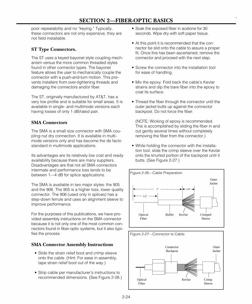
poor repeatability and no “keying.” Typically,these connectors are not only expensive, they arenot field installable.
ST Type Connectors.
The ST uses a keyed bayonet style coupling mech-anism versus the more common threaded stylesfound in other connector types. The bayonetfeature allows the user to mechanically couple theconnector with a push-and-turn motion. This pre-vents installers from over-tightening threads anddamaging the connectors and/or fiber.
The ST, originally manufactured by AT&T, has avery low profile and is suitable for small areas. It isavailable in single- and multimode versions eachhaving losses of only 1 dB/rated pair.
SMA Connectors
The SMA is a small size connector with SMA cou-pling nut dry connection. It is available in multi-mode versions only and has become the de factostandard in multimode applications.
Its advantages are its relatively low cost and readyavailability because there are many suppliers.Disadvantages are that not all SMA connectorsintermate and performance loss tends to bebetween 1—4 dB for splice applications.
The SMA is available in two major styles: the 905and the 906. The 905 is a higher loss, lower qualityconnector. The 906 (used only in splices) has astep-down ferrule and uses an alignment sleeve toimprove performance.
For the purposes of this publications, we have pro-vided assembly instructions on the SMA connectorbecause it is not only one of the most common con-nectors found in fiber-optic systems, but it also typi-fies the process.
SMA Connector Assembly Instructions
• Slide the strain relief boot and crimp sleeveonto the cable. (Hint: For ease in assembly,tape strain relief boot out of the way.)
• Strip cable per manufacturer’s instructions torecommended dimensions. (See Figure 2-26.)
• Soak the exposed fiber in acetone for 30seconds. Wipe dry with soft paper tissue.
• At this point it is recommended that the con-nector be slid onto the cable to assure a properfit. Once this has been ascertained, remove theconnector and proceed with the next step.
• Screw the connector into the installation toolfor ease of handling.
• Mix the epoxy. Fold back the cable’s Kevlarstrains and dip the bare fiber into the epoxy tocoat its surface.
• Thread the fiber through the connector until theouter jacket butts up against the connectorbackpost. Do not force the fiber.
(NOTE: Wicking of epoxy is recommended.This is accomplished by sliding the fiber in andout gently several times without completelyremoving the fiber from the connector.)
• While holding the connector with the installa-tion tool, slide the crimp sleeve over the Kevlaronto the knurled portion of the backpost until itbutts. (See Figure 2-27.)
2-24
SECTION 2—FIBER-OPTIC BASICS
1”
OuterJacket
OpticalFiber
Buffer CrimpedSleeve
Kevlar
1/4”
1/2”
Figure 2-26—Cable Preparation
OpticalFiber
Kevlar CrimpSleeve
ConnectorBackpost
OuterJacket
Figure 2-27—Connector to Cable

• Crimp the sleeve using a crimping tool. (SeeFigure 2-28.)
• Remove the installation tool and apply a beadof epoxy to the front tip of the connector
(NOTE: Take care that epoxy does not get onthe barrel of the connector. If this does occur,clean the connector with Isopropyl alcoholafter the epoxy sets and prior to polishing.)
• Cure the epoxy for approximately 5-10 minutes.
• Using a scribing tool, score the fiber close tothe epoxy bead and gently pull the fiber until itseparates.
• Place lapping film with 15, 3, and 1 micron alu-minum oxide grits on a smooth surface, prefer-ably glass.
(HINT: Leave a portion of the film overhangingthe glass for easy removal.)
• Gently rub the fiber on dry 15 micron film in acircular motion until the fiber is flush with thebead of epoxy.
• Install the connector in the polishing tool.
• Coarse polishing is performed on the 12 micronfilm by moving the polishing tool in a gentlefigure-8 motion while lubricating the film withwater. Progress polishing options to a figureeight pattern and continue for approximatelyone minute or until all epoxy is removed.
• Continue the process on the 3 micron filmapproximately 25-30 figure eight polishing pat-terns on the 1 micron film should produce amirror-like finish. A 5 micron film is recom-mended for an optimum finish.
(NOTE: In order to maintain proper end sepa-ration, the connector must be polished so thatit is flush with the tool. A quick check is toplace the polishing tool with the connector ona flat piece of glass. If any rocking action ispresent, more polishing is needed. Return to 1micron film for additional polishing.)
• Cleaning—Remove the connector from thepolishing tool and rinse both items with waterto remove any fine grit particles.
• Trim the Kevlar close to the crimp sleeve. Thenplace the strain relief boot over the crimpsleeve.
• Inspection—Until experience is gained, thepolished fiber should be inspected under a50X or greater magnification.
• The fiber should possess a mirror-like finishand be flush with the face of the connector.The fiber should be free from most pits,cracks, and scratches.
• Connector should also be cleaned with alcoholor a lens cleaner.
COUPLERS AND NETWORKS
A coupler is a device that will divide light from onefiber into several fibers or, conversely, will couplelight from several fibers in to one.
Important application areas for couplers are in net-works, especially local area networks (LANs), andin wavelength-division multiplexing (WDM).
Networks are composed of a transmission mediumthat connects several nodes or stations. Each nodeis a point at which electronic equipment is con-nected onto the network. The network includes acomplex arrangement of software and hardwarethat ensures compatibility not only of signals butalso of information.
Most important in a network is its logical topology.The logical topology defines the physical andlogical arrangement. The most common logicaltopologies are point-to-point, star, ring, or busstructure. Refer to Figure 2-29 on the next page.
2-25
SECTION 2—FIBER-OPTIC BASICS
OpticalFiber
Connector
KevlarBead ofEpoxy
CrimpedSleeve
OuterJacket
Figure 2-28—Crimping of Ferrule

Point-to-point logical topologies are common intoday’s customer premises installations. Twonodes requiring direct communication are directlylinked by the fibers, normally a fiber pair (one totransmit, one to receive). Common point-to-pointapplications include: computer channel extensions,terminal multiplexing, and video transmission.
An extension of the point-to-point is the logical star.This is a collection of point-to-points, all with acommon node which is in control of the communica-tions system. Common applications include:switches, such as a PBX, and mainframe computers.
The ring structure has each node connected seri-ally with the one on either side of it. Messages flowfrom node to node in one direction only around thering. Examples of ring topologies are: FDDI andIBM’s token ring.
To increase ring survivability in case of a nodefailure, a counter-rotating ring is used. This iswhere two rings are transmitting in opposite direc-tions. It requires two fiber pairs per node ratherthan the one pair used in a simple ring. FDDI uti-lizes a counter-ring topology.
The logical bus structure is supported by emergingstandards, specifically IEEE 802.3. All nodesshare a common line. Transmission occurs in bothdirections on the common line rather than in onedirection as on a ring. When one node transmits,all the other nodes receive the transmission atapproximately the same time. The most popularsystems requiring a bus topology are Ethernet, andMAP, or Manufacturing Automation Protocol.
COUPLER BASICS
A coupler is an optical device that combines orsplits signals travelling on optical fibers. A port isan input or output point for light; a coupler is amultiport device.
A coupler is passive and bidirectional. Becausethe coupler is not a perfect device, excess lossescan occur.
These losses within fibers are internal to thecoupler and occur from scattering, absorption,reflections, misalignments, and poor isolation.Excess loss does not include losses from connec-tors attaching fibers to the ports. Further, sincemost couplers contain an optical fiber at eachport, additional loss can occur because of diam-eter and NA mismatches between the coupler portand the attached fiber.
WAVELENGTH-DIVISION MULTIPLEXING (WDM)Multiplexing is a method of sending severalsignals over a line simultaneously. Wavelength-division multiplexing (WDM) uses different wave-lengths to multiplex two or more signals.
Transmitters operating at different wavelengths caneach inject their optical signals into an optical fiber.At the other end of the link, the signals can again bediscriminated and separated by wavelength. AWDM coupler serves to combine separate wave-lengths onto a single fiber or to split combinedwavelengths back into their component signals.
Two important considerations in a WDM deviceare crosstalk and channel separation. Both are ofconcern mainly in the receiving or demultiplexingend of the system.
Crosstalk
Crosstalk refers to how well the demultiplexedchannels are separated. Each channel shouldappear only at its intended port and not at anyother output port. The crosstalk specificationexpresses how well a coupler maintains this port-to-port separation. Crosstalk, for example, measureshow much of an 820 nm wavelength appears at the1300 nm port. For example: a crosstalk of 20 dBmeans that one percent of the signal appears atthe unintended port.
2-26
SECTION 2—FIBER-OPTIC BASICS
Figure 2-29—Network Topologies
Ring Network
Bus Structure
Star Network

Channel Separation
Channel separation describes how well a couplercan distinguish wavelengths. In most couplers, thewavelengths must be widely separated, such as820 nm and 1300 nm. Such a device will not distin-guish between 1290 nm and 1310 nm signals.
WDM allows the potential information-carryingcapacity of an optical fiber to be increased signifi-cantly.
The bandwidth-length product used to specify theinformation-carrying capacity of a fiber applies onlyto a single channel—in other words, to a signalimposed on a single optical carrier.
OPTICAL SWITCH
It is sometimes desirable to couple light from onefiber to one of two fibers, but not to both. Apassive coupler (described earlier) does not allowsuch a choice. The division of light is always thesame. An optical switch, however, does allowsuch a choice. It is analogous to an electricalswitch, since it permits one of two circuit paths tobe chosen, depending on the switch setting.
When used in a ring network, however, failure of asingle terminal will shut down the entire network.The fiber-optic bypass switch overcomes thisproblem. Two settings on this switch permit thelight signal to be transmitted to the terminalreceiver or to bypass the terminal and continue onthe ring to the next terminal. A directional couplerafter the switch must also be used in conjunctionwith the switch.
The switch uses a relay arrangement to move thefiber between positions. A switch can be con-structed so that it automatically switches to thebypass position if the power is removed, eitherfrom turning off the terminal intentionally or fromunexpected disruption. The result is a certaindegree of “fail-safe” operation.
The drawback to these switches is the difficulty ofmanufacturing low loss switches. Maintainingalignment on moving parts and over repeatedswitchings compounds the already difficult task ofholding the tight tolerances imposed by the needfor precise alignment in fiber optics.
For this reason and many others, great careshould be exercised when selecting the manufac-turer of the fiber-optic system for your application.
2-27
SECTION 2—FIBER-OPTIC BASICS
india
Cable Plus USA - footer

Component Purpose Material
Buffer Jacket
Central Member
Strength Member
Cable Jacket
Armoring (BuriedCable)
Protects fiber from moisture,chemicals and mechanicalstresses that are placed oncable during installation,splicing, and during its lifetime.
Facilitates stranding; allowscable flexing; provides tempera-ture stability; prevents buckling.
Primary tensile loading bearingmember.
Contains and protects cable corefrom scruff, impact crush, mois-ture, chemicals. Flame retardant.
Protects from rodent attack andcrushing forces.
Halar; PolyesterPUR filling com-pound.
Steel or fiberglassepoxy; PE over-coat.
Synthetic yarns(e.g., Kevlar).
Extruded PUR,PVC, PE, Teflon.
Corrugated steeltape.
SECTION 3—REFERENCES
3-1
Core diameter (in µ) 8 50 62.5 85 100
Cladding diameter (in µ) 125 125 125 125 140
Numerical Aperture (NA) 0.11 0.20 0.29 0.26 0.30
Attenuation 850nm N/A 3 4 5 6(dB/km) 1300nm .5 1.75 2 4 5
1550nm .3 N/A N/A N/A N/A
Bandwidth: 850nm N/A 600 230 200 100(MHz/km) 1300nm N/A 750 500 300 300
Primary Coating Layer 250 250.900 250.900 250.900 250.900(in µ)
TABLES
TABLE A—FIBER SPECIFICATIONS
TABLE B—CABLE COMPONENTS
india
Cable Plus USA
india
Cable Plus USA - footer

SECTION 3—REFERENCES
3-2
Loose Tube Features Tight Tube
Heavier
Larger
Larger
Less
Yes
Less
Better
Weight
Size
Diameter
Microbending
Pressurization
Ruggedness
Tensile Loading
Lighter
Smaller
Smaller
Greater
No
More
Worse
Low-Density Cellular High-Density Poly- Poly-PVC Polyethylene Polyethylene Polyethylene propylene urethane Nylon Teflon
Oxidation Resistance E E E E E E E OHeat Resistance G-E G G E E G E OOil Resistance F G G G-E F E E OLow-Temperature Flexibility P-G G-E E E P G G O
Weather, Sun Resistance G-E E E E E G E OOzone Resistance E E E E E E E EAbrasion Resistance F-G F-G F E F-G O E EElectrical Properties F-G E E E E P P EFlame Resistance E P P P P F P ONuclear Radiation Resistance G G G G F G F-G PWater Resistance E E E E E P-G P-F EAcid Resistance G-E G-E G-E G-E E F P-F EAlkali Resistance G-E G-E G-E G-E E F E EGasoline, Kerosene, etc.(Aliphatic Hydrocarbons)Resistance P P-F P-F P-F P-F G G EBenzol, Toluol, etc., (AromaticHydrocarbons) Resistance P-F P P P P-F P G EDegreaser Solvents(Halogenated Hydrocarbons)Resistance P-F P P P P P G EAlcohol Resistance G-E E E E E P P E
P = poor F = fair G = good E = excellent O = outstandingThese ranges are based on average performance of general-purpose compounds. Any given property can usually be improvedby the use of selective compounding.
TABLE C—CABLE COMPARISON (LOOSE TUBE TO TIGHT TUBE)
TABLE D—PROPERTIES OF JACKET MATERIALS
india
Cable Plus USA
india
Cable Plus USA - footer

SECTION 3—REFERENCES
3-3
TABLE F — SOURCE CHARACTERISTICS
TABLE E — CABLE SELECTION
The following questions should be addressed when selecting the cable for your requirement:
Construction: n Hybrid n All Dielectric n Metal Strength Members n Other
Jacket Material: n PVC n Polyurethane n Polyethylene n Other
Environmental Considerations: n Water blocking compounds required. n Rodent Protection
n Flame Retardant n Abrasion Resistant n Nuclear Radiation Resistant n Other
Fiber Features: n Single-mode n Multimode
Numerical Aperture Number of fibers
Core size Cladding OD
Loss (per/km) Bandwidth (MHz/km)
TABLE G — INTRINSIC LOSS FACTORS
Characteristic LED Laser
Output power Lower Higher
Speed Slower Faster
Output pattern (NA) Higher Lower
Spectral width Wider Narrower
Single-mode compatibility Wider Narrower
Ease of use Easier Harder
Cost Lower Higher
Type of Variation Tolerance
Core diameter (50µm) ± 3µnm
Cladding diameter (125µm) ± 3µm
Numerical aperture (0.260) ± 0.015
Concentricity ≤ 3µm
Core ovality > 0.98
Cladding ovality > 0.98
india
Cable Plus USA
india
Cable Plus USA - footer
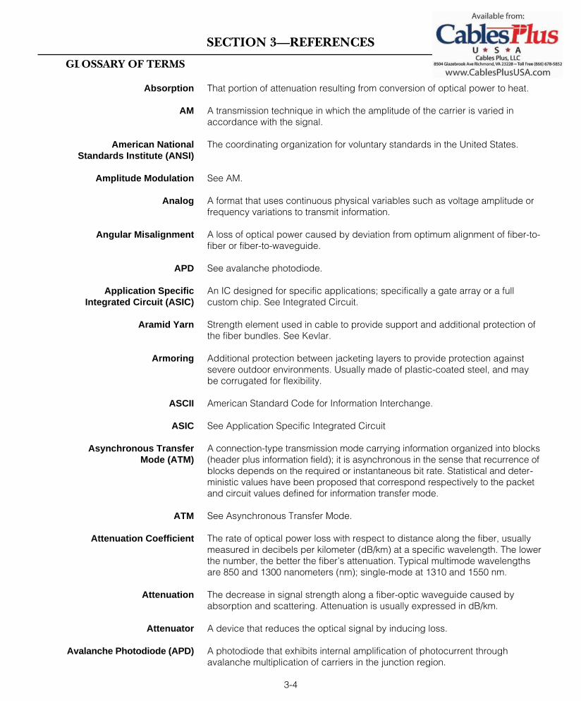
SECTION 3—REFERENCES
That portion of attenuation resulting from conversion of optical power to heat.
A transmission technique in which the amplitude of the carrier is varied inaccordance with the signal.
The coordinating organization for voluntary standards in the United States.
See AM.
A format that uses continuous physical variables such as voltage amplitude orfrequency variations to transmit information.
A loss of optical power caused by deviation from optimum alignment of fiber-to-fiber or fiber-to-waveguide.
See avalanche photodiode.
An IC designed for specific applications; specifically a gate array or a fullcustom chip. See Integrated Circuit.
Strength element used in cable to provide support and additional protection ofthe fiber bundles. See Kevlar.
Additional protection between jacketing layers to provide protection againstsevere outdoor environments. Usually made of plastic-coated steel, and maybe corrugated for flexibility.
American Standard Code for Information Interchange.
See Application Specific Integrated Circuit
A connection-type transmission mode carrying information organized into blocks(header plus information field); it is asynchronous in the sense that recurrence ofblocks depends on the required or instantaneous bit rate. Statistical and deter-ministic values have been proposed that correspond respectively to the packetand circuit values defined for information transfer mode.
See Asynchronous Transfer Mode.
The rate of optical power loss with respect to distance along the fiber, usuallymeasured in decibels per kilometer (dB/km) at a specific wavelength. The lowerthe number, the better the fiber’s attenuation. Typical multimode wavelengthsare 850 and 1300 nanometers (nm); single-mode at 1310 and 1550 nm.
The decrease in signal strength along a fiber-optic waveguide caused byabsorption and scattering. Attenuation is usually expressed in dB/km.
A device that reduces the optical signal by inducing loss.
A photodiode that exhibits internal amplification of photocurrent throughavalanche multiplication of carriers in the junction region.
3-4
Absorption
AM
American NationalStandards Institute (ANSI)
Amplitude Modulation
Analog
Angular Misalignment
APD
Application Specific Integrated Circuit (ASIC)
Aramid Yarn
Armoring
ASCII
ASIC
Asynchronous TransferMode (ATM)
ATM
Attenuation Coefficient
Attenuation
Attenuator
Avalanche Photodiode (APD)
GLOSSARY OF TERMS
india
Cable Plus USA

SECTION 3—REFERENCES
That portion of the premises telecommunication wiring which provides intercon-nections between telecommunications closets, equipment rooms, and networkinterfaces. The backbone wiring consists of the transmission media (fiber opticcable), main and intermediate cross-connects, and terminations for thetelecommunications closets, equipment rooms, and network interfaces. Thebackbone wiring can be further classified as interbuilding backbone (wiringbetween buildings), or intrabuilding backbone (wiring within a building).
The range of frequencies within which a waveguide or terminal device cantransmit data.
A method of communication in which a signal is transmitted at its original fre-quency without being impressed on a carrier.
A unit of signaling speed equal to the number of signal symbols per secondwhich may or may not be equal to the data rate in bits per second.
An optical device, such as a partially reflecting mirror, that splits a beam of light intotwo or more beams and that can be used in fiber optics for directional couplers.
See Microbending or Macrobending. A form of increased attenuation in a fibercaused by bending a fiber around a restrictive curvature (a macrobend) or fromminute distortions in the fiber (microbends).
See Cable Bend Radius.
See Bit-Error Rate.
A modulation code where each bit period begins with a change of level. For a 1,an additional transition occurs in midperiod. For a 0, no additional changeoccurs. Thus, a 1 is at both high and low during the bit period. A 0 is either highor low, but not both, during the entire bit period.
See broadband integrated services digital network.
The fraction of bits transmitted that are received incorrectly.
The smallest unit of information upon which digital communications are built;also, an electrical or optical pulse that carries this information. A binary digit.
A tight-buffer cable design that is used with individual strength members foreach fiber, which allows for direct termination to the cable without usingbreakout kits or splice panels. One can “break out” several fibers at any loca-tion, routing the other fibers elsewhere.
A proposed form of the integrated services digital network (ISDN) which willcarry digital transmission at rates equal to or greater than the T-1 rate (1.544megabits per second). Proposed BISDN standards packetize information(voice, data, video) into fixed-length cells for transmission over synchronousoptical networks.
A method of communication in which the signal is transmitted by beingimpressed on a higher frequency carrier.
3-5
Backbone wiring
Bandwidth
Baseband
Baud
Beamsplitter
Bend or Bending Loss
Bend Radius
BER
Biphase-M Code
BISDN
Bit-Error Rate (BER)
Bit
Breakout Cable
Broadband ISDN (BISDN)
Broadband
india
Cable Plus USA
india
Cable Plus USA - footer

SECTION 3—REFERENCES
A protective layer, such as an acrylic polymer, applied over the fiber claddingfor protective purposes.
A hard plastic tube having an inside diameter several times that of a fiber thatholds one or more fibers.
A protective coating applied directly to the fiber such as a coating, an innerjacket, or a hard tube.
A network topology in which all terminals are attached to a transmissionmedium serving as a bus.
A binary string (usually of 8 bits) operated as a unit.
Fiber-optic cable that has connectors installed on one or both ends. Generaluse of these assemblies includes the interconnection of fiber-optic systemsand opto-electronic equipment. If connectors are attached to only one end ofa cable, it is known as a pigtail. If connectors are attached to both ends, it isknown as a jumper.
This term implies that the cable is experiencing a tensile load. Free bendimplies a smaller allowable bend radius since it is at a condition of no load.
One or more optical fibers enclosed within protective covering(s) and strengthmembers.
See Consultative Committee on International Telegraph and Telephone.
The center component of a cable, it serves as an antibuckling element to resisttemperature-induced stresses. Sometimes serves as a strength element. Thecentral member is composed of steel, fiberglass, or glass-reinforced plastic.
This specification describes how well a coupler can distinguish wavelengths.
A communications path or the signal sent over that channel. Through multi-plexing several channels, voice channels can be transmitted over an opticalchannel.
This condition occurs because different wavelengths of light travel at differentspeeds. No transmitter produces a pure light source of only one wavelength.Instead, sources produce a range of wavelengths around a center wave-length. These wavelengths travel at slightly different speeds, resulting in pulsespreading that increases with distance.
The portion of the NTSC color-television signal that contains the color information.
The lower index-of-refraction material that surrounds the core of an opticalfiber, causing the transmitted light to travel down the core.
Tools which allow the operator to break or scribe the fiber with a 90 degreeendface perpendicular to the axis of the fiber with little surface damage orirregularities to the fiber.
Thermoplastic layer directly adhered to cladding to give flexibility andstrength.
3-6
Buffer Coating
Buffer Tube
Buffer
Bus Network
Byte
Cable Assembly
Cable Bend Radius
Cable
CCIT
Central Member
Channel Separation
Channel
Chromatic Dispersion
Chrominance Signal
Cladding
Cleavers
Coating
india
Cable Plus USA

SECTION 3—REFERENCES
A central conductor surrounded by an insulator, which in turn is surroundedby a tubular outer conductor, which is covered by more insulation.
Coder-decoder. Coder converts analog signals to digital for transmission;decoder converts digital signal to analog at other end.
Lasers emit a parallel beam which is nearly coherent (as opposed to a LEDwhich would be considered incoherent). The degree of coherence is a betterphrasing.
A logic family used in transmitters and receivers. Potentially a replacement forTTL.
Pipe or tubing through which cables can be pulled or housed.
A mechanical or optical device that provides a demountable connectionbetween two fibers or a fiber and a source or detector, connecting transmit-ters, receivers, and cables into working links. Commonly used connectorsinclude Biconic, ST, and SMA.
A component division of the International Telecommunications (ITU) thatattempts to establish international telecommunications standards by issuingrecommendations which express, as closely as possible, an internationalconsensus.
The light-conducting central portion of an optical fiber composed of a mate-rial with a higher index of refraction than the cladding.
An optical device that combines or splits signals from optical fibers.
Each channel should appear only at its intended port and not at any otheroutput port. The crosstalk specification expresses how well a coupler main-tains this port-to-port separation. Crosstalk, for example, measures how muchof the 820 nm wavelength appears at the 1300 nm port. A crosstalk of 20 dBwould mean that 1 percent of the signal appears at the unintended port.
A technique of measuring optical fiber attenuation by measuring the opticalpower at two points at different distances from the test source.
In single-mode fiber, the wavelength below which the fiber ceases to besingle mode.
The thermally induced current that exists in a photodiode in the absence ofincident optical power; the lowest level of thermal noise.
The number of bits of information in a transmission system, expressed in bits persecond (bps) and which may or may not be equal to the signal or baud rate.
See Decibel.
Decibel referenced to a milliwatt.
Decibel referenced to a microwatt.
3-7
Coaxial Cable
Codec
Coherence
Complementary Metal-OxideSemiconductor (CMOS)
Conduit
Connector
Consultative Committee onInternational Telegraph and
Telephone (CCIT)
Core
Coupler
Crosstalk
Cutback Method
Cutoff Wavelength
Dark Current
Data Rate
dB
dBm
dBµ
india
Cable Plus USA

SECTION 3—REFERENCES
A unit of measurement indicating relative power on a logarithmic scale. Oftenexpressed in reference to a fixed value, such as dBm (1 milliwatt) or dBµ (1microwatt).
The receiving photodiode.
The loss of power at a joint that occurs when the transmitting half has a diam-eter greater than the diameter of the receiving half. The loss occurs when cou-pling light from a source to fiber, from fiber to fiber, or from fiber to detector.
An optical filter that transmits light selectively according to wavelength.
Nonmetallic and, therefore, nonconductive. Glass fibers are considered to bedielectric. A dielectric cable contains no metallic components.
The amplitude change, usually of the 3.58-MHz color subcarrier, caused by theoverall circuit as the luminance is varied from blanking to white level. It isexpressed in percent or in decibels.
An array of fine, parallel, equally spaced reflecting or transmitting lines that mutuallyenhance the effects of diffraction to concentrate the diffracted light in a few direc-tions determined by the spacing of the lines and by the wavelength of the light.
An array of fine, parallel reflecting lines caused by the interaction of the waveand an object. Diffraction causes deviation of waves from their paths.
A data format that uses two physical levels to transmit information corre-sponding to 0s and 1s. A discrete or discontinuous signal.
The temporal spreading of a light signal in an optical waveguide, which iscaused by sight signals traveling at different speeds through a fiber either dueto modal or chromatic effects.
A two-fiber cable suitable for duplex transmission.
Transmission in both directions, either one direction at a time (half duplex) orboth directions simultaneously (full duplex).
See Emitter Coupled Logic.
Electronic Industries Association. A standards association that publishes testprocedures.
One that is made from a plastic material (elastic) formed into a mold. The moldallows for a hole to be made and the elastomeric material is flexible enough sothat fibers can be positioned and firm enough so the fibers are retained duringhandling and splicing without the need for repositioning equipment.
Although exhibiting great resistance to electromagnetic pulses (radiation), fiberoptics are not totally immune to the effects of EMP. Special optical fiber can bepurchased for usage in applications where EMP may be a factor.
3-8
Decibel (dB)
Detector
Diameter Mismatch Loss
Dichroic Filter
Dielectric
Differential Gain
Diffraction Grating
Diffraction
Digital
Dispersion
Duplex Cable
Duplex Transmission
ECL
EIA
Elastomeric Splice
Electromagnetic Pulses (EMP)
india
Cable Plus USA
india
Cable Plus USA - footer

SECTION 3—REFERENCES
A device that allows the routing of optical signals (under electronic control),without an intermediary conversion to electronic signals.
Any electrical or electromagnetic interference that causes undesirable response,degradation, or failure in electronic equipment. Optical fibers neither emit norreceive EMI.
An infrared region invisible to the human eye.
See Equilibrium Mode Distribution.
Electromagnetic interference, like RFI, is something that does not affect fiberoptic. See Electromagnetic Interference.
A common digital logic used in fiber-optic transmitters and receivers that isfaster than TTL.
See Electromagnetic Pulses.
The steady modal state of a multimode fiber in which the relative power distribu-tion among modes is independent of fiber length.
Ethernet is a bus network LAN using CSMSA/CD. Originally created by XeroxCorporation, Digital Equipment Corporation, and Intel Corporation, Ethernet wasdesigned to use coaxial cable at data rates up to 10 Mbps.
In a fiber-optic coupler, the optical loss from that portion of light that does notemerge from the nominally operational ports of the device.
In a fiber interconnection, that portion of loss that is not intrinsic to the fiber, butis related to imperfect joining, which may be caused by the connector or splice.
See Fiber Distributed Data Interface.
See frequency division multiplexing.
A mechanical fixture, generally a rigid tube, used to confine and align the pol-ished or cleaved end of a fiber in a connector. Generally associated with fiber-optic connectors.
A standard for a 100 Mbit/sec fiber-optic local area network.
A transmitter, receiver, and cable assembly that can transmit informationbetween two points.
Thin filament of glass. An optical waveguide consisting of a core and a claddingwhich is capable of carrying information in the form of light.
See frequency modulation.
A two-way communication circuit using two paths, arranged so signals are trans-mitted one direction on one path, and in the opposite direction on the other path.
3-9
Electro-Optical Switch
Electromagnetic Interference (EMI)
Electromagnetic Spectrum
EMD
EMI
Emitter Coupled Logic (ECL)
EMP
Equilibrium Mode Distribution(EMD)
Ethernet
Excess Loss
Extrinsic Loss
FDDI
FDM
Ferrule
Fiber Distributed Data Interface(FDDI)
Fiber-Optic Link
Fiber
FM
Four-Wire Circuit

SECTION 3—REFERENCES
A linear set of transmitted bits which define a basic transport element. In syn-chronous transmission, the frames are defined by rigid timing protocolsbetween the transmitting and receiving ends. In asynchronous transmission,frames are defined by bits embedded within the frame, either at the beginningof the frame or at the beginning and end of the frame.
A method of deriving two or more simultaneous continuous channels from atransmission medium connecting two points by assigning separate portions ofthe available frequency spectrum to each of the individual channels beingshifted to and allotted a different frequency band.
A method of transmission in which the carrier frequency varies in accordancewith the signal.
Reflection losses at ends of fibers caused by differences in refractive indexbetween the core glass and the immersion medium due to Fresnel reflections.
The reflection that occurs at the planar junction of two materials having differentrefractive indices; Fresnel reflection is not a function of the angle of incidence.
See Duplex Transmission.
The joining together of glass fibers by melting them together using an electricarc. This is a permanent method considered to be highly reliable and with thelowest loss.
An instrument that permanently bonds two fibers together by heating andfusing them.
Loss resulting from the end separation of two axially aligned fibers.
A unit of frequency that is equal to one billion cycles per second.
Optical fiber in which the refractive index of the core is in the form of a para-bolic curve, decreasing toward the cladding. This process tends to speed upthe modes. Light is gradually refocused by refraction in the core. The center,or axial, mode is the slowest. (See Step Index.)
Noise that results when equipment is grounded at ground points having dif-ferent potentials and thereby created an unintended current path. The dielec-tric of optical fibers provide electrical isolation that eliminated ground loops.
See Duplex Transmission.
See High-Definition Television.
A television format offering resolution and picture quality comparable to 35-mm motion picture film. A television standard under development by CCIR.
An interconnection point for high-speed interoffice trunks. Multiplexed on high-capacity (typically fiber), traffic is routed through the hub to its destination.
A unique type of cable designed for multipurpose applications where bothoptical fiber and twisted pair wires are jacketed together for situations whereboth technologies are presently used.
3-10
Frame
Frequency Division Multiplexing(FDM)
Frequency Modulation
Fresnel Reflection Loss
Fresnel Reflection
Full Duplex
Fusion Splice
Fusion Splicer
Gap Loss
Gigahertz (GHz)
Graded Index
Ground Loop Noise
Half Duplex
HDTV
High-Definition Television (HDTV)
Hub
Hybrid Optical Cable
india
Cable Plus USA

SECTION 3—REFERENCES
See integrated circuit.
Institute of Electrical and Electronics Engineering.
A fluid whose index of refraction equals that of the fiber’s core. Used to reduceFresnel reflections at fiber ends.
The ratio of light velocity in a vacuum compared to its velocity in the transmis-sion medium is known as index of refraction. Light travels in a vacuum throughspace at 186,291 miles per second. Divided by its speed through optical glass(122,372 miles per second), the calculation for its index of refraction is 1.51.
The method for specifying the performance of a connector or splice.
A complete electronic device including transistors, resistors, capacitors, plus allwiring and interconnections fabricated as a unit on a single chip.
A set of international technical standards that permit the transmission of voice,data, facsimile, slow-motion video, and other signals over the same pair of wiresor optical fibers.
See Integrated Services Digital Network.
The outer, protective covering of fiber-optic cable.
Strength element used in cable to provide support and additional protection ofthe fiber bundles Kevlar is the registered trademark of E. I. Dupont de Nemours. See Aramid Yarn.
A unit of tensile force expressed in thousands of pounds per square inch. Usually used as the specification for fiber proof test, i.e., 50 KPSI.
See Local Area Network.
An acronym for Light Amplification by Stimulated Emission of Radiation. A lightsource used primarily in single-mode fiber-optic links. Center wavelengths of1300 nm are most common, although some operate at 1550 nm. Lasers have avery narrow spectral width compared to LEDs and average power of a lasersource is also much higher than that of LEDs. Modulation frequenciesexceeding 1 GHz are possible.
An electro-optic semiconductor device that emits coherent light with a narrowrange of wavelengths, typically centered around 1310 nm or 1550 nm.
Sometimes called the semiconductor diode. A laser in which the lasing occursat the junction of n-type and p-type semiconductor materials.
See Light Emitting Diode.
A semiconductor that emits incoherent light when forward biased. Used pri-marily with multimode optical communications systems. Center wavelengths aretypically 850 nm or 1300 nm and average power levels are <10 dB to <30 dB.
3-11
IC
IEEE
Index Matching Fluid
Index of Refraction
Insertion Loss
Integrated Circuit (IC)
Integrated Services DigitalNetwork (ISDN)
ISDN
Jacket
Kevlar®
KPSI
LAN
Laser
Laser Diode
Laser Diode (Source)
LED
Light-Emitting Diode (LED)
india
Cable Plus USA
india
Cable Plus USA - footer
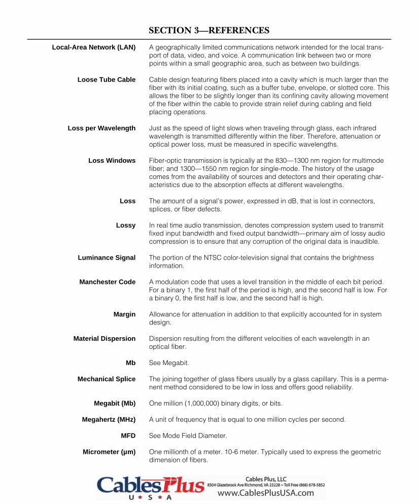
SECTION 3—REFERENCES
A geographically limited communications network intended for the local trans-port of data, video, and voice. A communication link between two or morepoints within a small geographic area, such as between two buildings.
Cable design featuring fibers placed into a cavity which is much larger than thefiber with its initial coating, such as a buffer tube, envelope, or slotted core. Thisallows the fiber to be slightly longer than its confining cavity allowing movementof the fiber within the cable to provide strain relief during cabling and fieldplacing operations.
Just as the speed of light slows when traveling through glass, each infraredwavelength is transmitted differently within the fiber. Therefore, attenuation oroptical power loss, must be measured in specific wavelengths.
Fiber-optic transmission is typically at the 830—1300 nm region for multimodefiber; and 1300—1550 nm region for single-mode. The history of the usagecomes from the availability of sources and detectors and their operating char-acteristics due to the absorption effects at different wavelengths.
The amount of a signal’s power, expressed in dB, that is lost in connectors,splices, or fiber defects.
In real time audio transmission, denotes compression system used to transmitfixed input bandwidth and fixed output bandwidth—primary aim of lossy audiocompression is to ensure that any corruption of the original data is inaudible.
The portion of the NTSC color-television signal that contains the brightnessinformation.
A modulation code that uses a level transition in the middle of each bit period. For a binary 1, the first half of the period is high, and the second half is low. Fora binary 0, the first half is low, and the second half is high.
Allowance for attenuation in addition to that explicitly accounted for in systemdesign.
Dispersion resulting from the different velocities of each wavelength in anoptical fiber.
See Megabit.
The joining together of glass fibers usually by a glass capillary. This is a perma-nent method considered to be low in loss and offers good reliability.
One million (1,000,000) binary digits, or bits.
A unit of frequency that is equal to one million cycles per second.
See Mode Field Diameter.
One millionth of a meter. 10-6 meter. Typically used to express the geometricdimension of fibers.
3-12
Local-Area Network (LAN)
Loose Tube Cable
Loss per Wavelength
Loss Windows
Loss
Lossy
Luminance Signal
Manchester Code
Margin
Material Dispersion
Mb
Mechanical Splice
Megabit (Mb)
Megahertz (MHz)
MFD
Micrometer (µm)
india
Cable Plus USA - footer

SECTION 3—REFERENCES
A modulation code where each 1 is encoded by a level transition in the middleof the bit period. A 0 is represented either by no change in level following a 1 orby a change at the beginning of the bit period following a 0.
Relatively large, rectangular or circular waveguide.
Dispersion resulting from the different transit lengths of different propagatingmodes in a multimode optical fiber.
The transfer of energy between modes. In a fiber, mode coupling occurs untilEMD is reached.
The diameter of the one mode of light propagating in a single-mode fiber. Themode field diameter replaces core diameter as the practical parameter in asingle-mode fiber.
A device that removes higher-order modes to simulate equilibrium modal distribution.
A device that mixes modes to uniform power distribution.
A device that removes cladding modes.
A term used to describe a light path through a fiber, as in multimode or singlemode. A single electromagnetic field pattern within an optical fiber.
Coding of information onto the carrier frequency. This includes amplitude, fre-quency, or phase modulation techniques.
Short for multiplexer-demultiplexer. This device combines or separates lowerlevel digital signals to a higher level signal.
An optical fiber that has a core large enough to propagate more than one mode oflight (typical core/cladding sizes are 50/125, 62.5/125, and 100/140 micrometers).
To put two or more signals into a single data stream.
See numerical aperture.
A unit of measurement equal to one billionth of a meter. 10-9 meters. Typicallyused to express the wavelength of light.
National Electrical Code. Defines building flammatory requirements for indoor cables.
The point of interconnection between the outside service carrier’s telecommunica-tions facilities and the premises wiring and equipment on the end user’s facilities.
A modulation code that is similar to “normal” digital data. The signal is high for a1 and low for a 0. For a string of 1s, the signal remains high and for a string of0s it remains low. Thus, the level changes only when the data level changes.
See Nonreturn to Zero code above.
3-13
Miller Code
Mixing Rod
Modal Dispersion
Mode Coupling
Mode Field Diameter (MFD)
Mode Filter
Mode Scrambler
Mode Stripper
Mode
Modulation
Muldem
Multimode Fiber
Multiplex
NA
Nanometer (nm)
NEC
Network Interface
Nonreturn to Zero (NRZ)
NRZ
india
Cable Plus USA
india
Cable Plus USA - footer

SECTION 3—REFERENCES
A modulation code where 0 is represented by a change in level, and a 1 is rep-resented by no change in level. Thus, the level will go from high to low or fromlow to high for each 0. It will remain at its present level for each 1. An importantthing to notice here is that there is no firm relationship between 1s and 0s ofdata and the highs and lows of the code. A binary 1 can be represented byeither a high or a low, as can a binary 0.
The mathematical measure of the fiber’s ability to accept lightwaves fromvarious angles and transmit them down the core. A large difference between therefractive indices of the core and the cladding means a larger numerical aper-ture (NA). The larger the NA, the more power that can be coupled into the fiber.For short distances this is advantageous; however, for transmitting long dis-tances the dispersion or pulse spreading is too great.
See Optical Loss Test Set.
A device that receives low-level optical signals from an optical fiber, amplifiesthe optical signal, and inserts it into an outbound optical fiber, without con-verting the signal to electrical pulses as an intermediary step.
An optical device used to distribute light signals between multiple input andoutput fibers.
A glass or plastic fiber that has the ability to guide light along its axis.
A source and power meter combined to measure attenuation or loss.
A method of evaluating optical fibers based on detecting backscattered(reflected) light. Used to measure fiber attenuation, evaluate splice and con-nector joints, and locate faults.
The output pattern of the light is important to understand. As light leaves thechip, it spreads out. Only a portion actually couples into the fiber. A smalleroutput pattern allows more light to be coupled into the fiber. A good sourceshould have a small emission diameter and a small NA. The emission diameterdefines how large the area of emitted light is. The NA defines at what angles thelight is spreading out. If either the emitting diameter or the NA of the source islarger than those of the receiving fiber, some of the optical power will be lost.
The optical power emitted at a specified drive current. An LED emits morepower than a laser operating below the threshold. Above the lasing threshold,the laser’s power increases dramatically with increases in drive current. Ingeneral, the output power of a device is in decreasing order: laser, edge-emit-ting LED, surface-emitting LED.
A communications computer defined by the CCITT as the interface betweenasynchronous terminals and a packet switching network.
(1) A mode of data transmission in which messages are broken into smallerincrements called packets, each of which is routed independently to the desti-nation. (2) The process of routing and transferring data by means of addressedpackets, in which a channel is occupied only during the transmission of thepacket; the channel is then available for other packets.
3-14
NRZI (nonreturn-to-zero,inverted) Code
Numerical Aperture (NA)
OLTS
Optical Amplifier or OpticalRepeater
Optical Coupler
Optical Fiber or Optical Waveguide
Optical Loss Test Set (OLTS)
Optical Time DomainReflectometry (OTDR)
Output Pattern
Output Power
Packet Assembler/ Disassembler(PAD)
Packet Switching

SECTION 3—REFERENCES
A group of binary digits, including data and call-control signals, switched as acomposite whole.
See Packet Assembler/Disassembler.
See Phase Alternation Line.
See Pulse Code Modulation.
See Plastic Clad Silica.
Abbreviation used to denote polyvinyl chloride. A type of plastic material usedto make cable jacketing.
The TV color standard used in Europe and Australia.
An optoelectronic transducer such as a pin photodiode or avalanche photodiode.
A semiconductor device that converts light to electrical current.
A quantum of electromagnetic energy. A “particle” of light.
A generic term implying the combining, switching, and routing of optical (pho-tonic) signals without first converting them to electrical signals.
See Cable Assembly.
The simplest photodiode not widely used in fiber optics. The pin and avalanchephotodiodes overcome the limitations of this device.
A photodiode having a large intrinsic layer sandwiched between p-type and n-type layers.
A step-index fiber with glass core and plastic cladding.
The return or air-handling space located between a roof and a dropped ceiling.Plenum cables must meet higher NEC codes concerning smoke and resistanceto flame than are applied to similar PVC or polyethylene cables without the useof metal conduit.
A term used to describe the orientation of the electric and magnetic fieldvectors of a propagating electromagnetic wave. An electromagnetic wavetheory describes in detail the propagation of optical signals (light).
Ensures that losses are low enough in a fiber-optic link to deliver the requiredpower to the receiver.
A glass rod from which optical fiber is drawn.
A technique in which an analog signal, such as a voice, is converted into adigital signal by sampling the signal’s amplitude and expressing the differentamplitudes as a binary number. The sampling rate must be twice the highestfrequency in the signal.
3-15
Packet
PAD
PAL
PCM
PCS
PE
Phase Alternation Line (PAL)
Photodetector
Photodiode
Photon
Photonic Switching
Pigtail
Pn Photodiode
Pin Photodiode
Plastic-Clad Silica (PCS)
Plenum
Polarization
Power Budget
Preform
Pulse Coded Modulation (PCM)
india
Cable Plus USA
india
Cable Plus USA - footer
SECTION 3—REFERENCES
Abbreviation used to denote polyvinyl chloride. A type of plastic materialused to make cable jacketing. Typically used in riser-rated cables.
Abbreviation used to denote polyvinyl fluoride. A type of material used tomake cable jacketing. Typically used in plenum-rated cables.
In a photodiode, the ratio of primary carriers (electron-hole pairs) created toincident photons. A quantum efficiency of 70% means seven out of 10 inci-dent photons create a carrier.
A terminal device that includes a detector and signal processing electronics.It functions as an optical-to-electrical converter.
The abrupt change in direction of a light beam at an interface between twodissimilar media so that the light beam returns into the medium from which itoriginated its reflection, e.g., a mirror.
The bending of a beam of light in transmission between two dissimilar mate-rials or in a graded index fiber where the refractive index is a continuousfunction of position is known as refraction.
A property of optical materials that relates to the speed of light in the material.
A receiver and transmitter set designed to regenerate attenuated signals.
The time required for a photodiode to respond to optical inputs and produceexternal current. Usually expressed as a rise time and a fall time.
In a photodiode, the ratio of the diode’s output current to input optical power.
A digital modulation coding scheme where the signal level remains low for 0s. For a binary 1, the level goes high for one half of a bit period and then returnslow for the remainder. For each 1 of data, the level goes high and returns lowwithin each bit period. For a string of three 1s, for example, the level goeshigh for each 1 and returns to low.
Radio frequency interference, something that fiber is totally resistant to.
Ensures that all components meet the bandwidth/rise-time requirements ofthe link.
Application for indoor cables that pass between floors. It is normally a verticalshaft or space.
See Return-to-Zero Code.
See Sequential Color and Memory (Sequential Couleurs a Memoire).
The color standard used in France and the area formerly identified as theSoviet Union.
The ratio of signal power to noise power.
3-16
PVC
PVDF
Quantum Efficiency
Receiver
Reflection
Refraction
Refractive Index
Repeater
Response Time
Responsivity
Return to Zero (RZ)
RFI
Rise-Time Budget
Riser
RZ Code
SECAM
Sequential Color and Memory(SECAM)
Signal-to-Noise Ratio (SNR)
india
Cable Plus USA
india
Cable Plus USA - footer

SECTION 3—REFERENCES
A term sometimes used for a single-fiber cable, not to be confused with single-mode fiber.
Transmission in one direction only.
Actually a step index fiber, single-mode fiber has the smallest core size (8micrometers is typical) allowing only an axial mode to propagate in the core. Dispersion is very low. This fiber usually requires a laser light source.
See Systems Network Architecture.
A mathematical law that states the relationship between incident and refractedrays of light: The law shows that the angles depend on the refractive indices ofthe two materials.
See Signal-to-Noise Ratio.
See Synchronous Optical Network.
A transmitting LED or laser diode, or an instrument that injects test signals intofibers.
The total power emitted by the transmitter distributed over a range of wave-lengths spread about the center wavelength is the spectral width.
A container used to organize and protect splice trays.
A container used to organize and protect spliced fibers.
A permanent connection of two optical fibers through fusion or mechanicalmeans. An interconnection method for joining the ends of two optical fibers in apermanent or semipermanent fashion.
Optical component in fiber-optic systems which allows for the emulation of abus topology. Also referred to as a star concentrator.
A network in which all terminals are connected through a single point, such as astar coupler.
The light reflects off the core cladding boundary in a step profile. The glass hasa uniform refractive index throughout the core. (See Graded Index and SingleMode.)
The link from the telephone company central office (CO) to the home or busi-ness (customer’s premises).
A standard for optical network elements providing modular building blocks, fixedoverhead, and integrated operations channels, and flexible payload mappings.
The detailed design, including protocols, switching and transmission, that con-stitutes a telecommunications network.
The basic 24-channel 1.544 Mb/s pulse code modulation system used in theUnited States.
3-17
Simplex Cable
Simplex Transmission
Single-Mode Fiber
SNA
Snell’s Law
SNR
SONET
Source
Spectral Width
Splice Closure
Splice Tray
Splice
Star Coupler
Star Network
Step-Index Fiber
Subscriber Loop or Local Loop
Synchronous Optical Network(SONET)
Systems Network Architecture
T-1

SECTION 3—REFERENCES
3-18
TDM
Tee Coupler
Thermal Noise
Throughput Loss
Throughput
Tight Buffer Cable
Time-Division Multiplexing (TDM)
Token Bus
Token Passing
Token Ring
Topology
Transceiver
Transducer
Transistor-Transistor Logic (TTL)
Transmitter
Voice Circuit
See Time Division Multiplexing.
A three-port optical coupler.
Noise resulting from thermally induced random fluctuations in current in thereceiver’s load resistance.
In a fiber-optic coupler, the ratio of power at the throughput port to the power atthe input port.
The total useful information processed or communicated during a specified timeperiod. Expressed in bits per second or packets per second.
Cable design featuring one or two layers of protective coating placed over theinitial fiber coating which may be on an individual fiber basis or in a ribbonstructure.
Digital multiplexing by taking one pulse at a time from separate signals andcombining them in a single, synchronized bit stream.
A network with a bus or tree topology using token passing access control.
A method whereby each device on a local area network receives and passesthe right to use the channel. Tokens are special bit patterns or packets, usuallyseveral bits in length, which circulate from node to node when there is nomessage traffic. Possession of the token gives exclusive access to the networkfor message transmission.
A registered trademark of IBM that represents their token access procedureused on a network with a sequential or ring topology.
Network topology can be centralized or decentralized. Centralized networks, orstar-like networks, have all nodes connected to a single node. Alternativetopology is distributed; that is, each node is connected to every other node.
Typical topology names include bus, ring, star, and tree.
A device that embodies the characteristics of a receiver and a transmitter withinone unit.
A device for converting energy from one form to another, such as optical energyto electrical energy.
A common digital logic circuits used in a fiber-optic transmitter.
An electronic package that converts an electrical signal to an optical signal.
A circuit able to carry one telephone conversation or its equivalent; the standardsubunit in which telecommunication capacity is counted. The digital equivalentis 56 kbit/sec in North America. Common voice networks are:
T1 42 channels 1.544 Mbit/secT3 672 channels 45 Mbit/secT3C 1344 channels 90 Mbit/sec
india
Cable Plus USA
india
Cable Plus USA - footer

SECTION 3—REFERENCES
A graphical representation of a varying quantity. Usually, time is represented onthe horizontal axis, and the current or voltage value is represented on a verticalaxis.
Multiplexing of signals by transmitting them at different wavelengths through thesame fiber. A method of multiplexing two or more optical channels separated bywavelength.
The distance between two crests of an electromagnetic waveform, usually mea-sured in nanometers (nm).
See Wavelength Division Multiplexing.
Wavelength at which net chromatic dispersion of an optical fiber is zero. Ariseswhen waveguide dispersion cancels out material dispersion.
3-19
Waveform
Wavelength-Division Multiplexing(WDM)
Wavelength
WDM
Zero Dispersion Wavelength
india
Cable Plus USA
india
Cable Plus USA - footer

india
Cable Plus USA
india
Cable Plus USA - footer


