
Leakage problems in dams built on evaporites. The case of La …€¦ · ar, Germany, have suffered...
16
Leakage problems in dams built on evaporites. The case of La Loteta Dam (NE Spain), a reservoir in a large karstic depression generated by interstratal salt dissolution Francisco Gutiérrez a, ⁎, Morteza Mozafari b , Domingo Carbonel a , René Gómez c , Ezzatollah Raeisi b a Departamento de Ciencias de la Tierra, Universidad de Zaragoza, C/. Pedro Cerbuna 12, 50009 Zaragoza, Spain b Department of Earth Sciences, Shiraz University, Iran c Confederación Hidrográfica del Ebro, Paseo Sagasta 24-28, Zaragoza, Spain abstract article info Article history: Received 6 May 2014 Received in revised form 24 October 2014 Accepted 9 December 2014 Available online 19 December 2014 Keywords: Evaporite karst Subsidence Reservoir Seepage Grout curtain La Loteta Reservoir, with a storage capacity of 105 hm 3 , is located in a large karst depression around 6 km long on the southern margin of the Ebro River valley, NE Spain. Geomorphological mapping and borehole data indicate that the development of the basin is related to subsidence due to interstratal dissolution of the underlying halite- and glauberite-bearing evaporites. The dam site corresponds to the water gap carved by the small drainage that captured the formerly internally drained depression. Here, the foundation and abutments of the dam include a horizontal and laterally extensive gypsum unit 11 m thick. This sedimentary package showed considerable evidence of karstification in the excavation carried out during the construction of the dam, especial- ly in the left abutment, where it was largely removed. The watertightness system of the ca. 1.5 km long earth dam includes a vertical clay core, a horizontal clay blanket, a cut-off wall, and grout curtains 675 m and 255 m long on the left and right abutments, respectively. Multiple data including leakage discharge measured in the different zones of the drainage system, seepage points mapped downstream of the dam, borehole and piezometric data, and an equipotential map, reveal that leakage essentially occurs through the gypsum unit. The main leakage occurs beneath and next to the left edge of the dam body. This water loss and the associated enlargement of karst conduits are also supported by settlement measured on the dam crest and the occurrence of sinkholes within the reservoir, next to the left abutment. Additional seepage across the grout curtain in both abutments is also identified. Although unlikely, there is also the potential for the water to escape towards an adjacent wa- tershed, where the base level is located below the maximum water level of the reservoir. An additional cut-off wall has been projected to block the main leakage path. © 2014 Elsevier B.V. All rights reserved. 1. Introduction The number of accessible papers and reports documenting problems related to evaporite karst in dams and reservoirs is rather limited (Calcano and Alzurra, 1967; James, 1992; Pearson, 1999; Johnson, 2008; Milanovic, 2011; Cooper and Gutiérrez, 2013), especially if compared with the extensive literature dealing with the impacts of carbonate karst on dams (e.g., Romanov et al., 2003; Milanovic, 2004). This circumstance, despite the extensive areas covered by evaporite rocks at or near the surface worldwide (Warren, 2006), may be attributed to several factors: (1) evaporites, due to their high solubility, tend to be avoided in dam site selection; (2) carbonate rocks, with higher mechan- ical strength and lower erodibility than evaporites (mainly gypsum), commonly form more suitable water gaps for dam construction from the topographic and mechanical standpoints (i.e., narrow canyons flanked by resistant abutments); and (3) most probably, a significant proportion of case histories from numerous countries have not been documented or remain confidential (James, 1992; Pearson, 1999). The presence of gypsum in dam sites and/or reservoirs may pose sig- nificant problems that may (1) require costly and prolonged remedial measures; (2) reduce or annul the efficiency of the hydraulic structure; and (3) eventually lead to catastrophic failures (James, 1992; Johnson, 2008). The impounding of a reservoir entails imposing unprecedented and unnatural high hydraulic gradients. The stored water may escape through pre-existing karst cavities located beneath the dam and/or at the abutments. Some dams have failed to ever retain any significant amount of water due to excessive leakage related to the presence of well-developed gypsum karst; e.g., Hondo Reservoir, New Mexico (James, 1992; Pearson, 1999), Cedar Canyon Dam, South Dakota (Rahn and Davies, 1996), and Anchor Dam, Wyoming (Jarvis, 2003). Anchor Dam was built despite more than 50 sinkholes and stream losses Engineering Geology 185 (2015) 139–154 ⁎ Corresponding author. Tel.: +34 976 761090. E-mail addresses: [email protected] (F. Gutiérrez), [email protected] (M. Mozafari), [email protected] (D. Carbonel), [email protected] (R. Gómez), [email protected] (E. Raeisi). http://dx.doi.org/10.1016/j.enggeo.2014.12.009 0013-7952/© 2014 Elsevier B.V. All rights reserved. Contents lists available at ScienceDirect Engineering Geology journal homepage: www.elsevier.com/locate/enggeo
Transcript of Leakage problems in dams built on evaporites. The case of La …€¦ · ar, Germany, have suffered...

Engineering Geology 185 (2015) 139–154
Contents lists available at ScienceDirect
Engineering Geology
j ourna l homepage: www.e lsev ie r .com/ locate /enggeo
Leakage problems in dams built on evaporites. The case of La Loteta Dam(NE Spain), a reservoir in a large karstic depression generated byinterstratal salt dissolution
Francisco Gutiérrez a,⁎, Morteza Mozafari b, Domingo Carbonel a, René Gómez c, Ezzatollah Raeisi b
a Departamento de Ciencias de la Tierra, Universidad de Zaragoza, C/. Pedro Cerbuna 12, 50009 Zaragoza, Spainb Department of Earth Sciences, Shiraz University, Iranc Confederación Hidrográfica del Ebro, Paseo Sagasta 24-28, Zaragoza, Spain
⁎ Corresponding author. Tel.: +34 976 761090.E-mail addresses: [email protected] (F. Gutiérrez), mo
(M. Mozafari), [email protected] (D. Carbonel), [email protected] (E. Raeisi).
http://dx.doi.org/10.1016/j.enggeo.2014.12.0090013-7952/© 2014 Elsevier B.V. All rights reserved.
a b s t r a c t
a r t i c l e i n f oArticle history:Received 6 May 2014Received in revised form 24 October 2014Accepted 9 December 2014Available online 19 December 2014
Keywords:Evaporite karstSubsidenceReservoirSeepageGrout curtain
La Loteta Reservoir, with a storage capacity of 105 hm3, is located in a large karst depression around 6 km long onthe southern margin of the Ebro River valley, NE Spain. Geomorphological mapping and borehole data indicatethat the development of the basin is related to subsidence due to interstratal dissolution of the underlyinghalite- and glauberite-bearing evaporites. The dam site corresponds to the water gap carved by the smalldrainage that captured the formerly internally drained depression. Here, the foundation and abutments of thedam include a horizontal and laterally extensive gypsum unit 11 m thick. This sedimentary package showedconsiderable evidence of karstification in the excavation carried out during the construction of the dam, especial-ly in the left abutment, where itwas largely removed. Thewatertightness systemof the ca. 1.5 km long earth damincludes a vertical clay core, a horizontal clay blanket, a cut-off wall, and grout curtains 675m and 255m long onthe left and right abutments, respectively. Multiple data including leakage discharge measured in the differentzones of the drainage system, seepage points mapped downstream of the dam, borehole and piezometric data,and an equipotential map, reveal that leakage essentially occurs through the gypsum unit. The main leakageoccurs beneath and next to the left edge of the dam body. This water loss and the associated enlargement ofkarst conduits are also supported by settlement measured on the dam crest and the occurrence of sinkholeswithin the reservoir, next to the left abutment. Additional seepage across the grout curtain in both abutmentsis also identified. Although unlikely, there is also the potential for the water to escape towards an adjacent wa-tershed, where the base level is located below the maximum water level of the reservoir. An additional cut-offwall has been projected to block the main leakage path.
© 2014 Elsevier B.V. All rights reserved.
1. Introduction
The number of accessible papers and reports documenting problemsrelated to evaporite karst in dams and reservoirs is rather limited(Calcano and Alzurra, 1967; James, 1992; Pearson, 1999; Johnson,2008; Milanovic, 2011; Cooper and Gutiérrez, 2013), especially ifcompared with the extensive literature dealing with the impacts ofcarbonate karst on dams (e.g., Romanov et al., 2003; Milanovic, 2004).This circumstance, despite the extensive areas covered by evaporiterocks at or near the surfaceworldwide (Warren, 2006),may be attributedto several factors: (1) evaporites, due to their high solubility, tend to beavoided in dam site selection; (2) carbonate rocks,with highermechan-ical strength and lower erodibility than evaporites (mainly gypsum),
[email protected]@chebro.es (R. Gómez),
commonly form more suitable water gaps for dam construction fromthe topographic and mechanical standpoints (i.e., narrow canyonsflanked by resistant abutments); and (3) most probably, a significantproportion of case histories from numerous countries have not beendocumented or remain confidential (James, 1992; Pearson, 1999).
The presence of gypsum in damsites and/or reservoirsmay pose sig-nificant problems that may (1) require costly and prolonged remedialmeasures; (2) reduce or annul the efficiency of the hydraulic structure;and (3) eventually lead to catastrophic failures (James, 1992; Johnson,2008). The impounding of a reservoir entails imposing unprecedentedand unnatural high hydraulic gradients. The stored water may escapethrough pre-existing karst cavities located beneath the dam and/or atthe abutments. Some dams have failed to ever retain any significantamount of water due to excessive leakage related to the presence ofwell-developed gypsum karst; e.g., Hondo Reservoir, New Mexico(James, 1992; Pearson, 1999), Cedar Canyon Dam, South Dakota (Rahnand Davies, 1996), and Anchor Dam, Wyoming (Jarvis, 2003). AnchorDam was built despite more than 50 sinkholes and stream losses
140 F. Gutiérrez et al. / Engineering Geology 185 (2015) 139–154
associated with karstified Triassic gypsum had been reported in the res-ervoir area. During the first attempt to fill the reservoir, numerous addi-tional sinkholeswere reported. A collapse around 100macross and 20mdeep occurred upstream of the concrete dam and was isolated by theconstruction of an additional dike that limited the operational waterlevel of the reservoir and reduced by 50% its storage capacity. After30 years of costly attempts to repair the reservoir, it has never heldmore than a small pond (Jarvis, 2003).
The water escaping from the reservoir may rapidly increase thepermeability of the dam foundation and abutments through two mainprocesses: (1) washing out of sediments filling dissolutional features,frequently referred to as internal erosion or piping; and (2) dissolvinggypsumwith the consequent enlargement of pre-existing karst channelsor the creation of new leakage pathways. Karstification proceeds at amuch higher rate in gypsum than in carbonate rocks due to the highersolubility and much rapid dissolution kinetics of the former (GutiérrezandCooper, 2013). The equilibriumsolubilities of gypsum(CaSO4·2H2O)and halite (NaCl) are 2.4 g/l and 360 g/l, respectively. By comparison, thesolubilities of calcite (CaCO3) and dolomite (MgCa[CO3]2) are generallylower than 0.1 g/l in normal meteoric water (Dreybrodt, 2004; Fordand Williams, 2007). Moreover, the dissolution kinetics of gypsum ischaracterised by a mixed transport- and surface-reaction-controlledbehaviour; i.e., dissolution rate largely depends on the hydrodynamiccondition of the solvent. Experimental studies indicate a linear relation-ship between gypsum dissolution rate and flow velocity under a laminarflow regime. Under these conditions, the speed at which discontinuityplanes widen by dissolution in limestone and gypsum does not differmuch. However, when the fissures or conduits reach the critical size atwhich the flow turns into turbulent (breakthrough conditions), dissolu-tion rate increases abruptly and exponentially (Raines and Dewers,1997; Jeschke et al., 2001). The dissolutional enlargement of flow pathsis a self-accelerating process, whereby larger openings lead progressivelyto higher discharge and consequently more rapid dissolution (James,1992). The rapidity at which leakage water from reservoirs may enlargekarst pathways by dissolution in gypsum formations is illustrated bymathematical models developed by Romanov et al. (2003), consideringa hydraulic head of 150 m, a grout curtain 97 m deep beneath the damaxis, and fractures with an average width of 0.2 mm. According to thesemodels, water leakage through the enlarging fractures increases steadilyuntil a breakthrough situation with turbulent flow is reached within thelifetime of the structure. At this stage, dissolutional widening increasesabruptly in specific fractures reaching rates as high as 10 cm/yr, withthe consequent exponential increase in the amount of water losses.
In dam foundations where gypsum occurs as a secondary mineralcomponent like veins or detrital particles, dissolution may also createsignificant leakage pathways in a short period of time (James, 1992).In Caspe Dam, NE Spain, founded on argillaceous rocks traversed byabundant gypsum-filled joints, seepage rates increased exponentially(around 4 times in 20–30 days), until they were minimized by groutingto negligible values. According to mass balance calculations, leakagewater was removing around 1000–1500 kg of dissolved gypsum perday from the dam foundation (Araoz, 1992; Mancebo-Piqueras et al.,2012). In Gheisaragh Dam, NW Iran, where the foundation includesclaystones and marls with gypsum veins, increasing water leakage wasrecorded soon after the first impounding in 2005, reducing the reservoirwater level. The composition of the seepage water, with concentrationsin calcium and sulphate 6–12 times higher than in the reservoir, indicatesthat the dam foundation was affected by significant subsurface chemicaland possibly mechanical erosion. A cut-off wall beneath the heel of thedam was proposed as the main measure to remediate the problem(Moradi and Abbasnejad, 2011). Kiyani et al. (2008) assessed the impactof dissolution of gypsum veins in the argillaceous rocks that occur in thefoundation of the Upper Gotvand Dam, Iran. This is a 178 m high earthdam on the Karun River in the Zagros Mountains. The results of 2D and3D seepagemodels utilising afinite elementmethod suggest a permeabil-ity increase of the order of 75–300 times due to complete dissolution of
the gypsum veins that would increase by 240–360 times the leakagerate. The presented examples and modelling results clearly indicate thatthe success in remediating problems related to gypsum dissolution indamsites, a process characterisedby a very rapid kinetics, largely dependson the promptness at which corrective measures are applied.
Active dissolution and internal erosion by leakage water in thefoundation of a dam may cause, in addition to permeability increase, arapid degradation in the mechanical properties of the material bearingthedambody and associated structures. The consequent local or generalloss of basal support may lead to settlements (e.g., Murray andBrowning, 1984) and even the occurrence of sinkholes, compromisingthe serviceability and integrity of the dam. Pearson (1999) presenteda compilation of 34 case histories of dams impacted by problems relatedto gypsum karst. The inventory includes 12 cases (35%) of catastrophicfailures. Obviously, most of them correspond to old structures withdesigns and monitoring systems that would not meet the currentstandards. The failure of St. Francis Dam, California, resulted in a floodthat killed around 600 people in 1928. The collapse of the dam hasbeen attributed to a drastic reduction in the mechanical strength ofthe conglomerates at the right abutment due to dissolution of gypsumveins acting as cement. Seepage water with high calcium and sulphateconcentration emanating from the conglomerates was detected sincethe beginning of the impoundment (Ransome, 1928; James, 1992).TheQuail CreekDike, Utah, failed in 1989, five years after its completion.Significant leakage had been recorded along the downstream toe andleft abutment. The bedrock exposed in the breach zone revealed thinlybedded gypsiferous bedswith solutionally-enlarged joints and conduits.The new dike, a concrete gravity damwith a cut-off trench 23mdeep, isalso affected by leakage and more than 200 sinkholes have been docu-mented within a band 120 m wide upstream of the dam. The remedialmeasures applied include a foundation grouting programme and the in-stallation of a clay blanket upstream of the dam (Payton and Hansen,2003). Theweir, locks, and powerhouse at Hessigheim on the River Neck-ar, Germany, have suffered from severe subsidence related to cavernousTriassic gypsum-rich bedrock. The power plant settled 16 cm during con-struction and 20 cm subsidence was recorded in the lock chambers. Agrout curtain was successfully constructed at the upstream side of thestructures (Wittke and Hermening, 1997). Mosul Dam is a 113 m highand 3.4 km long earth dam on the Tigris River, Iraq. It was completed in1984 and is one of the most important projects of the country. Thereservoir has a storage capacity of 11.1 billion m3 and is located 50 kmupstreamofMosul city,with a populationof 3millionpeople. The founda-tion corresponds to the Miocene Fat'ha Formation, including 6–8 m thickgypsum/anhydrite units interbeddedwith other lithologies. Since the ini-tial filling and despite the permanent grouting programme, reservoirwater flowing through the foundation at depths as high as 100 m iscausing major gypsum dissolution (42–80 tons per day) and significantsettlement in the dam, compromising the safety of the structure and cre-ating social alarm (Guzina et al., 1991; Sissakian et al., 2014). It has beenestimated that the peak of the potential flood generated by a catastrophicfailure of the damwould arrive inMosul in about 9 hwith a stage of 20mand affecting an area occupied by 2 million people. Badush Dam is beingconstructed upstream Mosul city to act as a backstop structure in theevent of a dam burst (Guzina et al., 1991; Sissakian et al., 2014).
A common problem in reservoirs underlain by evaporites is thedevelopment of human-induced sinkholes. Sinkholes that form withinthe reservoir area, especially in the vicinity of the dam, may act aseffective outlet points for leakage water. Several factors may favoursubsidence phenomena (Gutiérrez et al., 2014): (1) overloading imposedby the stored water; (2) rapid and increasing ground water flows underhigh hydraulic gradients with the consequent enlargement of voids byinternal erosion and dissolution; (3) cyclic flooding and drainage ofkarst conduits at the margin of the reservoir related to the oscillatingreservoir water level. The decline of the reservoir level and groundwatertablemay cause buoyancy loss in cavity roofs; and (4) thawing of groundice in permafrost areas. As explained above, the inability to hold water in
141F. Gutiérrez et al. / Engineering Geology 185 (2015) 139–154
Anchor Dam, Wyoming, was mainly related to the occurrence of largesinkholes upstream of the dam (Jarvis, 2003). In the 1980's HorsetoothReservoir, Colorado, underlain by a Permian/Triassic gypsiferous forma-tion, was affected by sinkholes associated with collapse chimneys up to100 m deep. In 2000, a sinkhole was discovered at the upstream toe ofthe dam,whichwas affected by increased seepage andhigh artesian pres-sure (Pearson, 1999; Johnson, 2008). Huoshipo Dam, China, was builtupon karstified gypsum without any previous geological site investiga-tion. The reservoir has been affected by significant leakage of waterflowing through sinkholes formed around 100 m upstream of the dam(Yarou and Cooper, 1997). In Kama Reservoir, pre-Ural region, Russia,the hydrogeological changes related to the project have reactivateda gypsum karst inducing numerous collapse sinkholes with severeland-use implications (Klimchouk and Andrejchuk, 1996). The BratskReservoir, Siberia, has caused the partial thawing of the permafrost andthe development of numerous collapse sinkholes along some coastal sec-tors. During reservoir impounding (1963–1966), sinkhole occurrencereached a spatial-temporal frequency of 200 sinkholes/km2/year, causingsevere damage to buildings and structures outside the reservoir area(Eraso et al., 1995; Trzcinski, 1996; Trzhtsinsky, 2002). The Mont CenisReservoir (Moncenisio Reservoir) is located in a glacial overdeepenedbasin in the Alps, at the French–Italian border, and the left abutment ofthe dam is underlain by Triassic evaporites. In addition to leakage prob-lems, the reservoir has induced numerous sinkholes and geodetic surveysreveal rapid subsidence (6 cm between 1986 and 1988) in an area cover-ing around 6 ha on the margin of the reservoir (Deletie et al., 1990).
Although infrequent, an additional potential problem that might beencountered under adequate topographic and geological conditions istheflowof reservoirwater through underground karst channels towardsan adjacentwatershed. A number of cases have been documented in car-bonate karst areas in which groundwater flows escaping from reservoirstraverse topographic divides and discharge at springs in other surfacecatchments (e.g., Milanovic, 2004). Johnson (2003a) indicates that thepresence of cavernous gypsum units associated with a fault zone in theuppermost sector of the proposed Lower Mangum Reservoir, Oklahoma,could cause the loss of water into an adjacent watershed. This factormight reduce the storage capacity of the projected reservoir by around55%.
Several strategies may be considered from the dam site selectionstage to prevent or reduce problems related to evaporite karst. Apreventive alternative is to avoid valley reaches with evaporites at ornear the surface, especially in dam sites. The proposed site for theUpper Mangum Dam, Oklahoma, was abandoned due to the presenceof cavernous Permian gypsumbeds in the dam foundation and reservoirarea (Johnson, 2003b). A new site was selected 11 km downstream, theLower Mangum Dam site, considered as an adequate location from thegypsum karst standpoint. Here, the karstified gypsum formation foundin Upper Mangum, which dips upstream, is located above the normalmaximum water level in most of the reservoir and the bedrock mainlycorresponds to impervious shales (Johnson, 2003a). In the site proposedfor the Cedar Ridge Dam, Texas, boreholes revealed the presence ofunexpected gypsum beds in the valley sides and beneath the valleyfloor with an aggregate thickness of 10–15 m. In order to avoid theseproblematic rocks, gently dipping upstream, a new dam site wasproposed 8 km upstream, where the top-most gypsum bed is situated23 m beneath the valley bottom (Johnson and Wilkerson, 2013).In some cases in which the evaporites have a limited extent, a feasiblealternative may be their removal by excavation from the dam site.A good example is the Casa de Piedra Dam in Argentina. Here, anunexpected gypsum bed more than 5 m thick with cavities andpaleosinkholes was encountered on the left abutment. The gypsumlayer was removed excavating a deep trench after lowering the watertable 15 m (Marriotti et al., 1990). In case the evaporites cannot beavoided, the dam should incorporate elements aimed at preventingwater leakage through the foundation and abutments of the dam suchas cut-off walls, grout curtains or clay blankets. Milanovic (2004)
presents a comprehensive review of the different measures thatmay be applied to prevent and/or remediate water leakage in damsassociated with karst. The analysed case histories suggest that inmost cases dams built on gypsum-bearing foundations require theapplication of successive post-construction grouting programmes.Probably the most dramatic example is Mosul Dam, Iraq, subject to apermanent grouting programme aimed at filling the voids that continu-ously form by gypsum dissolution in the dam foundation. Around84,000 tons of solid material was injected between 1986 and 2004(Sissakian et al., 2014).
A number of dams in Spain have been affected by problems causedor partially related to gypsum dissolution, such as leakage: EstremeraDam (Jiménez, 1949; Llamas, 1965), Alloz Dam (Fernández et al.,2001), Caspe Dam (Araoz, 1992;Mancebo-Piqueras et al., 2012); or fail-ure: San Juan Reservoir (Gutiérrez et al., 2003). In this work we analyseleakage problems in La Loteta Dam, a very peculiar reservoir built in alarge karst depression developed on subhorizontally-lying Tertiaryevaporites in NE Spain. The main objectives of the paper include:(1) unravelling the origin of the karst depression integrating geomor-phological mapping and the available borehole data; (2) characterisingthe dam site from the karst perspective mainly using data gatheredduring the construction of the structure; (3) analysing the spatial distri-bution of the leakage paths as well as their temporal evolution usingmonitoring data systematically collected by the Ebro Basin WaterAuthority; and (4) documenting subsidence evidence recorded alongthe main leakage path in one of the abutments.
2. The project of La Loteta Reservoir
La Loteta Reservoir is located on the southern margin of the EbroRiver valley, NE Spain, around 40 km upstream Zaragoza City (Figure1). Here, the valley has been carved in a thick Tertiary continentalsuccession consisting of subhorizontally-lying halite- and glauberite-bearing evaporites and argillaceous units. These sediments of the EbroCenozoic basin fill are extensively covered by gravelly terraces andpediments on the southern margin of the valley. The basin of La LotetaReservoir has a peculiar origin. It does not correspond to a dammedvalley section, but to a NW–SE trending dissolution-induced subsidencedepression around 6 km long captured on its NE side by a small ephem-eral stream; the Arroyo del Carrizal (Figure 1). This semi-enclosed flat-floored basin, surrounded by steep slopes along its whole perimeter,except at the water gap carved by the Arroyo del Carrizal, was consid-ered an excellent topographic setting for the construction of a reservoir.It allows the impoundment of a large volume ofwater (104.85 hm3) at astrategic location with the construction of a relative low dam (29 mabove the valley floor) (Lafuente, 2004; Lafuente et al., 2006). Due toits unparallel geomorphic nature, the reservoir has a limited contribut-ing area (25 km2) compared with the maximum impoundment surfacearea (11 km2). Consequently, it has to be filled with water from outsideits catchment. The inflow produced by a flood with a return period of1000 yr would contribute with a volume of water lower than 1.5% ofthe maximum capacity of the reservoir, involving an elevation in thereservoir water level (RWL) of ca. 0.4 m (Lafuente, 2004).
La Loteta project was conceived with twomain aims: (1) Regulatingthe Imperial Canal in its middle reach. This is a remarkable hydraulicstructure 110km long constructed in the secondhalf of the 18th centuryalong the southern margin of the Ebro Valley for irrigation and naviga-tion purposes (Sástago, 1796). The reservoir may store water pumpedfrom the Imperial Canal andmay also supply water to the canal througha ca. 3 km double-pipe conduit system. (2) Quality water supply toZaragoza City and its environs. The reservoir may receive water withlow-ionic content from the Yesa Reservoir in the Pyrenees, via the LaSora Ditch. The execution of the project, with a cost of 72 million euro,lasted from November 1998 to the beginning of 2009. The impound-ment of the reservoir started in February 2009.

Fig. 1. Location of La Loteta Reservoir on the southern margin of the Ebro Valley, upstream Zaragoza City, NE Spain. The shaded relief model shows the ca. 6 km long subsidencebasin generated by interstratal dissolution of salt-bearing evaporites used for the construction of the reservoir. The dam is located at the water gap where the Arroyo del Carrizalcaptured the karstic depression. The flat surface in the reservoir corresponds to impounded water. Note the enclosed Valcardera Depression to the NW of La Loteta Reservoir.Also note the proximity of the reservoir to the El Bayo stream, lying at a lower elevation than the maximum water level of the reservoir. UTM coordinates correspond to thegeodetic system ETRS89.
Fig. 2. Longitudinal section of the dam and distribution of stratigraphic units. The section shows the distribution of dissolution and subsidence features encountered during the excavationof the foundation in both abutments, and the approximate location of the high resistivity anomalies identified at the right abutment. The different features are projected on the axial planeof the dam. The sector on the left edge of the dam crest affected by anomalously high settlement is indicated.
142 F. Gutiérrez et al. / Engineering Geology 185 (2015) 139–154
143F. Gutiérrez et al. / Engineering Geology 185 (2015) 139–154
3. Characteristics of the dam and grout curtain
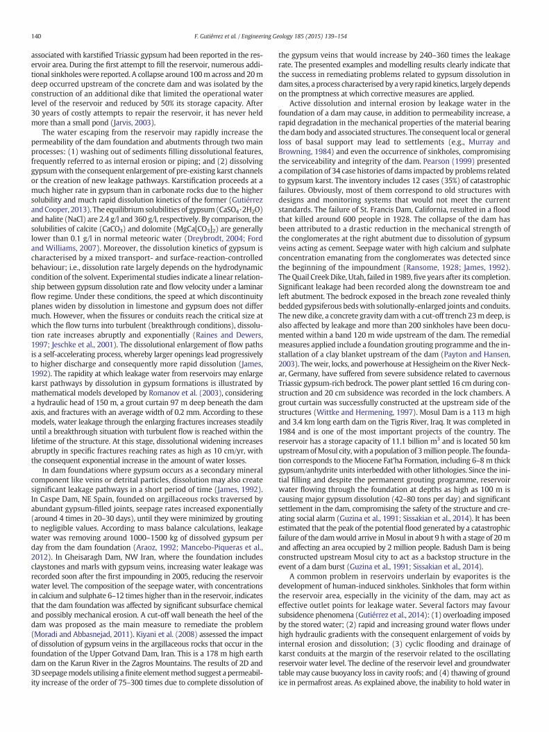
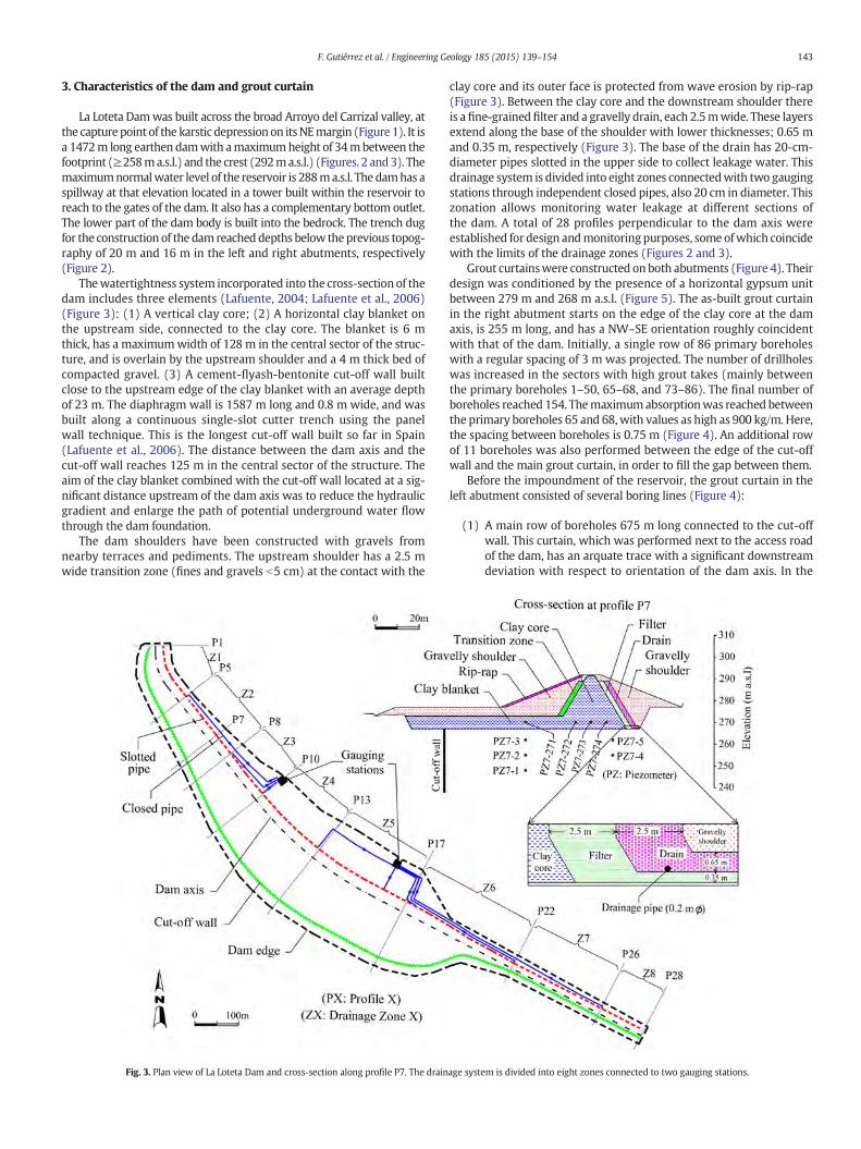
La Loteta Damwas built across the broad Arroyo del Carrizal valley, atthe capturepoint of the karstic depressionon itsNEmargin (Figure 1). It isa 1472m long earthen damwith amaximumheight of 34mbetween thefootprint (≥258ma.s.l.) and the crest (292ma.s.l.) (Figures. 2 and3). Themaximumnormalwater level of the reservoir is 288ma.s.l. The damhas aspillway at that elevation located in a tower built within the reservoir toreach to the gates of the dam. It also has a complementary bottom outlet.The lower part of the dam body is built into the bedrock. The trench dugfor the construction of the damreached depths below theprevious topog-raphy of 20 m and 16 m in the left and right abutments, respectively(Figure 2).
Thewatertightness system incorporated into the cross-section of thedam includes three elements (Lafuente, 2004; Lafuente et al., 2006)(Figure 3): (1) A vertical clay core; (2) A horizontal clay blanket onthe upstream side, connected to the clay core. The blanket is 6 mthick, has a maximumwidth of 128 m in the central sector of the struc-ture, and is overlain by the upstream shoulder and a 4 m thick bed ofcompacted gravel. (3) A cement-flyash-bentonite cut-off wall builtclose to the upstream edge of the clay blanket with an average depthof 23 m. The diaphragm wall is 1587 m long and 0.8 m wide, and wasbuilt along a continuous single-slot cutter trench using the panelwall technique. This is the longest cut-off wall built so far in Spain(Lafuente et al., 2006). The distance between the dam axis and thecut-off wall reaches 125 m in the central sector of the structure. Theaim of the clay blanket combined with the cut-off wall located at a sig-nificant distance upstream of the dam axis was to reduce the hydraulicgradient and enlarge the path of potential underground water flowthrough the dam foundation.
The dam shoulders have been constructed with gravels fromnearby terraces and pediments. The upstream shoulder has a 2.5 mwide transition zone (fines and gravels b5 cm) at the contact with the
Fig. 3. Plan view of La Loteta Dam and cross-section along profile P7. The drain
clay core and its outer face is protected from wave erosion by rip-rap(Figure 3). Between the clay core and the downstream shoulder thereis a fine-grainedfilter and a gravelly drain, each 2.5mwide. These layersextend along the base of the shoulder with lower thicknesses; 0.65 mand 0.35 m, respectively (Figure 3). The base of the drain has 20-cm-diameter pipes slotted in the upper side to collect leakage water. Thisdrainage system is divided into eight zones connectedwith two gaugingstations through independent closed pipes, also 20 cm in diameter. Thiszonation allows monitoring water leakage at different sections ofthe dam. A total of 28 profiles perpendicular to the dam axis wereestablished for design andmonitoringpurposes, some ofwhich coincidewith the limits of the drainage zones (Figures 2 and 3).
Grout curtainswere constructed on both abutments (Figure 4). Theirdesign was conditioned by the presence of a horizontal gypsum unitbetween 279 m and 268 m a.s.l. (Figure 5). The as-built grout curtainin the right abutment starts on the edge of the clay core at the damaxis, is 255 m long, and has a NW–SE orientation roughly coincidentwith that of the dam. Initially, a single row of 86 primary boreholeswith a regular spacing of 3 m was projected. The number of drillholeswas increased in the sectors with high grout takes (mainly betweenthe primary boreholes 1–50, 65–68, and 73–86). The final number ofboreholes reached 154. Themaximumabsorptionwas reached betweenthe primary boreholes 65 and 68,with values as high as 900 kg/m. Here,the spacing between boreholes is 0.75 m (Figure 4). An additional rowof 11 boreholes was also performed between the edge of the cut-offwall and the main grout curtain, in order to fill the gap between them.
Before the impoundment of the reservoir, the grout curtain in theleft abutment consisted of several boring lines (Figure 4):
(1) A main row of boreholes 675 m long connected to the cut-offwall. This curtain, which was performed next to the access roadof the dam, has an arquate trace with a significant downstreamdeviation with respect to orientation of the dam axis. In the
age system is divided into eight zones connected to two gauging stations.

144 F. Gutiérrez et al. / Engineering Geology 185 (2015) 139–154
25m long stretch located next to the edge of the cut-off wall, 35boreholes were drilled with a spacing of around 0.7 m (row I inFigure 4). In the remaining stretch, the curtain comprises 215boreholes with a spacing of 3 m. High grout take was recordedin a section between 435m and 459 m (distance from the originof the curtain), with absorption values as high as 1496 kg/m(Figure 4).
(2) Three secondary rows 12–25m longwithin a band 3mwide justdownstream of the main borehole line and associated with theedge of the dam (rows designated as II in Figure 4). Boreholespacing in these rows vary between 1.3 and 1.5 m. In the twonorthernmost rows, the highest consumption was reached inthe section between 3 m and 14.5 m (distance from the originof the curtain), with grout takes as high as 1590 kg/m. Thiscavernous zone is partially located beneath the dam body andits location seems to coincide with the base of the gypsum unit.
(3) A 33 m long borehole line with orthogonal geometry thatconnects the main boring line with the dam axis beyond theedge of the clay blanket (line III in Figure 4). This line includes30 boreholes with a regular spacing of 1.5 m and the sectionperpendicular to themain curtain includes two rows 1.5m apart.
With the aforementioned layout, a difficult to perceive gap has beendetected at the left abutment in the watertightness system of the dam(Figure 4). Water has the chance to flow downwards through bedrockin the sector framed by the edge of the horizontal clay blanket and theadjacent orthogonal borehole rows (II and III). Such gap would notexist if the transversal boring row (line III in Figure 4) would havebeen located along the edge of the clay blanket.
Grouting performed before the impoundment of the reservoir wasapplied along a 28 m vertical section between 260 m a.s.l. (8 m belowthe base of the gypsum unit) and 288 m a.s.l. (9 m above the top of
Fig. 4.General layout of the grout curtain on both abutments and partial sketches showingthe distribution of borehole rows in different sectors. The sections with higher groutabsorption are indicated.
the gypsum unit) (Figure 2). A cement–water mixture with a ratio of2–1.5 was injected by the upstage method (bottom–up) in five sections5–8 m long each. Injection pressure varied between 0.5 kg/cm2 and10 kg/cm2, depending on the absorption rate; the higher the consump-tion, the lower the pressure.
Additional grouting was carried out in the left abutment after theimpoundment of the reservoir due to leakage problems (Figure 4). In2011 and 2012 the main line of boreholes was reinforced between theprimary boreholes 10 and 65 with an additional 170 m long row of 58borings. In this phase grouting was applied by the down-stage method(top–down). In November 2013, two trial boreholes were drilledthrough the dam body, next to the edge of the clay blanket and around6 m upstream the dam axis (Figure 4). The high absorption between266 m and 270 m a.s.l. revealed the presence of a cavernous zone atthe lower part of the gypsum unit, right beneath the dam body(Figure 2). Initially, 20,000 kg of cement was injected and subsequently3000 kg of a cement–sand mortar, without completely filling the voids.
4. Geology and geomorphology of the basin and the dam site
4.1. General geological setting and stratigraphy
La Loteta Reservoir is located in the central sector of the Ebro Cenozoicbasin, NE Spain (Figure 1). The bedrock corresponds to subhorizontallylying evaporitic sediments of the late Oligocene-Miocene Zaragoza For-mation, deposited in a large high-salinity playa-lake (Quirantes, 1978;Ortí and Salvany, 1997). This formation,more than 850m in thickness, in-cludes anhydrite, halite and glauberite in the subsurface and secondarygypsum in outcrop (Salvany et al., 2007; Salvany, 2009). Torrescusa andKlimowitz (1990), based on oil exploration boreholes, distinguishedtwomembers within the Zaragoza Formation and identified their contactat around 350–400 m below the bottom of the Ebro Valley. The uppermember, up to 600 m thick, consists of 140 m of marls and clays at thebase, and a thick evaporitic succession whose upper part is exposed atthe surface. On the basis of boreholes drilled along the Ebro Valley,stretching from La Loteta to the surroundings of Zaragoza City, thisupper evaporitic sequence has been divided into four lithostratigraphicunits, in ascending order (Salvany et al., 2007; Salvany, 2009): (1) marland anhydrite basal unit; (2) halite unit; (3) glauberite–halite unit; and(4) anhydrite unit. The Miocene rocks exposed in La Loteta Reservoirbasin and dam site correspond to the uppermost anhydrite unit. Here,this unit has a high proportion of clays and marls, and the exposedgypsum beds mostly correspond to a secondary lithofacies derived fromthe replacement (gypsification) of anhydrite. The contact between theanhydrite unit and the underlying glauberite–halite unit in La Lotetaarea, as defined by Salvany et al. (2007), corresponds to the top of ahalite- and glauberite-rich unit situated 62 m below the footprint of thedam (196 m a.s.l.) (Figure 2).
4.2. Stratigraphy at the dam site
Geotechnical reports systematically refer to a stratigraphic type sec-tion for the dam site, comprising 14 laterally continuous subhorizontalunits (Lafuente, 2004; Lafuente et al., 2006). For the objectives of thisstudy, such section is simplified into the following four units on thebasis of the type and proportion of soluble rocks, in descending order(Figure 2).
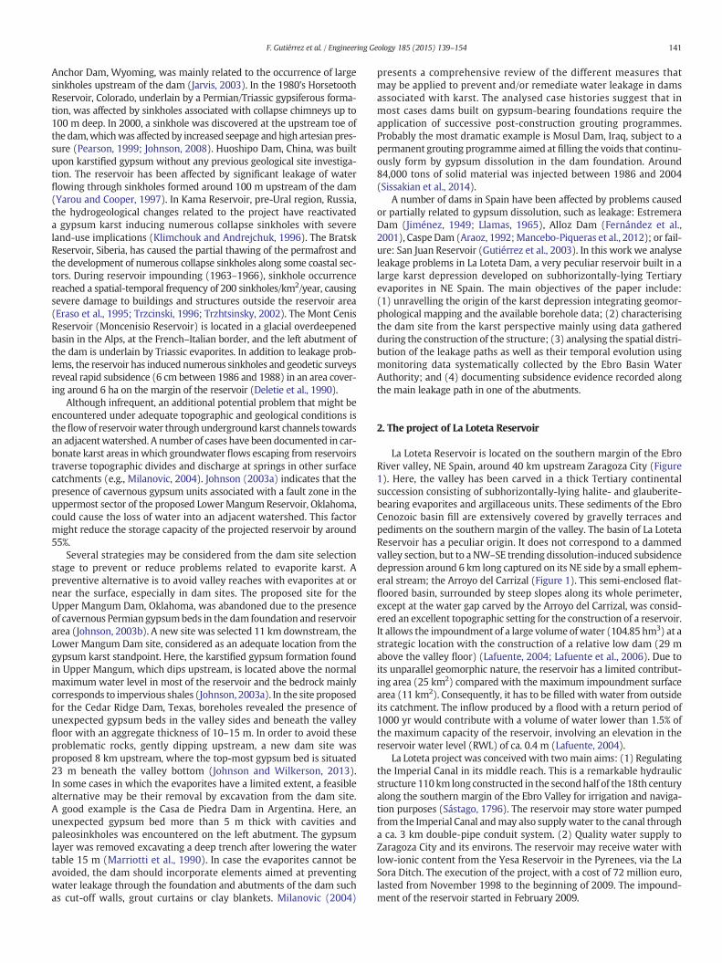
Unit I (subunits 1.1, 1.2, and 1.3 of the reports). The base of this unit,exposed on the valley sides, is situated at 279 m a.s.l. (13 m below thedam crest) and is locally overlain by Quaternary alluvium. It consistsof clays and marls with minor amounts of gypsum (Figure 5).
Unit II (subunit 2.1 of the reports). This unit extends from 279 m to268 m a.s.l. It consists of 11 m of well-stratified gypsumwith interbed-ded marls (Figure 5). In boreholes drilled within the reservoir basin(LO-2 and LO-3) (Figure 6), this unit includes centimetre-thick halitebeds. Large cubic gypsum pseudomorphs after precursor halite were
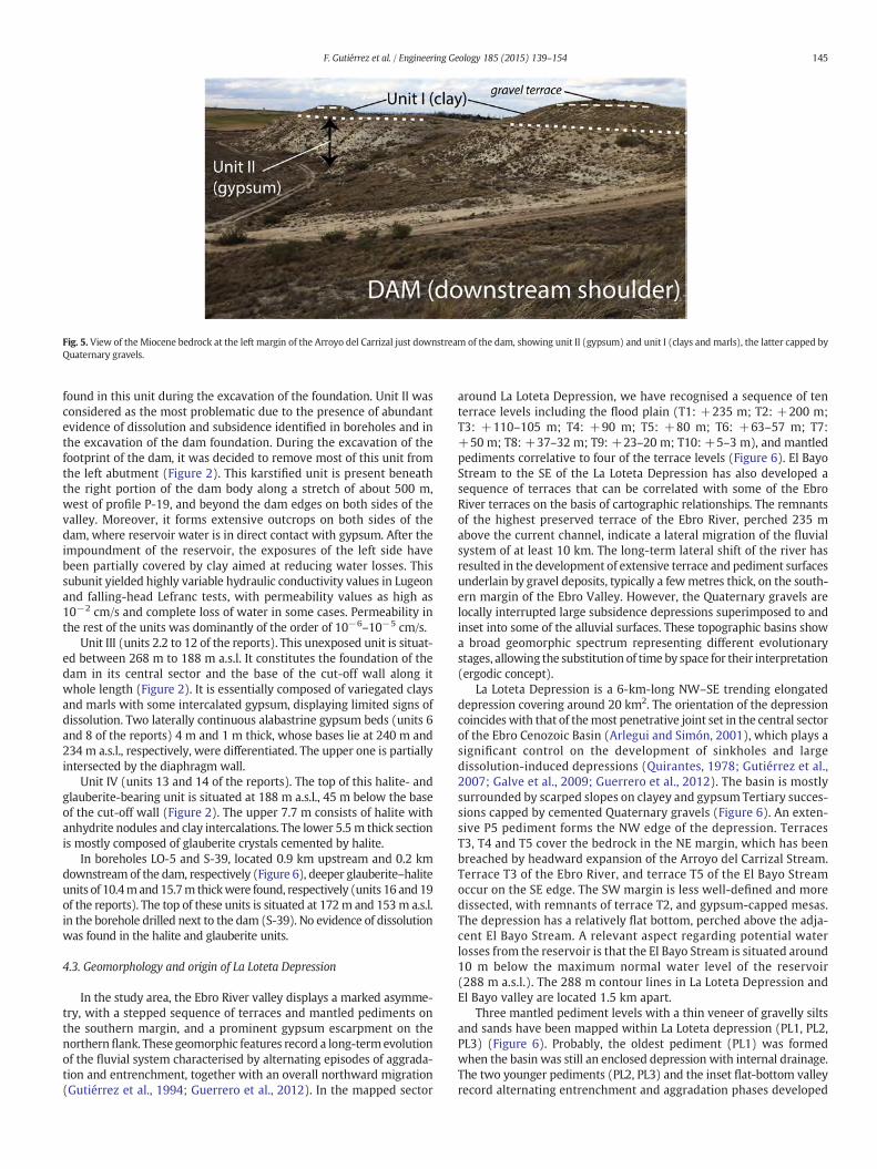
Fig. 5. View of the Miocene bedrock at the left margin of the Arroyo del Carrizal just downstream of the dam, showing unit II (gypsum) and unit I (clays and marls), the latter capped byQuaternary gravels.
145F. Gutiérrez et al. / Engineering Geology 185 (2015) 139–154
found in this unit during the excavation of the foundation. Unit II wasconsidered as the most problematic due to the presence of abundantevidence of dissolution and subsidence identified in boreholes and inthe excavation of the dam foundation. During the excavation of thefootprint of the dam, it was decided to remove most of this unit fromthe left abutment (Figure 2). This karstified unit is present beneaththe right portion of the dam body along a stretch of about 500 m,west of profile P-19, and beyond the dam edges on both sides of thevalley. Moreover, it forms extensive outcrops on both sides of thedam, where reservoir water is in direct contact with gypsum. After theimpoundment of the reservoir, the exposures of the left side havebeen partially covered by clay aimed at reducing water losses. Thissubunit yielded highly variable hydraulic conductivity values in Lugeonand falling-head Lefranc tests, with permeability values as high as10−2 cm/s and complete loss of water in some cases. Permeability inthe rest of the units was dominantly of the order of 10−6–10−5 cm/s.
Unit III (units 2.2 to 12 of the reports). This unexposed unit is situat-ed between 268 m to 188 m a.s.l. It constitutes the foundation of thedam in its central sector and the base of the cut-off wall along itwhole length (Figure 2). It is essentially composed of variegated claysand marls with some intercalated gypsum, displaying limited signs ofdissolution. Two laterally continuous alabastrine gypsum beds (units 6and 8 of the reports) 4 m and 1 m thick, whose bases lie at 240 m and234 m a.s.l., respectively, were differentiated. The upper one is partiallyintersected by the diaphragm wall.
Unit IV (units 13 and 14 of the reports). The top of this halite- andglauberite-bearing unit is situated at 188 m a.s.l., 45 m below the baseof the cut-off wall (Figure 2). The upper 7.7 m consists of halite withanhydrite nodules and clay intercalations. The lower 5.5 m thick sectionis mostly composed of glauberite crystals cemented by halite.
In boreholes LO-5 and S-39, located 0.9 km upstream and 0.2 kmdownstream of the dam, respectively (Figure 6), deeper glauberite–haliteunits of 10.4mand15.7m thickwere found, respectively (units 16 and19of the reports). The top of these units is situated at 172m and 153m a.s.l.in the borehole drilled next to the dam (S-39). No evidence of dissolutionwas found in the halite and glauberite units.
4.3. Geomorphology and origin of La Loteta Depression
In the study area, the Ebro River valley displays a marked asymme-try, with a stepped sequence of terraces and mantled pediments onthe southern margin, and a prominent gypsum escarpment on thenorthernflank. These geomorphic features record a long-termevolutionof the fluvial system characterised by alternating episodes of aggrada-tion and entrenchment, together with an overall northward migration(Gutiérrez et al., 1994; Guerrero et al., 2012). In the mapped sector
around La Loteta Depression, we have recognised a sequence of tenterrace levels including the flood plain (T1: +235 m; T2: +200 m;T3: +110–105 m; T4: +90 m; T5: +80 m; T6: +63–57 m; T7:+50 m; T8: +37–32 m; T9: +23–20 m; T10: +5–3 m), and mantledpediments correlative to four of the terrace levels (Figure 6). El BayoStream to the SE of the La Loteta Depression has also developed asequence of terraces that can be correlated with some of the EbroRiver terraces on the basis of cartographic relationships. The remnantsof the highest preserved terrace of the Ebro River, perched 235 mabove the current channel, indicate a lateral migration of the fluvialsystem of at least 10 km. The long-term lateral shift of the river hasresulted in the development of extensive terrace and pediment surfacesunderlain by gravel deposits, typically a fewmetres thick, on the south-ern margin of the Ebro Valley. However, the Quaternary gravels arelocally interrupted large subsidence depressions superimposed to andinset into some of the alluvial surfaces. These topographic basins showa broad geomorphic spectrum representing different evolutionarystages, allowing the substitution of time by space for their interpretation(ergodic concept).
La Loteta Depression is a 6-km-long NW–SE trending elongateddepression covering around 20 km2. The orientation of the depressioncoincideswith that of themost penetrative joint set in the central sectorof the Ebro Cenozoic Basin (Arlegui and Simón, 2001), which plays asignificant control on the development of sinkholes and largedissolution-induced depressions (Quirantes, 1978; Gutiérrez et al.,2007; Galve et al., 2009; Guerrero et al., 2012). The basin is mostlysurrounded by scarped slopes on clayey and gypsum Tertiary succes-sions capped by cemented Quaternary gravels (Figure 6). An exten-sive P5 pediment forms the NW edge of the depression. TerracesT3, T4 and T5 cover the bedrock in the NE margin, which has beenbreached by headward expansion of the Arroyo del Carrizal Stream.Terrace T3 of the Ebro River, and terrace T5 of the El Bayo Streamoccur on the SE edge. The SW margin is less well-defined and moredissected, with remnants of terrace T2, and gypsum-capped mesas.The depression has a relatively flat bottom, perched above the adja-cent El Bayo Stream. A relevant aspect regarding potential waterlosses from the reservoir is that the El Bayo Stream is situated around10 m below the maximum normal water level of the reservoir(288 m a.s.l.). The 288 m contour lines in La Loteta Depression andEl Bayo valley are located 1.5 km apart.
Three mantled pediment levels with a thin veneer of gravelly siltsand sands have been mapped within La Loteta depression (PL1, PL2,PL3) (Figure 6). Probably, the oldest pediment (PL1) was formedwhen the basin was still an enclosed depression with internal drainage.The two younger pediments (PL2, PL3) and the inset flat-bottom valleyrecord alternating entrenchment and aggradation phases developed
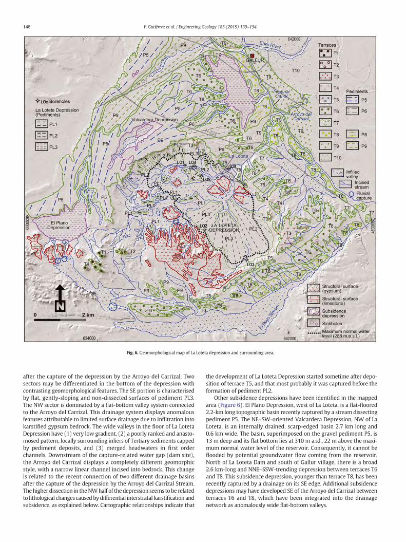
Fig. 6. Geomorphological map of La Loteta depression and surrounding area.
146 F. Gutiérrez et al. / Engineering Geology 185 (2015) 139–154
after the capture of the depression by the Arroyo del Carrizal. Twosectors may be differentiated in the bottom of the depression withcontrasting geomorphological features. The SE portion is characterisedby flat, gently-sloping and non-dissected surfaces of pediment PL3.The NW sector is dominated by a flat-bottom valley system connectedto the Arroyo del Carrizal. This drainage system displays anomalousfeatures attributable to limited surface drainage due to infiltration intokarstified gypsum bedrock. The wide valleys in the floor of La LotetaDepression have (1) very low gradient, (2) a poorly ranked and anasto-mosed pattern, locally surrounding inliers of Tertiary sediments cappedby pediment deposits, and (3) merged headwaters in first orderchannels. Downstream of the capture-related water gap (dam site),the Arroyo del Carrizal displays a completely different geomorphicstyle, with a narrow linear channel incised into bedrock. This changeis related to the recent connection of two different drainage basinsafter the capture of the depression by the Arroyo del Carrizal Stream.Thehigher dissection in theNWhalf of the depression seems to be relatedto lithological changes causedbydifferential interstratal karstification andsubsidence, as explained below. Cartographic relationships indicate that
the development of La Loteta Depression started sometime after depo-sition of terrace T5, and that most probably it was captured before theformation of pediment PL2.
Other subsidence depressions have been identified in the mappedarea (Figure 6). El Plano Depression, west of La Loteta, is a flat-floored2.2-km long topographic basin recently captured by a stream dissectingpediment P5. The NE–SW-oriented Valcardera Depression, NW of LaLoteta, is an internally drained, scarp-edged basin 2.7 km long and0.6 km wide. The basin, superimposed on the gravel pediment P5, is13 m deep and its flat bottom lies at 310 m a.s.l., 22 m above the maxi-mum normal water level of the reservoir. Consequently, it cannot beflooded by potential groundwater flow coming from the reservoir.North of La Loteta Dam and south of Gallur village, there is a broad2.6 km-long and NNE–SSW-trending depression between terraces T6and T8. This subsidence depression, younger than terrace T8, has beenrecently captured by a drainage on its SE edge. Additional subsidencedepressions may have developed SE of the Arroyo del Carrizal betweenterraces T6 and T8, which have been integrated into the drainagenetwork as anomalously wide flat-bottom valleys.
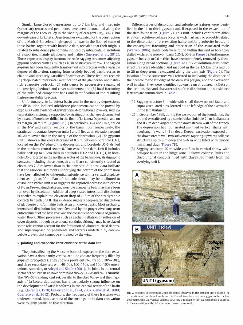
Fig. 7. Evidence of dissolution and subsidence observed in the gypsum unit II during theexcavation of the dam foundation. A. Dissolution focused on a gypsum bed a fewdecimetres thick. B. Vertical collapse structure 9 m deep within paleosinkhole 2 exposedin the excavation at the left abutment, downstream wall.
147F. Gutiérrez et al. / Engineering Geology 185 (2015) 139–154
Similar large closed depressions up to 7 km long and inset intoQuaternary terraces and pediments have been documented along themargins of the Ebro Valley in the vicinity of Zaragoza City, 30–60 kmdownstream of La Loteta. Deep trenches excavated for the constructionof the Madrid-Barcelona high-speed railway in the floor of some ofthose basins, together with borehole data, revealed that their origin isrelated to subsidence phenomena induced by interstratal dissolutionof evaporites, mainly glauberite and halite (Guerrero et al., 2012).Those exposures display hectometre-scale sagging structures affectinggypsum bedrock with as much as 10 m of structural throw. The saggedgypsum has been frequently transformed into breccias with a variabledegree of distortion, ranging from crudely bedded packbreccias tochaotic and intensely karstified floatbreccias. These features record:(1) deep-seated interstratal karstification of the glauberite- and halite-rich evaporite bedrock; (2) subsidence by progressive sagging ofthe overlying bedrock and cover sediments; and (3) local fracturingof the subsided competent beds and karstification of the resultinghigh-permeability breccias.
Unfortunately, in La Loteta basin and in the nearby depressions,the dissolution-induced subsidence phenomena cannot be proved byexposureswith evidence of gravitational deformation. However, such in-terpretation is strongly supported by stratigraphic changes documentedbymeans of boreholes drilled in the floor of La Loteta Depression and onits margin (dam site) (Figure 6): (1) In boreholes LO-4 and LO-2, drilledin the NW and central sectors of the basin floor, respectively, thestratigraphic contact between units I and II lies at an elevation around10–20 m lower than in the margin of the depression. (2) The gypsumunit II shows a thickness decrease of 8.6 m between borehole LO-3,located on the SW edge of the depression, and borehole LO-5, drilledin the northern-central sector, 0.9 km west of the dam. Unit II includeshalite beds up to 10 cm thick in boreholes LO-2 and LO-3. (3) In bore-hole LO-5, located in the northern sector of the basin floor, stratigraphiccontacts, including those beneath unit II, are consistently situated atelevations 7–8 m lower than in the dam site. All these data indicatethat the Miocene sediments underlying the bottom of the depressionhave been affected by differential subsidence with a vertical displace-ment as high as 20 m. Part of that subsidence may be attributed todissolutionwithin unit II, as suggests the reported decrease in thicknessof 8.6m. Pre-existing halite and possible glauberite bedsmay have beenremoved by dissolution. Additional deep-seated interstratal dissolutionis needed to explain the elevation drop of 7–8 m of the stratigraphiccontacts beneath unit II. This evidence suggests deep-seated dissolutionof glauberite and/or halite beds at an unknown depth. Most probably,interstratal dissolution has been favoured by the progressive long-termentrenchment of the base level and the consequent deepening of ground-water flows. Other processes such as aeolian deflation or suffosion ofcover deposits through dissolutional conduits, althoughmay have playedsome role, cannot account for the formation of kilometre-sized depres-sion superimposed on pediments and terraces underlain by cobble–pebble gravels that cannot be entrained by the wind.
5. Jointing and evaporite karst evidence at the dam site
The joints affecting the Miocene bedrock exposed in the dam exca-vation have a dominantly vertical attitude and are frequently filled bygypsum precipitates. They show a prevalent N–S trend (10W–10E),and three secondary sets with 40–50E, 100–110E, and 150–160E orien-tations. According to Arlegui and Simón (2001), the joints in the centralsector of the Ebro Basin have dominantNW–SE, E–WandN–S azimuths.The NW–SE trending joint set, parallel to the Ebro Valley and the majoraxis of La Loteta depression, has a particularly strong influence onthe development of karst landforms in the central sector of the basin(e.g., Quirantes, 1978; Gutiérrez et al., 1994, 2007; Galve et al., 2009;Guerrero et al., 2012). Probably, the frequency of these fractures wasunderestimated, because most of the cuttings in the dam excavationwere roughly parallel to that direction.
Different types of dissolution and subsidence features were identi-fied in the 11 m thick gypsum unit II exposed in the excavation ofthe dam foundation (Figure 7). This unit includes centimetre-thickstratiform solution–collapse brecciaswithmarlmatrix, probably relatedto the dissolution of pre-existing halite and/or glauberite beds, andthe consequent fracturing and brecciation of the associated rocks(Warren, 2006). Halite beds were found within this unit in boreholesdrilled within the reservoir basin (LO-2, LO-3 in Figure 6). Furthermore,gypsumbeds up to 0.6m thick have been completely removed by disso-lution along broad sections (Figure 7A). Six dissolution–subsidencestructures were identified and mapped in the ca. 1.5 km long and upto 20 m deep trench excavated along the dam axis (Figure 2). Thelocation of these structures was referred to indicating the distance oftheir centre to the left edge of the dam axis (origin) and the excavationwall in which they were identified (downstream or upstream). Data onthe location, size and characteristics of the dissolution and subsidencefeatures are summarised in Table 1.
(1) Sagging structure 3 m wide with small-throw normal faults andsupra-attenuated dips, located at the left edge of the excavationin the left abutment.
(2) In September 1999, during the excavation of the foundation, theground was affected by a semicircular sinkhole 24m in diameterand 0.7 m deep adjacent to the downstream wall of the trench.The depression had four nested air-filled vertical shafts withoverhanging walls 1–3 m deep. Deeper excavation exposed onthe downstreamwall two subvertical tapering-upwards collapsestructures up to 9 m deep and 5–6 m wide filled with chaoticmarls, and clays (Figure 7B).
(3) Sagging structure 20 m wide and 5 m in vertical throw withcollapse faults in the hinge zone. It shows collapse faults anddissolutional conduits filled with clayey sediments from theoverlying unit I.
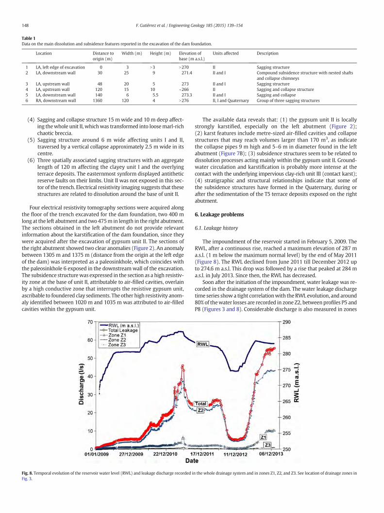
Table 1Data on the main dissolution and subsidence features reported in the excavation of the dam foundation.
Location Distance toorigin (m)
Width (m) Height (m) Elevation ofbase (m a.s.l.)
Units affected Description
1 LA, left edge of excavation 0 3 N3 N270 II Sagging structure2 LA, downstream wall 30 25 9 271.4 II and I Compound subsidence structure with nested shafts
and collapse chimneys3 LA, upstream wall 48 20 5 273 II and I Sagging structure4 LA, upstream wall 120 15 10 ~266 II Sagging and collapse structure5 LA, downstream wall 140 6 5.5 273.3 II and I Sagging and collapse6 RA, downstream wall 1360 120 4 N276 II, I and Quaternary Group of three sagging structures
148 F. Gutiérrez et al. / Engineering Geology 185 (2015) 139–154
(4) Sagging and collapse structure 15 m wide and 10 m deep affect-ing thewhole unit II, whichwas transformed into loosemarl-richchaotic breccia.
(5) Sagging structure around 6 m wide affecting units I and II,traversed by a vertical collapse approximately 2.5 m wide in itscentre.
(6) Three spatially associated sagging structures with an aggregatelength of 120 m affecting the clayey unit I and the overlyingterrace deposits. The easternmost synform displayed antitheticreserve faults on their limbs. Unit II was not exposed in this sec-tor of the trench. Electrical resistivity imaging suggests that thesestructures are related to dissolution around the base of unit II.
Four electrical resistivity tomography sections were acquired alongthe floor of the trench excavated for the dam foundation, two 400 mlong at the left abutment and two 475m in length in the right abutment.The sections obtained in the left abutment do not provide relevantinformation about the karstification of the dam foundation, since theywere acquired after the excavation of gypsum unit II. The sections ofthe right abutment showed two clear anomalies (Figure 2). An anomalybetween 1305 m and 1375 m (distance from the origin at the left edgeof the dam) was interpreted as a paleosinkhole, which coincides withthe paleosinkhole 6 exposed in the downstreamwall of the excavation.The subsidence structurewas expressed in the section as a high resistiv-ity zone at the base of unit II, attributable to air-filled cavities, overlainby a high conductive zone that interrupts the resistive gypsum unit,ascribable to foundered clay sediments. The other high resistivity anom-aly identified between 1020 m and 1035 m was attributed to air-filledcavities within the gypsum unit.
Fig. 8. Temporal evolution of the reservoir water level (RWL) and leakage discharge recorded iFig. 3.
The available data reveals that: (1) the gypsum unit II is locallystrongly karstified, especially on the left abutment (Figure 2);(2) karst features include metre-sized air-filled cavities and collapsestructures that may reach volumes larger than 170 m3, as indicatethe collapse pipes 9 m high and 5–6 m in diameter found in the leftabutment (Figure 7B); (3) subsidence structures seem to be related todissolution processes acting mainly within the gypsum unit II. Ground-water circulation and karstification is probably more intense at thecontact with the underlying impervious clay-rich unit III (contact karst);(4) stratigraphic and structural relationships indicate that some ofthe subsidence structures have formed in the Quaternary, during orafter the sedimentation of the T5 terrace deposits exposed on the rightabutment.
6. Leakage problems
6.1. Leakage history
The impoundment of the reservoir started in February 5, 2009. TheRWL, after a continuous rise, reached a maximum elevation of 287 ma.s.l. (1 m below the maximum normal level) by the end of May 2011(Figure 8). The RWL declined from June 2011 till December 2012 upto 274.6 m a.s.l. This drop was followed by a rise that peaked at 284 ma.s.l. in July 2013. Since then, the RWL has decreased.
Soon after the initiation of the impoundment, water leakage was re-corded in the drainage system of the dam. The water leakage dischargetime series show a tight correlationwith the RWL evolution, and around80% of thewater losses are recorded in zone Z2, between profiles P5 andP8 (Figures 3 and 8). Considerable discharge is also measured in zones
n the whole drainage system and in zones Z1, Z2, and Z3. See location of drainage zones in

149F. Gutiérrez et al. / Engineering Geology 185 (2015) 139–154
Z1 and Z3, whereas total water loss rate is lower than 10 l/s in the re-maining zones. In April 2011, when the reservoir reached its maximumhistorical level, the total leakage reached 46 l/s, of which 37.5 l/s and6.9 l/s were collected in zones Z2 and Z1, respectively. This must beconsidered as a minimum estimate of the water losses, since seepagewas identified at several sites downstream of the dam.
During the second phase of RWL rise, leakage discharge increasedabruptly and has remained at higher values than in April 2011, despitethe lower RWL (Figure 8). Since July 2013, although the RWL has slight-ly declined, leakage rate has increased steadily, reaching 55.5 l/s inJanuary 2014, at a RWL of 283.3 m a.s.l. At this time, leakage rate was9.5 l/s higher than that measured when the RWL was at its historicalmaximum, 3.7 m above. These data indicate that leakage water comesfrom the reservoir and suggests that there has been an increase in per-meability related to the enlargement and/or generation of conduits bydissolution and internal erosion of sediments filling pre-existing voids.
Pore water pressure is systematically measured in the dam founda-tion, clay core and clay blanket by means of vibrating wire piezometersinstalled in the eight monitoring profiles perpendicular to the dam axis(see location of piezometers at profile P7 in Figure 3). The piezometricdata collected at profile P7 indicate that there is no leakage throughthe dam body in zone Z2, despite its drainage system collects a greatpart of the water losses (Figure 9): (1) piezometers installed in theclay core (PZ7-272, PZ7-273 and PZ7-274) record nearly constantporewater pressurewithout any correlationwith the RWL; (2) piezom-eter PZ7-272 in the upstream sector of the clay core, records lowerwater pressure than piezometer PZ7-273 located downstream in theclay core; (3) negative pore water pressure (unsaturated conditions)is measured in the piezometer located within the clay core furtherdownstream (PZ7-274).
The piezometers at profile P7 that measure pore water pressure inthe dam foundation, just downstream of the cut-off wall, show negligi-ble correlation with reservoir water level (PZ7-1, PZ7-2, PZ7-3 in Figure9). Potential water leakage through the dam foundation towards thedrainage system in zone Z2 should be recorded in the boreholes locateddownstream (PB5a, PB5b, PB7a and PB 7b in Figure 10). However, waterlevel changes of those boreholes do not show any correspondence withwater pressure recorded in the electrical piezometers of profile P7.In profiles P13 and P17 (Figure 3),water pressuremeasured in the foun-dation near the cut-off wall is significantly higher than those in profileP7, but water leakage in the drainage system is negligible.
Fig. 9. Temporal evolution of the reservoir water level (RWL) andwater level time series recordthe lack of correlation between both datasets.
As explained in the next section, piezometric data reveals thatwaterfrom the reservoir flows through bedrock and the grout curtain at theleft abutment beyond the cut-off wall, which shows a good perfor-mance. The reason why the highest discharge is measured in zone Z2,rather than in zone Z1, may be attributed to the design of the drainagesystem (Figures 2 and 3). In zone Z1 the footprint of the dam and thedrainage pipe has a 3% inclination towards zone Z2. This gradient allowsa great part of the leakage water to pass through this zone along thedrain. In zone Z2, where the pipe is nearly horizontal, with a slight re-verse inclination towards zone Z1 (Figure 2), leakage water reducesits flow velocity and can be effectively collected by the drainage system.
6.2. Main leakage paths
The good temporal correlation between the RWL and both waterlevel changes recorded in boreholes downstream of the dam and theoccurrence of seepages, indicate effective hydraulic connection betweenthe reservoir and the downstream sector. Several alternatives may beconsidered for the water losses:
(1) Water flow in the abutments below the grout curtain. In bothabutments, the base of the grout curtain is 8 m deeper thanthe base of gypsum unit II. It is unlikely to have any significantleakage through the clayey unit III (Figure 2).
(2) Through Tertiary bedrock beyond the end of the grout curtain.Water from the reservoir might escape through the gypsumunit II, exposed all along the NE margin of the reservoir. Voidsmay be also present in the overlying clay unit I, related to subsi-dence processes caused by the karstification of the underlyingunit. The shortest distance between the impounded water atRWL of 287 m a.s.l. (historical maximum) and the left and rightabutments is 680 m and 175 m, respectively (Figure 10). Conse-quently, there is a higher hydraulic gradient at the right abut-ment and a priori greater leakage potential. Fig. 11 shows thatthe RWL raises have caused very small water level ascents inborehole PZ4b located at the end of the grout curtain in the leftabutment. Here, the maximum RWL raise (287 m a.s.l.) causedan elevation of 3.5 m in the groundwater level, with a hydraulichead loss of 13 m. In case there would be a significant flow, alower hydraulic head difference would be expected. Moreover,no seepage points have been detected downstream of borehole
ed by piezometers installed in the clay core, clay blanket and foundation at profile P7. Note

Fig. 10. A. Equipotential map constructed with water level data measured in boreholes and the elevation of seepage points recorded in July 2011, when the RWL was at 285 m a.s.l. Thelocation of the sinkholes and sinkhole clusters identified in the reservoir area, upstream the left abutment, are indicated with stars. B. Enlarged map of the left abutment.
150 F. Gutiérrez et al. / Engineering Geology 185 (2015) 139–154
PZ4b. Unfortunately, at the right abutment, there is no boreholeat the end of the grout curtain. Therefore, it is not possible toelucidate whether there is any considerable water loss in thatsector, despite that there is potentially higher probability thanin the left abutment due to shorter distance and higher gradient.
(3) Water leakage through the grout curtain. The water levelsrecorded in pairs of monitoring boreholes at both sides thegrout curtain reveal that there is significant water flow acrossthe grout curtain in both abutments (Figure 11). The highlyvariable water level differences in the borehole pairs allow theidentification of sections with relatively higher leakage rates. Atthe right abutment, the water level difference in borehole pairsPZ11–PZ1D and PZ21–PZ2D was less than 1.2 m when the RWL
was at 287 m a.s.l. (Figures 10A and 11). In the left abutment,borehole pairs PZ5a–PZ5b, PZ6a–PZ6b, PZ7a–PZ7b, PZ8a–PZ8b,and PZ2a–PZ2b show a head difference as low as 2 m. Thesedata indicate inadequate performance of the grout curtain atboth abutments. The water level differences in borehole pairPZ1a–PZ1bwas 12.5m (Figure 11). This difference, much higherthan in the nearby boreholes PZ2a and PZ2b, can be explained bya rapid downward flow from PZ1b towards the pervious drain-age system of the dam (Figure 10B).
An equipotential map has been constructed using water levels mea-sured in 47 boreholes and the elevation of seepage points recorded in

Fig. 11. Temporal variation of RWL and groundwater levelsmeasured in several borehole pairs located in the right abutment (PZ11–PZ1D), at the left edge of the dam (PZ1a–PZ1b), in thecentral sector of the left grout curtain (PZ6a–PZ6b), and at the edge of the left curtain (PZ4b). See location of boreholes in Figure 10.
151F. Gutiérrez et al. / Engineering Geology 185 (2015) 139–154
July 2011, when the RWL was at 285 m a.s.l. after reaching its historicalmaximum (Figure 10). The isopleths map was generated with the 3DAnalyst of ArcGIS after defining the boundaries of the area, consideringthe spatial distribution of the available data. Although this map justdepicts a schematic picture of the actual groundwater level, it providesuseful clues on the main leakage paths.
In the left abutment, the equipotential lines indicate that water flowthrough the grout curtain mainly occurs between the dam body andthe pair of borehole PZ5. Two main flow paths may be differentiated.A general one centred around borehole pairs PZ6 and PZ7, produces adiverging water flow towards the base level. Boreholes in this sectorhave a similar response to the RWL variations (Figure 11), and the am-plitude of the water level consistently attenuates along the flow lines.There is also a major leakage path associated with the left edge of thedam, where a gap in the watertightness system has been detected.When the RWL was at 285 m a.s.l., water level in borehole PZ2b was0.5 m higher than in PZ1b, indicating water flow towards the edge ofthe dam. Water level data recorded in the boreholes downstream ofthe dam show a good correlation with the RWL (Figure 11) and definea trough in the equipotential surface, suggesting flow towards the seep-age zones and the drainage system of the dam (Figure 10B). Part of theleakage water most probably flows through the foundation beneath thedam body, as support the high grout absorption recorded in the twoboreholes drilled 4 m SE of profile P1 in 2013 (Figure 4), and the anom-alously high settlement measured by levelling in the crest of the damaround profile P1 (Figure 2).
At the right abutment, the equipotential lines suggest higher waterloss through the grout curtain close to the edge of the dam and aroundborehole PZ1D (Figure 10A).Water levels in boreholes and the distribu-tion of seepage zones indicate a main flow path towards the rightmargin of the valley. During the period when the RWL reached themaximum, significant water discharge occurred in the tributary drain-age located downstream of the dam NW of borehole PZ22d, where aherringbone drainage system was constructed to prevent waterloggingin crop fields.
7. Evidence of active subsidence at the left abutment
In September 2011, a collapse sinkhole was detected on the leftabutment just upstream of the dam body (sinkhole 1 in Figure 10).
The collapse affected a slope covered by rip-rap. Probably the sinkholewas formed beneath the water sometime before and it passed unno-ticed until it was exposed by the water level decline. On 27 March2014 the circular sinkhole was 4.3 m wide and 1 m deep (Figure 12A).
Periodic levelling measurements are obtained along the crest of thedam. The settlement time series inmost of the levelling points show theexpectable gradual subsidence proportional to the dam height, with adecreasing temporal trend related to compaction. However, point N1located on profile P1, and point N2 situated 25 m to the SE, show theopposite trend since September 2010 (Figure 13). On February 2014,cumulative settlement had reached around 0.08% of the dam height inall of the levelling points, except in N1 and N2 where it amounts0.24% and 0.16%, respectively. The subsidence time series show that inpoints N1 and N2, the common attenuation of the deformation ratechanged since September 2010 to a subsidence acceleration phase.The average subsidence rate measured in points N1 and N2 betweenJune 2007 and September 2010 was 4.6 mm/yr and 5.6 mm/yr, respec-tively. Between September 2010 and February 2014 the vertical defor-mation rate increased to 13.8 mm/yr and 8.6 mm/yr in points N1 andN2, respectively.
By the end of March 2014, during a RWL decline, three new sink-holes or sinkhole clusters were detected in the left abutment upstreamof the damwithin a NNE–SSW band around 100m long (see location inFigure 10). Sinkhole 2 was a small collapse 0.7 m long and 0.4 m deeplocated 18 m upstream of the base of the shoulder. Sinkhole cluster 3,located 25m upstreamof the dam,was also composed by two fresh col-lapses 1.5 m across and 4.5m long. These sinkholes where embraced byopen cracks with a subcircular pattern around 9 m across (Figure 12B).Sinkhole cluster 4 comprised a circular and an elongated collapse 1.5 macross and 4 m long, respectively (Figure 12C). The overhanging edgesof the depressions and the fresh cracks associated with them suggestthat these sinkholes will keep on enlarging and coalescing.
All these data, consistent with the high grout absorption valuesrecorded in the boreholes conducted in 2013, the gap detected in thewaterproofing system, and the equipotential map, indicate that thereis substantial water leakage at the left abutment next to and beneaththe dam body. This water flow, as suggested by the increasing leakagedischarge despite the declining RWL, is most probably enlargingconduits by dissolution and internal erosion, leading to the settlementof the dam body and the occurrence of sinkholes.

Fig. 12. Photographs taken on 27March 2014 of sinkholes formed at the left abutmentupstream of the dam. A. Collapse sinkhole 1 with a diameter of 4.3 m detected inSeptember 2011 affecting the rip-rap next to left edge of the dam body. B. Sinkholecluster 3. C. Sinkhole cluster 4.
152 F. Gutiérrez et al. / Engineering Geology 185 (2015) 139–154
8. Discussion and conclusions
La Loteta Reservoir is located in a unique geological setting; a largesubsidence depression around 6 km long resulting from interstratalkarstification of halite- and glauberite-bearing evaporites. The damsite corresponds to the water gap carved by the small drainage thatcaptured the previously internally drained basin, covering around20 km2. This is the largest karst depression documented so far in theextensive evaporite terrains of the central sector of the Ebro CenozoicBasin. Moreover, to our knowledge, La Loteta Reservoir, together withCarter Lake, Colorado, are the only artificial lakes placed on evaporitedissolution-induced basins reported in the literature. Carter Reservoirin the Colorado Front Range was built on an enclosed subsidence de-pression 3 km long and 1.5 km wide related to dissolution of Permian-Triassic gypsiferous strata. The natural lake used to drain undergroundfeeding a spring outside the basin. At the present time, leakage waterfrom the reservoir emerges in the former natural spring with a flow
rate of over 110 l/s and is nearly saturated with respect to gypsum(Pearson, 1999).
The impoundment of reservoirs involves creating unprecedented andunnatural high hydraulic gradients that may lead to water leakagethrough karstified rocks. Underground flows escaping from the reservoirmay flush out the deposits that plug karst conduits and enlarge disconti-nuities and cavities by dissolution, with the consequent permeability in-crease in a self-accelerating process (James, 1992; Romanov et al., 2003;Milanovic, 2004; Johnson, 2008; Gutiérrez, 2010; Cooper and Gutiérrez,2013). Moreover, impounded water in direct contact with evaporiteoutcrops may rapidly dissolve the karst rocks, with the consequenthydrochemical degradation of the stored water. In areas with steeplydipping sedimentary successions, karst rocks associated with dam sitesand reservoirs commonly form restricted outcrops or bands. Many damsites are located at valley constrictions related to dipping carbonateunits striking perpendicularly or obliquely to the valley (Milanovic,2004). In these situations, the spatial distribution of potential leakagezones and the layout of grout curtains may be constrained withconfidence on the basis of geological data. However, in areas withsubhorizontally-lying successions, the soluble rock units may occuralong thewhole perimeter of the reservoir basin. In the case of La LotetaReservoir, there is a subhorizontal gypsum unit with limited thickness(11 m), but distributed all around the basin. Therefore, water has thepotential to flow away from the reservoir through the gypsum unitalong extensive sectors, especially at the NE margin of the reservoirwhere the dam is located. Although unlikely, there is also the possibilityfor the water to escape through the SE margin towards the adjacentEl Bayo Stream (Figure 6). This channel is located 10 m below themaximum water level of the reservoir (288 m a.s.l.) and the distancebetween that contour line in the reservoir and the valley is 1.5 km. Inthis type of contexts, the design and construction of grout curtainsface two significant problems: (1) a lack of a lateral boundary in thekarstified unit with an impervious rock to establish the desirable edgeof the curtain; and (2) the probable need of building long costly groutcurtains to assure the watertightness of the reservoir.
Preferably, grout curtains should be oriented perpendicularly to theexpected underground flow direction and should be built into imper-meable rocks. In La Loteta Dam, 675 m and 255 m long grout curtainswere built on the left and right abutments, respectively. These curtainspenetrate into the clayey sediments underlying the gypsum unit, but itwas not possible to tie their edges to impervious sediments due thelateral extension of the gypsum unit. The longer curtain at the leftabutment, where the gypsum showed significantly more evidence ofkarstification, has a curved trace with a significant downstream deflec-tion from the orientation of the dam. This geometry, conditioned byland ownership constraints, may limit the desirable performance of agrout curtain with such length.
The available data indicate that water leakage occurs through the11 m thick gypsum unit II exposed in the dam site and along the NEmargin of the basin. Fortunately, the highly soluble halite and glauberiteunit located 70 m and 45 m below the dam body and the cut-off wall,respectively, does not seem to have been affected by water leakagefrom the reservoir. Remediation in such a scenario would be very difficultand uncertain due to the extremely high solubility of halite (360 g/l) andglauberite (118 g/l). The 80m thick argillaceous unit III situated betweenthe gypsumunit II and the salt unit IV is acting as an effective bottom sealfor the groundwater flow derived from the reservoir.
Themost important leakage occurs at the left abutment beneath andnext to the edge of the dam body, as support the following lines of evi-dence: (1) The excavation of the dam foundation showed amuchhigherdensity of dissolution and subsidence features in the left abutment(Figures 2 and 7). (2) The gypsum unit was not completely removedfrom beneath the left edge of the dam body (Figure 2). (3) The highgrout takes recorded in this sector before and after impoundment indi-cate the presence of cavernous gypsum with metre-sized cavities(Figure 4). (4) An intricate gap is detected between the clay blanket
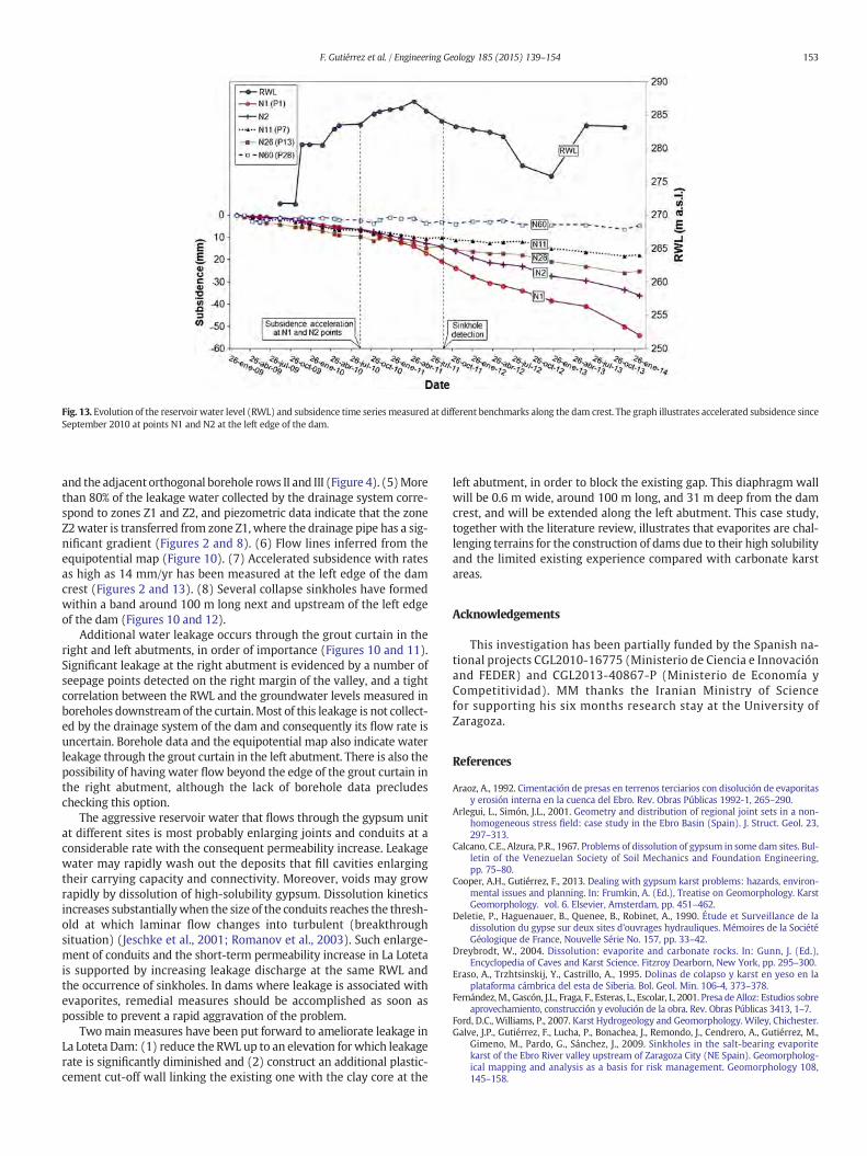
Fig. 13. Evolution of the reservoir water level (RWL) and subsidence time series measured at different benchmarks along the dam crest. The graph illustrates accelerated subsidence sinceSeptember 2010 at points N1 and N2 at the left edge of the dam.
153F. Gutiérrez et al. / Engineering Geology 185 (2015) 139–154
and the adjacent orthogonal borehole rows II and III (Figure 4). (5)Morethan 80% of the leakage water collected by the drainage system corre-spond to zones Z1 and Z2, and piezometric data indicate that the zoneZ2water is transferred from zone Z1, where the drainage pipe has a sig-nificant gradient (Figures 2 and 8). (6) Flow lines inferred from theequipotential map (Figure 10). (7) Accelerated subsidence with ratesas high as 14 mm/yr has been measured at the left edge of the damcrest (Figures 2 and 13). (8) Several collapse sinkholes have formedwithin a band around 100 m long next and upstream of the left edgeof the dam (Figures 10 and 12).
Additional water leakage occurs through the grout curtain in theright and left abutments, in order of importance (Figures 10 and 11).Significant leakage at the right abutment is evidenced by a number ofseepage points detected on the right margin of the valley, and a tightcorrelation between the RWL and the groundwater levels measured inboreholes downstreamof the curtain.Most of this leakage is not collect-ed by the drainage system of the dam and consequently its flow rate isuncertain. Borehole data and the equipotential map also indicate waterleakage through the grout curtain in the left abutment. There is also thepossibility of having water flow beyond the edge of the grout curtain inthe right abutment, although the lack of borehole data precludeschecking this option.
The aggressive reservoir water that flows through the gypsum unitat different sites is most probably enlarging joints and conduits at aconsiderable rate with the consequent permeability increase. Leakagewater may rapidly wash out the deposits that fill cavities enlargingtheir carrying capacity and connectivity. Moreover, voids may growrapidly by dissolution of high-solubility gypsum. Dissolution kineticsincreases substantiallywhen the size of the conduits reaches the thresh-old at which laminar flow changes into turbulent (breakthroughsituation) (Jeschke et al., 2001; Romanov et al., 2003). Such enlarge-ment of conduits and the short-term permeability increase in La Lotetais supported by increasing leakage discharge at the same RWL andthe occurrence of sinkholes. In dams where leakage is associated withevaporites, remedial measures should be accomplished as soon aspossible to prevent a rapid aggravation of the problem.
Twomain measures have been put forward to ameliorate leakage inLa Loteta Dam: (1) reduce the RWL up to an elevation for which leakagerate is significantly diminished and (2) construct an additional plastic-cement cut-off wall linking the existing one with the clay core at the
left abutment, in order to block the existing gap. This diaphragm wallwill be 0.6 m wide, around 100 m long, and 31 m deep from the damcrest, and will be extended along the left abutment. This case study,together with the literature review, illustrates that evaporites are chal-lenging terrains for the construction of dams due to their high solubilityand the limited existing experience compared with carbonate karstareas.
Acknowledgements
This investigation has been partially funded by the Spanish na-tional projects CGL2010-16775 (Ministerio de Ciencia e Innovaciónand FEDER) and CGL2013-40867-P (Ministerio de Economía yCompetitividad). MM thanks the Iranian Ministry of Sciencefor supporting his six months research stay at the University ofZaragoza.
References
Araoz, A., 1992. Cimentación de presas en terrenos terciarios con disolución de evaporitasy erosión interna en la cuenca del Ebro. Rev. Obras Públicas 1992-1, 265–290.
Arlegui, L., Simón, J.L., 2001. Geometry and distribution of regional joint sets in a non-homogeneous stress field: case study in the Ebro Basin (Spain). J. Struct. Geol. 23,297–313.
Calcano, C.E., Alzura, P.R., 1967. Problems of dissolution of gypsum in some dam sites. Bul-letin of the Venezuelan Society of Soil Mechanics and Foundation Engineering,pp. 75–80.
Cooper, A.H., Gutiérrez, F., 2013. Dealing with gypsum karst problems: hazards, environ-mental issues and planning. In: Frumkin, A. (Ed.), Treatise on Geomorphology. KarstGeomorphology. vol. 6. Elsevier, Amsterdam, pp. 451–462.
Deletie, P., Haguenauer, B., Quenee, B., Robinet, A., 1990. Étude et Surveillance de ladissolution du gypse sur deux sites d'ouvrages hydrauliques. Mémoires de la SociétéGéologique de France, Nouvelle Série No. 157, pp. 33–42.
Dreybrodt, W., 2004. Dissolution: evaporite and carbonate rocks. In: Gunn, J. (Ed.),Encyclopedia of Caves and Karst Science. Fitzroy Dearborn, New York, pp. 295–300.
Eraso, A., Trzhtsinskij, Y., Castrillo, A., 1995. Dolinas de colapso y karst en yeso en laplataforma cámbrica del esta de Siberia. Bol. Geol. Min. 106-4, 373–378.
Fernández,M., Gascón, J.L., Fraga, F., Esteras, L., Escolar, I., 2001. Presa de Alloz: Estudios sobreaprovechamiento, construcción y evolución de la obra. Rev. Obras Públicas 3413, 1–7.
Ford, D.C., Williams, P., 2007. Karst Hydrogeology and Geomorphology. Wiley, Chichester.Galve, J.P., Gutiérrez, F., Lucha, P., Bonachea, J., Remondo, J., Cendrero, A., Gutiérrez, M.,
Gimeno, M., Pardo, G., Sánchez, J., 2009. Sinkholes in the salt-bearing evaporitekarst of the Ebro River valley upstream of Zaragoza City (NE Spain). Geomorpholog-ical mapping and analysis as a basis for risk management. Geomorphology 108,145–158.
154 F. Gutiérrez et al. / Engineering Geology 185 (2015) 139–154
Guerrero, J., Gutiérrez, F., Galve, J.P., 2012. Large depressions, thickened terraces and gravi-tational deformation in the Ebro River valley (Zaragoza area, NE Spain). Evidence ofglauberite and halite interstratal karstification. Geomorphology 196, 162–176.
Gutiérrez, F., 2010. Hazards associated with karst. In: Alcántara, I., Goudie, A. (Eds.),Geomorphological Hazards and Disaster Prevention. Cambridge University Press,Cambridge, pp. 161–175.
Gutiérrez, F., Cooper, A.H., 2013. Surfacemorphology of gypsum karst. In: Frumkin, A. (Ed.),Treatise on Geomorphology. Karst Geomorphology. vol. 6. Elsevier, pp. 425–437.
Gutiérrez, F., Arauzo, T., Desir, G., 1994. Deslizamientos en el escarpe en yesos de Alfajarín.Cuaternario y Geomorfología 8, 57–69.
Gutiérrez, F., Desir, G., Gutiérrez, M., 2003. Causes of the catastrophic failure of an earthdam built on gypsiferous alluvium and dispersive clays (Altorricón, Huesca Province,NE Spain). Environ. Geol. 43, 842–851.
Gutiérrez, F., Galve, J.P., Guerrero, J., Lucha, P., Cendrero, A., Remondo, J., Bonachea, J.,Gutiérrez, M., Sánchez, J.A., 2007. Typology, spatial distribution and detrimentaleffects of the sinkholes developed in the alluvial evaporite karst of the Ebro Rivervalley downstream Zaragoza City. Earth Surf. Process. Landf. 32, 912–928.
Gutiérrez, F., Parise, M., De Waele, J., Jourde, H., 2014. A review on natural and human-induced geohazards and impacts in karst. Earth Sci. Rev. 138, 61–88.
Guzina, B.J., Sarić, M., Petrović, N., 1991. Seepage and dissolution at foundations of a damduring the first impounding of the reservoir. 7th International Congress on LargeDams, Vienna, pp. 1459–1475.
James, A.N., 1992. Soluble Materials in Civil Engineering. Ellis Horwood Ltd., New York.Jarvis, T., 2003. The money pit: karst failure of Anchor Dam, Wyoming. In: Johnson, K.S.,
Neal, J.T. (Eds.), Evaporite Karst and Engineering/Environmental Problems in theUnited States. Oklahoma Geological Survey Circular 109, pp. 271–278.
Jeschke, A.A., Vosbeck, K., Dreybrodt, W., 2001. Surface controlled dissolution rates ofgypsum in aqueous solutions exhibit nonlinear dissolution kinetics. Geochim.Cosmochim. Acta 65, 27–34.
Jiménez, B., 1949. El canal y la presa de Estremera. Rev. Obras Públicas 2812, 357–369.Johnson, K.S., 2003a. Gypsum karst as a major factor in the design of the proposed Lower
MangumDam in southwestern Oklahoma. In: Johnson, K.S., Neal, J.T. (Eds.), EvaporiteKarst and Engineering/Environmental Problems in the United States. OklahomaGeological Survey Circular 109, pp. 95–111.
Johnson, K.S., 2003b. Gypsum karst and abandonment of the Upper Mangum Damsitein Southwestern Oklahoma. In: Johnson, K.S., Neal, J.T. (Eds.), Evaporite Karst andEngineering/Environmental Problems in the United States. Oklahoma GeologicalSurvey Circular 109, pp. 85–94.
Johnson, K.S., 2008. Gypsum-karst problems in constructing dams in the USA. Environ.Geol. 53, 945–950.
Johnson, K.S., Wilkerson, J.M., 2013. Gypsum karst causes relocation of proposed CedarRidge Dam, Throckmorton County, Texas. In: Land, L., Doctor, D.H., Stephenson, J.B.(Eds.), Sinkholes and the Engineering and Environmental Impacts of Karst. Proceed-ings of the Thirteenth Multidisciplinary Conference, Carlbad, pp. 133–139.
Kiyani, M., Sadrekarimi, J., Fakhri, B., 2008. Gypsumdissolution effects on the performanceof a large dam. IJ. Trans. 21, 143–150.
Klimchouk, A., Andrejchouk, V., 1996. Environmental problems in gypsum karst terrains.Int. J. Speleol. 25, 145–156.
Lafuente, R.J., 2004. La Presa de La Loteta. XXI Congreso Internacional de Grandes Presas.Rev. Obras Públicas 3, 153–166.
Lafuente, R., Granell, J., Poyales, I., Flórez, V., 2006. La Loteta dam. A strategic location. In:Berga, L., Buil, J.M., Bofill, E., De Cea, J.C., García-Pérez, J.A., Mañueco, G., Polimón, J.,Soriano, A., Yagüe, J. (Eds.), Dams and Reservoirs, Societies and Environment in the21st Century. Taylor & Francis Group, London, pp. 105–112.
Llamas, M.R., 1965. Los terrenos yesíferos como elemento de fundación de presas (1ª parte).Serv. Geol. Inf. Estud. 21, 27–55.
Mancebo-Piqueras, J.A., Sanz-Pérez, E., Menéndez-Pidal, I., 2012. Water seepage beneathdams on soluble evaporite deposits: a laboratory and field study (Caspe Dam,Spain). Bull. Eng. Geol. Environ. 71, 201–213.
Marriotti, G., Rondot, E., Speziale, J., 1990. Le Barrage de Casa de Piedra (Argentine). Miseen évidence de conditions de fondations dangereuses au cours de la construction.Adaptation du projet. Les Fondations de grands ouvrages. Mémoire de la SociétéGéologique de France. Novelle Série Mémoire No. 157, pp. 77–85.
Milanovic, P., 2004. Water Resources Engineering in Karst. CRC Press, Boca Raton.Milanovic, P., 2011. Dams and reservoirs in karst. In: van Beynen, P.E. (Ed.), KarstManage-
ment. Springer, Dordrecht, pp. 47–73.Moradi, G., Abbasnejad, A.R., 2011. The investigation of extra seepage of the Gheisaragh
Dam and remedial method. 6th International Congress on Civil Engineering,pp. 1–6 (Semnan, Iran).
Murray, B.C., Browning, S.E., 1984. Unique monitoring of possible recurring foundationproblems at Fontenelle Dam. Proceedings of the International Conference on Safetyof Dams, Coimbra, pp. 227–234.
Ortí, F., Salvany, J.M., 1997. Continental evaporitic sedimentation in the Ebro Basin duringthe Miocene. In: Busson, G., Schreiber, B.Ch. (Eds.), Sedimentary Deposition in Riftand Foreland Basins in France and Spain. Columbia University Press, New York,pp. 420–429.
Payton, C.C., Hansen, M.N., 2003. Gypsum karst in southwestern Utah: failure and recon-struction of Quail Creek Dike. In: Johnson, K.S., Neal, J.T. (Eds.), Evaporite Karst andEngineering/Environmental Problems in the United States. Oklahoma GeologicalSurvey Circular 109, pp. 293–303.
Pearson, R., 1999. Geology and Safety of Dams Case Histories in Gypsum Karst forHorsetooth Dam and Reservoir and Carter Lake Dam No. 2, Colorado Big ThompsonProject, Ft. Collins and Loveland, Colorado. U.S. Department of the Interior. Bureauof Reclamation. USBR Technical Service Center D-8321, Denver.
Quirantes, J., 1978. Estudio sedimentológico y estratigráfico del Terciario continental delos Monegros. Institución Fernando el Católico, CSIC, Zaragoza.
Rahn, P.H., Davis, A.D., 1996. Gypsum foundation problems in the Black Hills area, SouthDakota. Environ. Eng. Geosci. 2, 213–223.
Raines, M.A., Dewers, T.A., 1997. Mixed transport/reaction control of gypsum dissolutionkinetics in aqueous solutions and initiation of gypsum karst. Chem. Geol. 140, 29–48.
Ransome, F.L., 1928. Geology of the St. Francis Dam-site. Econ. Geol. 23, 553–563.Romanov, D., Gabrovšek, F., Dreybrodt, W., 2003. Dam sites in soluble rocks: a model for
increasing leakage by dissolutional widening of fractures beneath a dam. Eng. Geol.70, 17–35.
Salvany, J.M., 2009. Geología del yacimiento glauberítico de Montes de Torrero.Universidad de Zaragoza, Zaragoza.
Salvany, J.M., García-Veigas, J., Ortí, F., 2007. Glauberite–halite association of the ZaragozaGypsum Formation (Lower Miocene, Ebro Basin, NE Spain). Sedimentology 54,443–467.
Sástago, C., 1796. Descripción de los canales Imperial de Aragón y Real de Tauste.Ministerio de Fomento, Madrid.
Sissakian, V.J., Al-Ansari, N., Knutsson, S., 2014. Karstification effect on the stability ofMosul Dam and its assessment, North Iraq. Engineering 6, 84–92.
Torrescusa, S., Klimowitz, J., 1990. Contribución al conocimiento de las evaporitasMiocenas (Formación Zaragoza) de la Cuenca del Ebro. In: Ortí, F., Salvany, J.M.(Eds.), Formaciones evaporíticas de la Cuenca del Ebro y cadenas periféricas y de lazona de Levante. ENRESA-GPG, Barcelona, pp. 120–122.
Trzcinski, Y., 1996. Gypsum karst in Siberia. Int. J. Speleol. 25, 293–295.Trzhtsinsky, Y.B., 2002. Human-induced activation of gypsum karst in the southern
Priangaria (east Siberia, Russia). Carbonates Evaporites 17, 154–158.Warren, J.K., 2006. Evaporites. Sediments, Resources and Hydrocarbons. Springer, Berlin.Wittke, W., Hermening, H., 1997. Grouting of cavernous gypsum rock underneath the
foundation of the weir, locks and powerhouse at Hessigheim on the River Neckar.Proceedings of the 19th Congress of the ICOLD, Florence, Q75, R.44, pp. 613–626.
Yarou, L., Cooper, A.H., 1997. Gypsum karst geohazards in China. In: Beck, B.F.,Stepehnson, J.B. (Eds.), The Engineering Geology and Hydrology of Karst Terrains.Proceedings of the Sixth Multidisciplinary Conference on Sinkholes and the Engi-neering and Environmental Impacts of Karst, Springfield, pp. 117–126.


![major fault minor fault · Waltham, T., Bell, F. & Culshaw, M. [2005] Sinkholes and Subsidence – Karst and Cavernous Rocks in Engineering and Construction. – 384 p.; Berlin (Springer)](https://static.fdocuments.us/doc/165x107/5f0a98707e708231d42c67ee/major-fault-minor-fault-waltham-t-bell-f-culshaw-m-2005-sinkholes.jpg)