Leak Detection and how to fix vacuum leaks IOP Chester 15 ...
70
Leak Detection and how to fix vacuum leaks IOP Chester 15 th June 2018 Dr Graham Rogers
Transcript of Leak Detection and how to fix vacuum leaks IOP Chester 15 ...

Leak Detection and how to fix vacuum leaks IOP Chester 15th June 2018 Dr Graham Rogers

13 June 2018 © Leybold GmbH – Proprietary and Confidential - Leak detection technology - VA Version 01EN 2
AGENDA - Purpose and tasks of leak detection - General terms of vacuum technology - Definition of leaks and leaks rates - Method of leak detection - L300i Helium leak detector - Calibration and test leaks - Helium Background - Partial flow system - Principle of sniffing leak detection

13.06.2018 © Leybold GmbH – Nachdruck auch auszugsweise, verboten – LG Grundlagen der Lecksuche – J.Peitl – Version 03DE 3
Basics Reasons for leak detection
Environmental pollution control Leaks in a pressurized apparatus can cause environmental pollution (toxical liquids or gases)
Protection of products A product can be influenced by loss of material or intruding strange substances (gas: O2) i.e., quality and lifetime
Process optimizing Leaks reduce the efficiency of plants, the process will be disturbed, or the security of the system is endangered
13.06.2018 © Leybold GmbH – Nachdruck auch auszugsweise, verboten – LG Grundlagen der Lecksuche – J.Peitl – Version 03DE 4
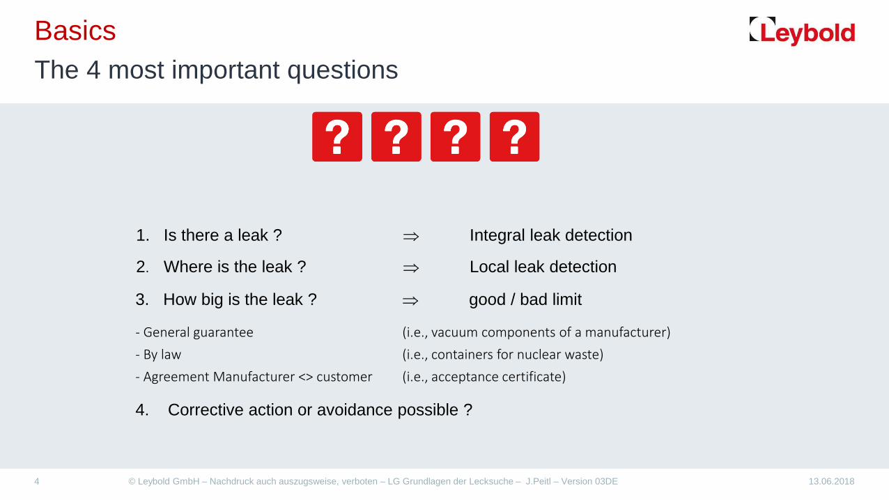
Basics The 4 most important questions
4. Corrective action or avoidance possible ?
1. Is there a leak ? ⇒ Integral leak detection
2. Where is the leak ? ⇒ Local leak detection
3. How big is the leak ? ⇒ good / bad limit
- General guarantee (i.e., vacuum components of a manufacturer) - By law (i.e., containers for nuclear waste) - Agreement Manufacturer <> customer (i.e., acceptance certificate)

13.06.2018 © Leybold GmbH – Nachdruck auch auszugsweise, verboten – LG Grundlagen der Lecksuche – J.Peitl – Version 03DE 5
General terms of vacuum technology Formular Collection - Summary
Definition Formular Unit
𝑮𝑮𝑮𝑮𝑮𝑮 𝑮𝑮𝒂𝒂𝒂𝒂𝒂𝒂𝒂𝒂𝒂𝒂 = 𝑷𝑷𝑷𝑷𝑷𝑷𝑮𝑮𝑮𝑮𝒂𝒂𝑷𝑷𝑷𝑷 ∙ 𝑽𝑽𝒂𝒂𝑽𝑽𝒂𝒂𝒂𝒂𝑷𝑷
𝑸𝑸 =∆𝒑𝒑 ∙ 𝑽𝑽∆𝒂𝒂 𝑮𝑮𝑮𝑮𝑮𝑮 𝒇𝒇𝑽𝑽𝒂𝒂𝒇𝒇 =
𝑪𝑪𝑪𝑪𝑮𝑮𝒂𝒂𝑪𝑪𝑷𝑷 𝒂𝒂𝒇𝒇 𝑪𝑪𝑮𝑮𝑮𝑮 𝑮𝑮𝒂𝒂𝒂𝒂𝒂𝒂𝒂𝒂𝒂𝒂𝒃𝒃𝒃𝒃 𝒂𝒂𝒕𝒕𝒂𝒂𝑷𝑷
𝑺𝑺 =𝑸𝑸𝒑𝒑 𝑷𝑷𝒂𝒂𝒂𝒂𝒑𝒑𝒕𝒕𝒂𝒂𝑪𝑪 𝑮𝑮𝒑𝒑𝑷𝑷𝑷𝑷𝒔𝒔 =
𝑮𝑮𝑮𝑮𝑮𝑮 𝒇𝒇𝑽𝑽𝒂𝒂𝒇𝒇𝑰𝑰𝒂𝒂𝒂𝒂𝑮𝑮𝑰𝑰𝑷𝑷 𝒑𝒑𝑷𝑷𝑷𝑷𝑮𝑮𝑮𝑮𝒂𝒂𝑷𝑷𝑷𝑷
= 𝒑𝒑 ∙ 𝑽𝑽 𝒂𝒂𝒃𝒃𝑮𝑮𝑷𝑷 ∙ 𝑽𝑽
𝒂𝒂𝒃𝒃𝑮𝑮𝑷𝑷 ∙ 𝑽𝑽
𝑮𝑮
𝑽𝑽𝑮𝑮
𝑷𝑷𝑷𝑷𝑷𝑷𝑮𝑮𝑮𝑮𝒂𝒂𝑷𝑷𝑷𝑷 =𝑭𝑭𝒂𝒂𝑷𝑷𝑭𝑭𝑷𝑷𝑨𝑨𝑷𝑷𝑷𝑷𝑮𝑮
𝒑𝒑 =𝑭𝑭𝑵𝑵𝑨𝑨
𝒂𝒂𝒃𝒃𝑮𝑮𝑷𝑷 𝑵𝑵𝒂𝒂𝒎
𝒂𝒂𝒎𝑪𝑪

13.06.2018 © Leybold GmbH – Nachdruck auch auszugsweise, verboten – LG Grundlagen der Lecksuche – J.Peitl – Version 03DE 6
General terms of vacuum technology Conductance
The conductance of an opening in a thin wall or of a line or of a line section between two defined cross sections is the ratio between gas throughput and the difference of the pressures which prevail to both sides of the opening or the line or the line section whereby a temperature equilibrium is assumed in the system (DIN 28 400):
C = Conductance [l/s] Q = Gas throughput [mbar·l/s] ∆p = Pressure difference [mbar] Generally, the conductance is not a constant. The magnitude of the conductance will basically depend within which pressure range the gas flow takes place.
Gas throughput Q C = —————————— = —
Pressure difference ∆p

13.06.2018 © Leybold GmbH – Nachdruck auch auszugsweise, verboten – LG Grundlagen der Lecksuche – J.Peitl – Version 03DE 7
General terms of vacuum technology Conductance - Effective Pumping Speed
S eff
S pump p pump
C pipe
Oven
p Oven
All fixtures between intake of pump system and oven will have the effect of reduction of pumping speed
Equation of continuity
poven ·Seff = qoven = qpump = ppump · Spump
The effect of reduction of intake piping will be described with conductance C
1 / Seff = 1 / Spump + 1 / Cpipe
Effective pumping speed available at the end of the piping
A piping should always as short as possible with possibly the biggest sensfull diameter
Total conductance of piping:
1 / L = 1 / C1 + 1 / C2 + 1 / C3 + 1 / Cn (l · s-1)

13.06.2018 © Leybold GmbH – Nachdruck auch auszugsweise, verboten – LG Grundlagen der Lecksuche – J.Peitl – Version 03DE 8
General terms of vacuum technology Pressure ranges used in vacuum technology and their characteristics
Rough vacuum Medium vacuum High vacuum Ultrahigh vacuum
Pressure p (mbar) 1013 – 1 1 – 10-3 10-3 – 10-7 < 10-7
Particle number density n (cm–3) 1019 – 1016 1016 – 1013 1013 – 109 < 109
Mean free path λ (cm) < 0,01 0,01 – 10 10 – 100000 > 100000
Possible Velocity Maximum the velocity of sound maximum for vacuum 100 m/s
Maximum thermal velocity, gas type depending
Impingement rate ZA (cm–2·s–1) 1023 – 1020 1020 – 1017 1017 – 1013 < 1013
Vol.- related collision rate ZV (cm–3 · s–1)
1029 – 1023 1023 – 1017 1017 – 1009 < 1009
Monolayer time t (s) < 10-5 10-5 – 10-2 10-2 – 100 > 100
Type of gas flow Knudsen number K = λ / d
Viscous flow K < 0,01
Knudsen flow K = 1
Molecular flow K > 100
Reynolds number Re Turbulent Re > 4000
Laminar Re < 2300
Other special features Convection depend on pressure Thermal conductivity depend on pressure
Volume collision rate is strong reduced
Particles on surfaces dominate in relation to particles in gaseous space
(numbers rounded off to whole power of ten)

13.06.2018 © Leybold GmbH – Nachdruck auch auszugsweise, verboten – LG Grundlagen der Lecksuche – J.Peitl – Version 03DE 9
Definition of leak and leak rate Gas flows inside a vacuum chamber
Not every gas flow is caused by a real leak!

13.06.2018 © Leybold GmbH – Nachdruck auch auszugsweise, verboten – LG Grundlagen der Lecksuche – J.Peitl – Version 03DE 10
Definition of leak and leak rate What is a leak ?
A leak is an hole in a wall or barrier, through which solids, liquids or gases can enter or exit undesirably in order to compensate an existing pressure difference.
Pressure pB Pressure pA
Leak qL
pB > pA
Wall

13.06.2018 © Leybold GmbH – Nachdruck auch auszugsweise, verboten – LG Grundlagen der Lecksuche – J.Peitl – Version 03DE 11
Definition of leak and leak rate What is a Leak according standards ?
According DIN EN 1330-8 a leak in NDT technology is defined as following:
Hole, porosity, permeable or other structure in the wall of an object capable of passing gas from one side of the wall to the other by the effect of pressure or concentration difference across the wall.

13.06.2018 © Leybold GmbH – Nachdruck auch auszugsweise, verboten – LG Grundlagen der Lecksuche – J.Peitl – Version 03DE 12
Definition of leak and leak rate Description of leak rates
Pressure rise / drop measurement
For the quantitative description of a leak, the term "leak rate" is used.
Leak rate qL = Gas-flow which passes through a leak under specific conditions
𝑳𝑳𝑷𝑷𝑮𝑮𝑰𝑰 𝑷𝑷𝑮𝑮𝒂𝒂𝑷𝑷 𝒒𝒒𝑳𝑳 =∆𝒑𝒑 ∙ 𝑽𝑽∆𝒂𝒂
𝒂𝒂𝒃𝒃𝑮𝑮𝑷𝑷 ∙ 𝑽𝑽𝑮𝑮
𝑳𝑳𝑷𝑷𝑮𝑮𝑰𝑰 𝑷𝑷𝑮𝑮𝒂𝒂𝑷𝑷 𝒒𝒒𝑳𝑳 =𝒂𝒂𝒂𝒂 𝑮𝑮𝑷𝑷𝑮𝑮𝒂𝒂𝒂𝒂
𝒀𝒀𝑷𝑷𝑮𝑮𝑷𝑷
Mass loss (T = standard, gas type specified)
Volume loss (p = constant)
𝑳𝑳𝑷𝑷𝑮𝑮𝑰𝑰 𝑷𝑷𝑮𝑮𝒂𝒂𝑷𝑷 𝒒𝒒𝑳𝑳 =𝑽𝑽𝒂𝒂
𝑽𝑽𝑮𝑮
𝑪𝑪𝑮𝑮
𝑳𝑳𝒕𝒕𝒂𝒂𝑷𝑷𝑷𝑷𝑺𝑺𝑷𝑷𝑭𝑭𝒂𝒂𝒂𝒂𝒔𝒔

13.06.2018 © Leybold GmbH – Nachdruck auch auszugsweise, verboten – LG Grundlagen der Lecksuche – J.Peitl – Version 03DE 13
Leakrate as a function of diameter of hole
Calculation: Pressure difference : ∆p = 1013 mbar
Diameter of hole : d = 1 cm
Velocity of gas = Velocity of sound = 330 m s-1
Volume / Second: 330 m/s · d2 π/4 = 25,92 · 103 cm3 · s-1 = 25,92 l/s
Quantity /Second: 1013 mbar · 25,92 l/s = 2,63 · 104 ≈104 mbar I/s
Diameter Equals Helium leak rate of (mbar I/s)
10-2 m = 1.0 cm 10 4
10-3 m = 1.0 mm 10 2
10-4 m = 0.1 mm 10 0 = 1!
10-5 m = 0.01 mm 10-2
10-6 m = 1.0 µm 10-4
10-7 m = 0.1 µm 10-6
10-8 m = 0.01 µm 10-8
10-9 m = 1.0 nm 10-10
10-10 m = 1.0 Angström 10-12

13 June 2018 © Leybold GmbH – Proprietary and Confidential - Leak detection technology - VA Version 02EN 14
Definition of leak and leak rate Estimation of leak size
Conclusion 1. Absolute tight is impossible, we have extreme low leak rates only 2. Not each leakage is a leak (faulty place) (Permeation at solid body is seldom, but a special problem of
elastomer sealing's)
Tight is: If the diameter of the molecule or atom is bigger then the lattice constant of the used material!
Examples for diameter of molecules or atoms
Helium He 1.90 · 10-10 m Hydrogen H2 2.40 · 10-10 m Argon Ar 2.88 · 10-10 m Nitrogen N2 3.15 · 10-10 m Water H2O 6.00 · 10-10 m Oxygen O2 9.00 · 10-10 m
Examples for lattice constants
NaCl 5.60 · 10-10 m Glass ≈ 5.0 · 10-10 m Aluminium oxide 5.10 · 10-10 m

1) Gas concentration C = (100%) 99.9% 2) Pressure difference inside and outside ∆ p = 1013 mbar 3) Temperature T = 0 °C = 273 K 4) No partial flow leak detection Why? From the common gas equation we know temperature change and pressure change will influence each other and my cause a change of the shown leak rate.
p = pressure of gas [mbar] V = volume [l] m = Mass of a gas [g] M = molar Mass of a gas [g/mol] T = absolute temperature of Gas [K] T [K] = 273,15 + θ [°C] R = molar gas constant = 83,145 mbar · l · mol-1 · K-1
13 June 2018 © Leybold GmbH – Proprietary and Confidential - Leak detection technology - VA Version 02EN 15
Definition of leak and leak rate Standard conditions for to determine Leak rates qN
𝒑𝒑 ∙ 𝑽𝑽 =𝒂𝒂𝑴𝑴 ∙ 𝑹𝑹 ∙ 𝑻𝑻

13 June 2018 © Leybold GmbH – Proprietary and Confidential - Leak detection technology - VA Version 02EN 16
Definition of leak and leak rate Understanding of tightness
Understanding
Leak rate range
Particle size Remarks For Helium mbar l/s For air at 20°C
kg/h
Water tight 10-2 10-5 Drop
Vapor tight 10-3 10-6 Sweat
Bacteria tight 10-4 10-7 D ~ 10-6 m
Fuel and oil tight 10-5 10-8
Virus tight 10-6 10-9 D ~ 0.3x10⁻⁶ m
Gas tight 10-7 10-10
„Absolute tight" 10-10 10-11 Technical tight (better)
13 June 2018 © Leybold GmbH – Proprietary and Confidential - Leak detection technology - VA Version 02EN 17
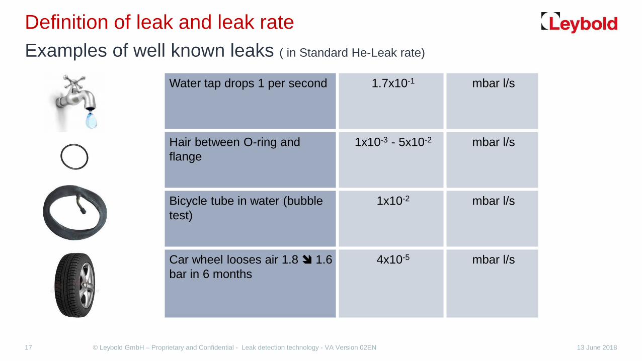
Definition of leak and leak rate Examples of well known leaks ( in Standard He-Leak rate)
Water tap drops 1 per second 1.7x10⁻¹ mbar l/s
Hair between O-ring and flange
1x10⁻³ - 5x10⁻² mbar l/s
Bicycle tube in water (bubble test)
1x10⁻² mbar l/s
Car wheel looses air 1.8 1.6 bar in 6 months
4x10⁻⁵ mbar l/s

13.06.2018 © Leybold GmbH – Nachdruck auch auszugsweise, verboten – LG Grundlagen der Lecksuche – J.Peitl – Version 03DE 18
Definition of leak and leak rate Examples for leaks
Depending on the nature of failures occurring, the following types of leak are vary in:
Leaks in detachable connections:
Flanges, grindings
Leaks in permanent connections:
Soldering and welding seams / spots, glue Joints
Virtual leaks: In vacuum systems, gases - or evaporating liquids - are released from internal cavities in castings, from gaps and blind holes or from plastics
Caution: - Welding seams should be internal if possible (to prevent gaps)
- Drill screws or slot the screw thread before using screws in blind holes

Permeation leaks: If two different gas chambers are separated by a solid wall and with different pressures from each other, gas flows from the gas chamber with the higher pressure through the solid body into the gas chamber with the lower pressure.
Cold and warm leaks: open after extreme temperature stress, especially at soldering and welding seams / points
Pore-leaks: typically after mechanical deformation or heat treatment of polycrystalline materials or castings
In-direct leaks: Untightened feed lines in vacuum systems (water, compressed air, etc.)
Serial leaks: The leak is at the end of several "series connected rooms".
13.06.2018 © Leybold GmbH – Nachdruck auch auszugsweise, verboten – LG Grundlagen der Lecksuche – J.Peitl – Version 03DE 19
Definition of leak and leak rate Examples for leaks

13.06.2018 © Leybold GmbH – Nachdruck auch auszugsweise, verboten – LG Grundlagen der Lecksuche – J.Peitl – Version 03DE 20
Methods of leak detection Comparison
Smallest detectable leak rate
Leak detection-Method
Helium-Standard-Leak rate test gas: Helium 4 ∆p = 1000 mbar QN
R 134a Test medium
Method technology Quantitative leak detection
method
mbar*l/s g/year
Helium- Leak detector 1,0E-12 Helium 4 vacuum Yes
Halogen- Leak detector 1,0E-06 0,13 Halogenated substances Overpressure / vacuum Yes
Sniff- Leak detector 1,0E-06 0,13 Refrigerant, helium 4 and
other gases Overpressure Yes
Foaming agent 1,0E-04 0,70 Air & others Overpressure No
Thermal conductivity 1,0E-04 0,70 No air but others Overpressure / vacuum No
Pressure drop test 1,0E-04 0,70 Air & others Overpressure Yes
Pressure rise test 1,0E-04 0,70 Air & others vacuum Yes
Bubble Test 1,0E-03 7,00 Air & others Overpressure No (yes)
Water- pressure test 1,0E-03 7,00 Water Overpressure No

13.06.2018 © Leybold GmbH – Nachdruck auch auszugsweise, verboten – LG Grundlagen der Lecksuche – J.Peitl – Version 03DE 21
Methods of leak detection Principle methods of Pressure change method Group D according DIN EN 1779
Pressure drop test D1 Integral leak testing (test gas flow out of object)
test gas: e.g. Air, Nitrogen
Pressure rise test D2 Integral leak testing (test gas flow into object)
test gas: Air

13.06.2018 © Leybold GmbH – Nachdruck auch auszugsweise, verboten – LG Grundlagen der Lecksuche – J.Peitl – Version 03DE 22
Methods of leak detection Example, the pressure rise method
How long does it take for the pressure in a 1 liter chamber to rise from 1 to 2 mbar when the leak is 1x10⁻⁶ mbar l/s ?
𝒒𝒒𝑳𝑳 =∆𝒑𝒑 ∙ 𝑽𝑽𝒂𝒂
𝒂𝒂 =∆𝒑𝒑 ∙ 𝑽𝑽𝒒𝒒𝑳𝑳
𝒂𝒂 =𝟏𝟏𝒂𝒂𝒃𝒃𝑮𝑮𝑷𝑷 ∙ 𝟏𝟏𝑽𝑽𝒕𝒕𝒂𝒂𝑷𝑷𝑷𝑷𝟏𝟏 ∙ 𝟏𝟏𝟏𝟏−𝟔𝟔𝒂𝒂𝒃𝒃𝑮𝑮𝑷𝑷 𝑽𝑽 /𝑮𝑮 = 𝟏𝟏.𝟏𝟏𝟏𝟏𝟏𝟏.𝟏𝟏𝟏𝟏𝟏𝟏𝑮𝑮 = 𝟐𝟐𝟐𝟐𝟐𝟐,𝟐𝟐𝑪𝑪 = 𝟏𝟏𝟏𝟏,𝟓𝟓 𝒔𝒔𝑮𝑮𝒃𝒃𝑮𝑮
volume chamber V = 1 liter
leak qL = 1x10⁻⁶ mbar l/s
pressure change ∆𝒑𝒑 = 1 mbar > 2 mbar
vacuum
atmosphere

13/06/2018 © Leybold GmbH – Nachdruck auch auszugsweise, verboten – LG Grundlagen der Lecksuche – J.Peitl – Version 03DE 23
Methods of leak detection Pressure rise effects on a vacuum tank
a) Leak rate
b) Desorption
c) Leak rate + desorption
time

13.06.2018 © Leybold GmbH – Nachdruck auch auszugsweise, verboten – LG Grundlagen der Lecksuche – J.Peitl – Version 03DE 24
Methods of leak detection Example, the pressure drop technique (1)
Given data:
Leak in the tire qL = 1 mbar · l · s-1 Pressure in the tire p = 2 bar (2000 mbar) Min operating pressure pmin = 1,3 bar (1300 mbar) tire volume V = 20 l How long can be driven with the tire until the minimum operating pressure is reached?
𝒂𝒂 =∆𝒑𝒑 ∙ 𝑽𝑽𝒒𝒒𝑳𝑳
𝒂𝒂 =𝟐𝟐𝟏𝟏𝟏𝟏 𝒂𝒂𝒃𝒃𝑮𝑮𝑷𝑷 ∙ 𝟐𝟐𝟏𝟏 𝑽𝑽𝒕𝒕𝒂𝒂𝑷𝑷𝑷𝑷
𝟏𝟏 𝒂𝒂𝒃𝒃𝑮𝑮𝑷𝑷 𝑽𝑽 /𝑮𝑮 = 𝟏𝟏𝟏𝟏.𝟏𝟏𝟏𝟏𝟏𝟏 𝑮𝑮 = 𝟑𝟑,𝟖𝟖𝟖𝟖 𝑪𝑪 ≈ 𝟏𝟏 𝑪𝑪𝒂𝒂𝒂𝒂𝑷𝑷𝑮𝑮
After about 4 hours, the tire can slip from the rim!

13.06.2018 © Leybold GmbH – Nachdruck auch auszugsweise, verboten – LG Grundlagen der Lecksuche – J.Peitl – Version 03DE 25
Methods of leak detection Example, the pressure drop technique (2)
task:
The tyre pressure should be sufficient for at least half a year. (6 months = 1,58 · 107 s)
What is the leak rate q?
> the leak is here already factor 1000 smaller!
If the required time is 1 year, the leak rate will be : qmax = 4,4 · 10-4 mbar l/s Detection limit, means smallest visible leak rate in the water bath (bubble test) ~ 1· 10-4 mbar · l /s
𝒒𝒒 =∆𝒑𝒑 ∙ 𝑽𝑽𝒂𝒂
𝒂𝒂 =𝟐𝟐𝟏𝟏𝟏𝟏 𝒂𝒂𝒃𝒃𝑮𝑮𝑷𝑷 ∙ 𝟐𝟐𝟏𝟏 𝑽𝑽𝒕𝒕𝒂𝒂𝑷𝑷𝑷𝑷
𝟏𝟏,𝟓𝟓𝟖𝟖 ∙ 𝟏𝟏𝟏𝟏𝟐𝟐𝑮𝑮 = 𝟖𝟖,𝟖𝟖𝟔𝟔 ∙ 𝟏𝟏𝟏𝟏−𝟏𝟏𝒂𝒂𝒃𝒃𝑮𝑮𝑷𝑷 𝑽𝑽/𝑮𝑮 ≈ 𝟏𝟏 ∙ 𝟏𝟏𝟏𝟏−𝟑𝟑𝒂𝒂𝒃𝒃𝑮𝑮𝑷𝑷 𝑽𝑽/𝑮𝑮

13.06.2018 © Leybold GmbH – Nachdruck auch auszugsweise, verboten – LG Grundlagen der Lecksuche – J.Peitl – Version 03DE 26
Methods of leak detection Principle methods of tracer gas groups A and B according DIN EN 1779
Tracer gas with Vacuum Technique Group A (Helium from outside) Integral leak testing A1 (Helium from outside)
Local leak detection A3 (Helium spay from outside)
Tracer gas: Helium
Tracer gas with Overpressure Group B Integral leak detection ( He inside B6)
Local leak detection ( sniffing B4)
Tracer gas: e.g. Helium, Halogens, Ammonia

13.06.2018 © Leybold GmbH – Nachdruck auch auszugsweise, verboten – LG Grundlagen der Lecksuche – J.Peitl – Version 03DE 27
Methods of leak detection Vacuum Method Procedure A1 Integral leak detection
Heliu
m
Chamber with Tracer gas
Test body (evacuated)
Leak detector Tracer gas Helium
Lowest detectable leak rate < 5x10-12 mbar l/s

13.06.2018 © Leybold GmbH – Nachdruck auch auszugsweise, verboten – LG Grundlagen der Lecksuche – J.Peitl – Version 03DE 28
Methods of leak detection Vacuum Method Procedure A3 Local leak detection
Heliu
m
Spray gun
Test body (evacuated)
Leak detector Tracer gas Helium
Lowest detectable leak rate < 5x10-12 mbar l/s

13.06.2018 © Leybold GmbH – Nachdruck auch auszugsweise, verboten – LG Grundlagen der Lecksuche – J.Peitl – Version 03DE 29
Methods of leak detection Overpressure Method Procedure B6 Integral leak detection
Heliu
m
Chamber (evacuated)
Test body with tracer gas
Leak detector Tracer gas Helium
Lowest detectable leak rate < 5x10⁻¹⁰ mbar l/s

13.06.2018 © Leybold GmbH – Nachdruck auch auszugsweise, verboten – LG Grundlagen der Lecksuche – J.Peitl – Version 03DE 30
Methods of leak detection Overpressure Method Procedure B4 Local leak detection (sniffing)
Heliu
m Test body with
tracer gas
Leak detector Tracer gas Helium
Lowest detectable leak rate < 5x10⁻⁷ mbar l/s
Sniffer tip

13 June 2018 © Leybold GmbH – Proprietary and Confidential - Leak detection technology - VA Version 02EN 31
The Helium Leak Detector Phoenix L 300 i

13.06.2018 © Leybold GmbH – Nachdruck auch auszugsweise, verboten – LG Grundlagen der Lecksuche – J.Peitl – Version 03DE 32
The Helium Leak Detector Helium as Test gas
Helium is an ideal test gas for the leak detection. Its positive features are: Excellent separation within a mass spectrometer from neighboring masses Only 5 ppm are contained in the air, i.e., a very low background Smallest gas particle except hydrogen Inert, i.e., does not react with other substances Environmentally friendly: non-toxic, non-combustible, non-explosive Non-condensable within the entire range of technical applications Lighter than air, i.e., it aids leak testing, as the test gas may escape upwards
Source: Wikipedia
Gas Chemisches Symbol
Molare Masse: M
Viskosität bei 25ºC: h (25°C)
g · mol-1 10-6 · Pa · s = µ Pa · sHelium He 4 19,68

13.06.2018 © Leybold GmbH – Nachdruck auch auszugsweise, verboten – LG Grundlagen der Lecksuche – J.Peitl – Version 03DE 33
The Helium Leak Detector What does a helium leak detector measure?
•A Helium leak detector measures the helium partial pressure in the pump line and converts it into a leak rate. Sensor for
helium partial pressure pHe
Vacuum pump system with pumping speed
S(pHe)
𝒒𝒒𝑳𝑳 = 𝒑𝒑 𝑯𝑯𝑷𝑷 ∙ 𝑺𝑺(𝒑𝒑 𝑯𝑯𝑷𝑷)

13.06.2018 © Leybold GmbH – Nachdruck auch auszugsweise, verboten – LG Grundlagen der Lecksuche – J.Peitl – Version 03DE 34
The Helium Leak Detector Main flow - and Counter flow – Leak detector
High vacuum pump
High vacuum pump
Fore vacuum pump Fore vacuum pump auxiliary pump
auxiliary pump
He He

13.06.2018 © Leybold GmbH – Nachdruck auch auszugsweise, verboten – LG Grundlagen der Lecksuche – J.Peitl – Version 03DE 35
The Helium Leak Detector Selective Mass spectrometer, 180° Sector field MS

13.06.2018 © Leybold GmbH – Nachdruck auch auszugsweise, verboten – LG Grundlagen der Lecksuche – J.Peitl – Version 03DE 36
The Helium Leak Detector Vacuum Diagram of a Counter-flow Leak Detector
Mass- spectrometer
Turbo- Molecular pump
Fore vacuum pump
Exhaust
Vent valve
Test connection
2
Gas ballast
13.06.2018 © Leybold GmbH – Nachdruck auch auszugsweise, verboten – LG Grundlagen der Lecksuche – J.Peitl – Version 03DE 37
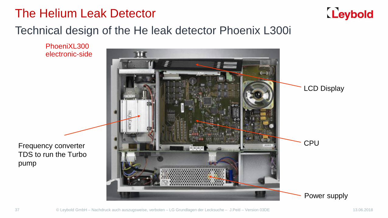
The Helium Leak Detector Technical design of the He leak detector Phoenix L300i
Frequency converter TDS to run the Turbo pump
Power supply
LCD Display
CPU
PhoeniXL300 electronic-side

13.06.2018 © Leybold GmbH – Nachdruck auch auszugsweise, verboten – LG Grundlagen der Lecksuche – J.Peitl – Version 03DE 38
The Helium Leak Detector Technical design of the He leak detector Phoenix L300i
TRIVAC 2.5 E
Exhaust-Filter
TURBOVAC TW 70 LS
Intake-Valve-Block
180°-Selective Mass Spectrometer
Ion - detector
Interfaces:
SPS
Remote
RS 232
Intake DN 25 KF
PhoeniXL300 vacuum side
13.06.2018 © Leybold GmbH – Nachdruck auch auszugsweise, verboten – LG Grundlagen der Lecksuche – J.Peitl – Version 03DE 39
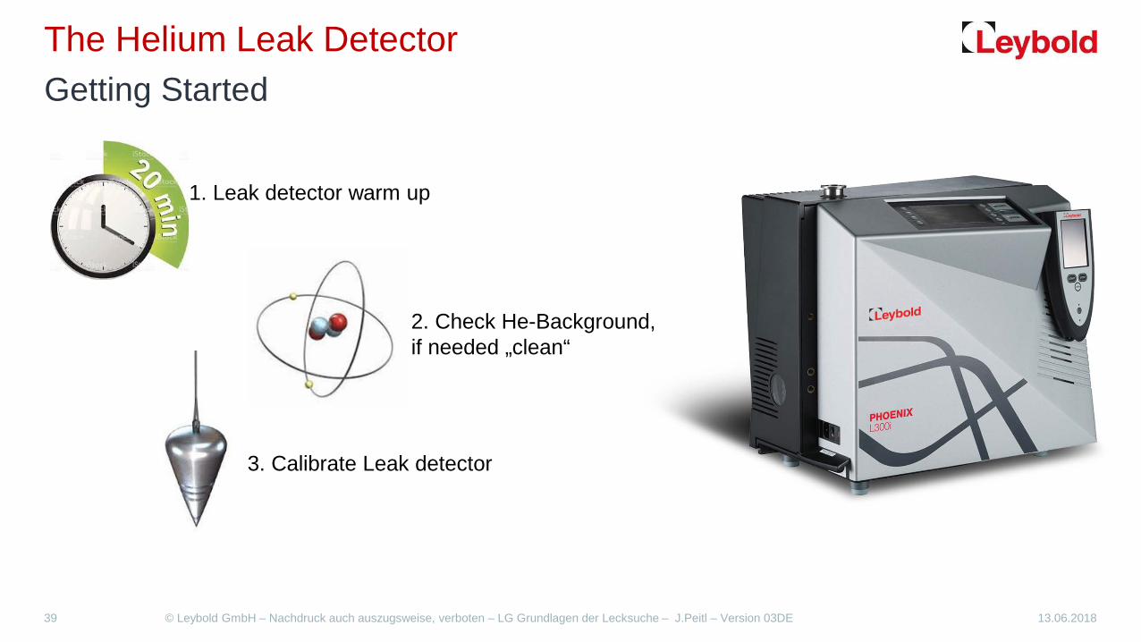
The Helium Leak Detector Getting Started
1. Leak detector warm up
2. Check He-Background, if needed „clean“
3. Calibrate Leak detector

13.06.2018 © Leybold GmbH – Nachdruck auch auszugsweise, verboten – LG Grundlagen der Lecksuche – J.Peitl – Version 03DE 40
The Helium Leak Detector Display Example
Main menu Trend mode
Bar mode Vacuum Scheme

13.06.2018 © Leybold GmbH – Nachdruck auch auszugsweise, verboten – LG Grundlagen der Lecksuche – J.Peitl – Version 03DE 41
The Helium Leak Detector Technical design of the He leak detector Phoenix L300i
Intake
Exhaust
TMP
MS: He Mass spectrometer
TMP+Trivac: Pumps evacuate MS and Test specimen
p1+p2: Control Gauges Inlet and backing pressure
V1 Pump down valve
V2a Backing valve TMP
V2b Inlet valve operation Gross mode
V3 Venting valve
V4 Inlet valve operation Fine mode
V5 TMP venting valve
V6 Gas ballast valve
V7 Test leak valve

13.06.2018 © Leybold GmbH – Nachdruck auch auszugsweise, verboten – LG Grundlagen der Lecksuche – J.Peitl – Version 03DE 42
The Helium Leak Detector Technical design of the He leak detector Phoenix L300i
Measure-Method: Vacuum(-Technique) Measure-Modus: „No Measure-Modus“ Intake pressure: p1 > 15 mbar Start evacuation

13.06.2018 © Leybold GmbH – Nachdruck auch auszugsweise, verboten – LG Grundlagen der Lecksuche – J.Peitl – Version 03DE 43
The Helium Leak Detector Technical design of the He leak detector Phoenix L300i
Measure-Method: Vacuum(-Technique) Measure-Modus: „GROSS“ Intake pressure: 0,1 mbar < p1 < 15 mbar Lowest detectable He4-Leak rate: 1·10-8 mbar·l/s

13.06.2018 © Leybold GmbH – Nachdruck auch auszugsweise, verboten – LG Grundlagen der Lecksuche – J.Peitl – Version 03DE 44
The Helium Leak Detector Technical design of the He leak detector Phoenix L300i
Measure-Method: Vacuum(-Technique) Measure-Modus: „FINE“ Intake pressure: p1 < 0,1 mbar Lowest detectable He4-Leak rate: 1·10-12 mbar·l/s

13.06.2018 © Leybold GmbH – Nachdruck auch auszugsweise, verboten – LG Grundlagen der Lecksuche – J.Peitl – Version 03DE 45
The Helium Leak Detector Vacuum schematics of the Phoenix L 300 family
Phoenix L300 i Phoenix L300 i Dry Phoenix L300 i Modul
GROSS
FINE
GROSS
FINE
GROSS
FINE
Diaphragm Pump External Pump rotary vane
pump or scroll pump
Trivac 2.5 E

13.06.2018 © Leybold GmbH – Nachdruck auch auszugsweise, verboten – LG Grundlagen der Lecksuche – J.Peitl – Version 03DE 46
The Helium Leak Detector Technical Data
Phoenix L300 i Phoeniv L300 i Dry Phoenix L300 i Modul
Lowest detectable He leak rate (vacuum mode) mbarl/s <5x10-12 <3x10-11 <5x10-12/<8x10-12
Lowest detectable leak rate (sniffer mode) mbarl/s <1x10⁻⁷ <1x10⁻⁷ <1x10⁻⁸
Max. detectable He leak rate (vacuum mode) mbarl/s > 0,1 > 0,1 > 0,1 Max. permissible inlet pressure mbar 15 15 15 Max. permissible inlet pressure w partial flow set mbar 1000 - - Pumping speed during pump down m3/h 2,5 (50 Hz)
3 (60 Hz) 1,6 (50 Hz) 1,8 (60 Hz)
16/20 (50/60 Hz) D16B 25/30 (50/60 Hz) D25B 30/36 (50/60 Hz) Scroll
Pumping speed for Helium l/s > 2,5 > 2,5 > 2,5 Pumping speed with partial flow set and D16B l/s 4,4 (50Hz) Pumping speed with partial flow set and D25B l/s 7 (50 Hz) Time constant for leak rate signal S < 1 < 1 < 1 Time until ready for operation min < 2 < 2 < 2 Mass spectrometer 180° magn. Sector field Detectable masses 4He; 3He; H2 amu 4; 3 ; 2 4; 3 ; 2 4; 3 ; 2 Power consumption 420 VA 350 VA 350 VA Weight kg 40 37,5 29

13.06.2018 © Leybold GmbH – Nachdruck auch auszugsweise, verboten – LG Grundlagen der Lecksuche – J.Peitl – Version 03DE 47
Calibration - and test leaks Definition Calibration
Calibration in measurement technology is a measurement process for reliably reproducible detection and documentation of the deviation of a measuring device (here leak detector) from a reference leak (test leak). The calibration includes a second step, namely the consideration of the deviation during the subsequent use of the measuring device for correcting the readings. The PhoniXL300i automatically performs this correction with the determined "calibration factor".

13.06.2018 © Leybold GmbH – Nachdruck auch auszugsweise, verboten – LG Grundlagen der Lecksuche – J.Peitl – Version 03DE 48
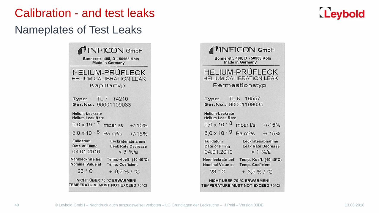
Calibration - and test leaks Definition Test Leak
The test leak is a device which emits a precisely known helium gas stream. There are two basic types:
Permeation test leak:
Long time stability
Large temp. coefficient (3.5% / °C)
Recommendable only with a gas tank
Capillary test leak:
Small temp. coefficient (0,3% / °C)
Short response time
Clog easily
13.06.2018 © Leybold GmbH – Nachdruck auch auszugsweise, verboten – LG Grundlagen der Lecksuche – J.Peitl – Version 03DE 49
Calibration - and test leaks Nameplates of Test Leaks

13.06.2018 © Leybold GmbH – Nachdruck auch auszugsweise, verboten – LG Grundlagen der Lecksuche – J.Peitl – Version 03DE 50
Calibration - and test leaks Overview for Test leaks
TL 4/TL 6: Capillary test leak without Gas support TL 4-6: Capillary test leak for sniffer and vacuum use TL 7: (internal) Capillary test leak TL 5: Capillary test leak for use in vacuum TL 8/TL 9: Permeation- (Diffusion-) test leak

13.06.2018 © Leybold GmbH – Nachdruck auch auszugsweise, verboten – LG Grundlagen der Lecksuche – J.Peitl – Version 03DE 51
The Helium Background He-Background vs. He-Leak rate
5 ppm of Air flow is Helium
99.9 % of flow is Helium

13.06.2018 © Leybold GmbH – Nachdruck auch auszugsweise, verboten – LG Grundlagen der Lecksuche – J.Peitl – Version 03DE 52
The Helium Background Display – Background - Detection Limit
5ppm of the air leakage flow is
helium. This is the
helium background of the test body.
Which helium background is to be expected?
𝒒𝒒𝑯𝑯𝑷𝑷 = 𝒒𝒒𝑨𝑨𝒕𝒕𝑷𝑷 ∙ 𝟓𝟓𝒑𝒑𝒑𝒑𝒂𝒂
𝒒𝒒𝑯𝑯𝑷𝑷 = 𝒑𝒑 ∙ 𝑺𝑺 ∙ 𝟓𝟓 ∙ 𝟏𝟏𝟏𝟏−𝟔𝟔
𝒒𝒒 = 𝒑𝒑 ∙ 𝑺𝑺
𝑨𝑨𝒕𝒕𝑷𝑷 𝑽𝑽𝑷𝑷𝑮𝑮𝑰𝑰𝑮𝑮𝑪𝑪𝑷𝑷 𝒒𝒒𝑮𝑮𝒕𝒕𝑷𝑷 =𝑯𝑯𝑷𝑷 − 𝑩𝑩𝑮𝑮𝑭𝑭𝑰𝑰𝑪𝑪𝑷𝑷𝒂𝒂𝒂𝒂𝒂𝒂𝒔𝒔 𝒒𝒒𝑯𝑯𝑷𝑷
𝟓𝟓 𝒑𝒑𝒑𝒑𝒂𝒂
𝑨𝑨𝒕𝒕𝑷𝑷 𝑽𝑽𝑷𝑷𝑮𝑮𝑰𝑰𝑮𝑮𝑪𝑪𝑷𝑷 𝒒𝒒𝑮𝑮𝒕𝒕𝑷𝑷 = 𝒒𝒒𝑯𝑯𝑷𝑷 ∙ 𝟐𝟐 ∙ 𝟏𝟏𝟏𝟏𝟓𝟓 𝒂𝒂𝒃𝒃𝑮𝑮𝑷𝑷 ∙ 𝑽𝑽/𝑮𝑮
What air leakage exists with given
Helium background?
P Intake pressure
S Pumping speed q Gas flow Air

13 June 2018 © Leybold GmbH – Proprietary and Confidential - Leak detection technology - VA Version 02EN 53
The Helium Background Terms / Examples
Leak and He from spraying Measured signal:
Permeation from sealing's at growing He background e.g. tubing from elastomer
Helium from the last test specially at big chambers or sealing's.
Background from Test object + tubing:
Helium at the (rotary vane-) pump oil Helium at dead volumes from diaphragm pumps or in Elastomer sealing's
Leak detector background:
(or Zero point shifting ) at digital displays maximum for 2 decades reasonable
Zero point suppression:
smallest selectable signal above the electrical noise (Pumps al compressor; Stability of the electrical signal)
Lowest detectable leak rate:
The Leak detector takes every back ground signal as a leak signal (and simply added). The reading is the Addition of He signal and He background (from Leak detector or test object).

13.06.2018 © Leybold GmbH – Nachdruck auch auszugsweise, verboten – LG Grundlagen der Lecksuche – J.Peitl – Version 03DE 54
The Helium Background Counteraction He background
Zero point suppression for better reading
He background of the detector is working with an automatic „dynamic Zero point suppression“ also applicable with manual use of 0- button
Gas ballast use for. 30 min
2 measurements are needed to indicate the right He leak rate.
1. background of the test object without spraying Helium
2. Helium Signal with 99.9 % Helium
3. Building the difference of Helium signal minus background signal
The He background should not be mixed up with the slowly decreasing He signal during switching the leak detector on the vacuum system.

13 June 2018 © Leybold GmbH – Proprietary and Confidential - Leak detection technology - VA Version 02EN 55
The Helium Background Zero point suppression
Warning
(suppressed) He background < 2·10-10 1· 10-8
1· 10-8
surpressed with ZERO <1· 10-10
Leak 2· 10-8 2· 10-8 2· 10-8
Display 2· 10-8 3· 10-8 2· 10-8

13.06.2018 © Leybold GmbH – Nachdruck auch auszugsweise, verboten – LG Grundlagen der Lecksuche – J.Peitl – Version 03DE 56
Partial flow operation Leak detector with Partial Flow Set
In partial flow operation, the test object is additionally evacuated by an auxiliary pump. A part of the gas flows through the auxiliary pump, a part to the leak detector. In sum, a higher pumping speed is available
Advantages:
- Faster measuring readiness
- Faster response time
- Fast flood of large test objects.
Gas flow
Partial flow valve
Auxiliary D25B
13.06.2018 © Leybold GmbH – Nachdruck auch auszugsweise, verboten – LG Grundlagen der Lecksuche – J.Peitl – Version 03DE 57
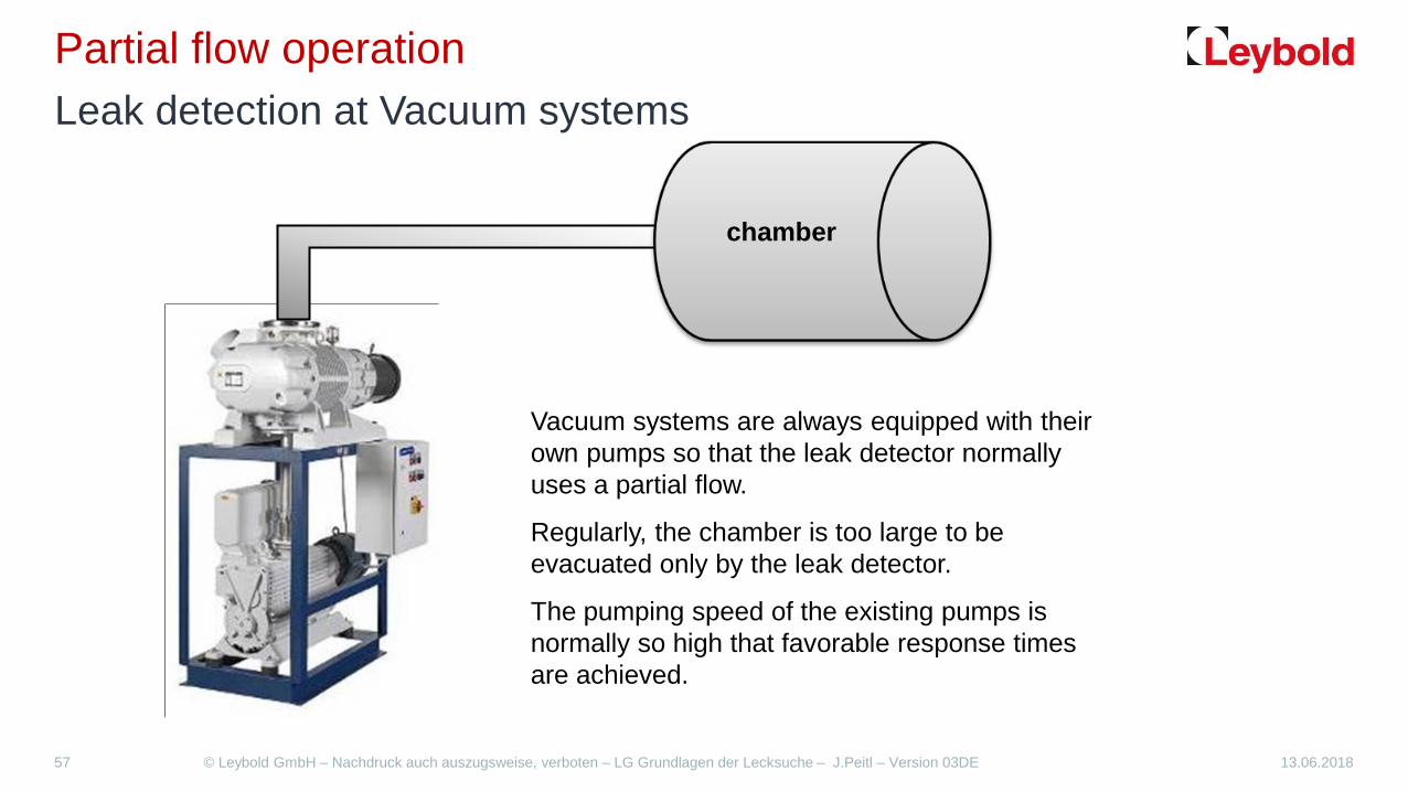
Partial flow operation Leak detection at Vacuum systems
Vacuum systems are always equipped with their own pumps so that the leak detector normally uses a partial flow.
Regularly, the chamber is too large to be evacuated only by the leak detector.
The pumping speed of the existing pumps is normally so high that favorable response times are achieved.
chamber

13.06.2018 © Leybold GmbH – Nachdruck auch auszugsweise, verboten – LG Grundlagen der Lecksuche – J.Peitl – Version 03DE 58
Partial flow operation 5 pre thoughts for partial flow leak detection at a vacuum system
Chamber
1. Where can I connect the leak detector mechanically ? 2. What is the pressure level at my connecting flange ? 3. What will be the partial flow factor ? 4. How long do I have to wait for the max. reading of leak
rate ? 5. Which level of He back ground has to be expected by
using partial flow leak detection ?

13.06.2018 © Leybold GmbH – Nachdruck auch auszugsweise, verboten – LG Grundlagen der Lecksuche – J.Peitl – Version 03DE 59
Partial flow operation Partial Flow System (1)
qoverall
qLD
qpump system
𝜸𝜸 = partial flow factor
qoverall = qLD + qpump system
𝜸𝜸 =𝒒𝒒𝑳𝑳𝑳𝑳
(𝒒𝒒 𝑳𝑳𝑳𝑳
+ 𝒒𝒒 𝑷𝑷𝒂𝒂𝒂𝒂𝒑𝒑 𝑮𝑮𝒃𝒃𝑮𝑮𝒂𝒂𝑷𝑷𝒂𝒂
)
Chamber

13.06.2018 © Leybold GmbH – Nachdruck auch auszugsweise, verboten – LG Grundlagen der Lecksuche – J.Peitl – Version 03DE 60
Partial flow operation Partial Flow System (2)
qoverall
qLD
qbacking pump 𝜸𝜸 = partial flow factor
qoverall = qLD + qbacking pump
𝜸𝜸 =𝒒𝒒𝑳𝑳𝑳𝑳
(𝒒𝒒 𝑳𝑳𝑳𝑳
+ 𝒒𝒒 𝒃𝒃𝑮𝑮𝑭𝑭𝑰𝑰𝒕𝒕𝒂𝒂𝑪𝑪 𝒑𝒑𝒂𝒂𝒂𝒂𝒑𝒑
)
Chamber

13.06.2018 © Leybold GmbH – Nachdruck auch auszugsweise, verboten – LG Grundlagen der Lecksuche – J.Peitl – Version 03DE 61
Partial flow operation Calculation of partial flow factor Example:
Q target = 5 x 10⁻⁴ mbar l/s
SLD= 2,5 l/s S backing pump= 69 l/s
𝜸𝜸 =𝑺𝑺𝑳𝑳𝑳𝑳
(𝑺𝑺 𝑳𝑳𝑳𝑳
+ 𝑺𝑺 𝒃𝒃𝑮𝑮𝑭𝑭𝑰𝑰𝒕𝒕𝒂𝒂𝑪𝑪 𝒑𝒑𝒂𝒂𝒂𝒂𝒑𝒑
)
Chamber
𝜸𝜸 =𝟐𝟐,𝟓𝟓 𝑽𝑽/𝑮𝑮
(𝟐𝟐,𝟓𝟓𝑽𝑽/𝑮𝑮 + 𝟔𝟔𝟔𝟔𝑽𝑽/𝑮𝑮) = 𝟏𝟏,𝟏𝟏𝟑𝟑𝟓𝟓
𝒒𝒒𝑳𝑳𝑳𝑳 = 𝜸𝜸 ∙ 𝒒𝒒 𝒂𝒂𝑮𝑮𝑷𝑷𝑪𝑪𝑷𝑷𝒂𝒂
= 𝟏𝟏,𝟏𝟏𝟑𝟑𝟓𝟓 ∙ 𝟓𝟓 ∙ 𝟏𝟏𝟏𝟏−𝟏𝟏
= 𝟏𝟏,𝟐𝟐 ∙ 𝟏𝟏𝟏𝟏−𝟓𝟓 𝒂𝒂𝒃𝒃𝑮𝑮𝑷𝑷 𝑽𝑽/𝑮𝑮
pressure

13.06.2018 © Leybold GmbH – Nachdruck auch auszugsweise, verboten – LG Grundlagen der Lecksuche – J.Peitl – Version 03DE 62
Partial flow operation Determination of partial flow factor with a test leak Example:
Q Test leak
= 3,5 x 10⁻⁵ mbar l/s
𝑷𝑷𝑮𝑮𝑷𝑷𝒂𝒂𝒕𝒕𝑮𝑮𝑽𝑽 𝒇𝒇𝑽𝑽𝒂𝒂𝒇𝒇 𝒇𝒇𝑮𝑮𝑭𝑭𝒂𝒂𝒂𝒂𝑷𝑷 𝜸𝜸 =𝑳𝑳𝒕𝒕𝑮𝑮𝒑𝒑𝑽𝑽𝑮𝑮𝒃𝒃𝑷𝑷𝒔𝒔 𝑽𝑽𝑷𝑷𝑮𝑮𝑰𝑰 𝑷𝑷𝑮𝑮𝒂𝒂𝑷𝑷
𝑻𝑻𝑷𝑷𝑮𝑮𝒂𝒂 𝑽𝑽𝑷𝑷𝑮𝑮𝑰𝑰
Chamber
𝜸𝜸 =𝟏𝟏 ∙ 𝟏𝟏𝟏𝟏−𝟔𝟔 𝒂𝒂𝒃𝒃𝑮𝑮𝑷𝑷 𝑽𝑽/𝑮𝑮𝟑𝟑,𝟓𝟓 ∙ 𝟏𝟏𝟏𝟏−𝟓𝟓𝒂𝒂𝒃𝒃𝑮𝑮𝑷𝑷 𝑽𝑽/𝑮𝑮)
= 𝟏𝟏,𝟏𝟏𝟐𝟐𝟖𝟖
Q display = 1 x 10⁻⁶ mbar l/s

13.06.2018 © Leybold GmbH – Nachdruck auch auszugsweise, verboten – LG Grundlagen der Lecksuche – J.Peitl – Version 03DE 64
Partial flow operation Connect leak detector to the pump system
C
B
A
Q
V1
V2
V3
D
Connection A (V1 closed) The leak detector can not evacuate the chamber sufficiently. The sensitivity is good, but the pressure and thus the Helium background remain high. The response time is too high. Connection A (V1 open) The pump system evacuates the chamber and reaches with a low end pressure also a low Helium background. The sensitivity is significantly reduced by the partial flow ratio. Connection B The pressure and He background are larger as compared to A. The sensitivity is improved by a more favorable partial flow ratio. Connection C The pressure and He background are larger in comparison with B. The sensitivity is improved by a more favorable partial flow ratio. Connection D (sniff) The He background is 5ppm. The sensitivity and response time are not good.

13.06.2018 © Leybold GmbH – Nachdruck auch auszugsweise, verboten – LG Grundlagen der Lecksuche – J.Peitl – Version 03DE 65
Principle of Sniffing leak detection Basics
In the case, that a test object is under helium pressure, only the sniffing method can be used for the local leak detection. Method B4: Local leak detection (sniffing).

13.06.2018 © Leybold GmbH – Nachdruck auch auszugsweise, verboten – LG Grundlagen der Lecksuche – J.Peitl – Version 03DE 66
Principle of Sniffing leak detection Some thoughts of the sniffing method
the He concentration on air is app. 5 ppm (parts per million).
The He part on air causes a natural Helium background signal of app. 2 - 5 · 10-6 mbar · l / s
A Helium contamination of the ambient air will influence the He background signal. As a result the smallest detectable He rate will rise also.
The speed and the distance of the sniffer tip will have influence to the displayed leak rate.
The displayed leak rate is not automatically the real leak rate. Mostly you have to do a pressure correction.

13.06.2018 © Leybold GmbH – Nachdruck auch auszugsweise, verboten – LG Grundlagen der Lecksuche – J.Peitl – Version 03DE 67
Principle of Sniffing leak detection Ambient conditions for sniffing
In addition, the helium out of the leak will be pumped into the leak detector. Now, the total helium concentration is greater than 5ppm
5ppm helium and air will be pumped through the sniffing tip into the leak detector

13.06.2018 © Leybold GmbH – Nachdruck auch auszugsweise, verboten – LG Grundlagen der Lecksuche – J.Peitl – Version 03DE 68
Principle of Sniffing leak detection Calculations for sniffing He leak detection
pressure p2 in test body with helium
pressure p1 = 1bar at sniffing tip
Q standard leak rate 10 = q under test conditions p2p1 / (p2² - p1²) Example: test pressure = 6 bar (absolute) measured leak rate = 1,0 · 10-4 mbar · l / s, than is Standard leak rate qN10 = 1,0 · 10-4 mbar · l / s / (6² bar – 1²bar) = 1,0 · 10-4 mbar · l / s / (36 bar – 1bar) = 1,0 · 10-4 mbar · l / s / 35 = 2,9 · 10-6 mbar · l / s It is often sufficient to divide the measured leak rate by the square of the test pressure
13.06.2018 © Leybold GmbH – Nachdruck auch auszugsweise, verboten – LG Grundlagen der Lecksuche – J.Peitl – Version 03DE 69
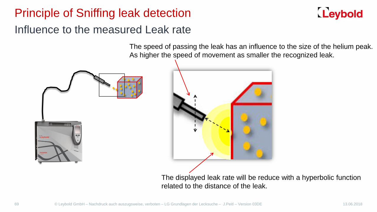
Principle of Sniffing leak detection Influence to the measured Leak rate
The speed of passing the leak has an influence to the size of the helium peak. As higher the speed of movement as smaller the recognized leak.
The displayed leak rate will be reduce with a hyperbolic function related to the distance of the leak.

13.06.2018 © Leybold GmbH – Nachdruck auch auszugsweise, verboten – LG Grundlagen der Lecksuche – J.Peitl – Version 03DE 70
Principle of Sniffing leak detection Sniffing lines
1. The standard sniffer line is designed with a length of 4 m so that it can be connected directly to the vacuum inlet of the leak detector. At the LD itself, a reduced pressure as atmospheric pressure arises due to the line length and the line diameter. This pressure is about 1mbar. This is achieved with an air-gas throughput of approximately q = 0.2 mbar l / s.
2. The technology can no longer be realized with longer cable lengths of 10 m and 20 m even up to 50 m. Such line lengths necessarily have a dead time during the signal display. This should be as short as possible for the operator. For this reason, an auxiliary pump (diaphragm) with continuous gas delivery and a relatively large air-gas flow of approx. q = 2 mbar l / s is used here. (QT 100) The gas inlet is effected by a helium-permeable diaphragm.
Quick-Test QT 100

Thank you for your attention!