LEAD FREE MasterSeries LF860 - Amazon S3 · This assembly shall be fitted with AWWA Compliant ......
4
ES-F-LF860L MasterSeries ® LF860 Reduced Pressure Zone Backflow Prevention Assemblies Size: 2 1 ⁄ 2" - 10" (65mm - 250mm) Series LF860 Reduced Pressure Zone Assembly LEAD FREE * The FEBCO MasterSeries LF860 Reduced Pressure Zone Assembly is specifi- cally designed to protect against possible backpressure and backsiphonage conditions for high hazard [i.e., toxic] application in accordance with Local Governing Water Utility Code. This Backflow Prevention Assembly is primarily used on potable drinking water systems where Local Governing Code man- dates protection from non-potable water being pumped or siphoned back into the potable water system. The LF860 features Lead Free* construction to comply with low lead installa- tion requirements. The Lead Free* Reduced Pressure Zone Assemblies shall comply with state codes and standards, where applicable, requiring reduced lead content. Features • Inline Serviceable Assembly • No Special Tools Required for Servicing • Captured Modular Spring Assembly • Reversible & Replaceable Discs • Field Replaceable Seats • Ductile Iron Valve Body Design • Stainless Steel Check Components • Modular Pressure Differential Relief Valve • Repairable Pressure Differential Relief Valve • Clapper Check Assembly • Captured O-ring Design Specifications The FEBCO MasterSeries LF860 Reduced Pressure Zone Assembly shall be installed on the potable water supply and at each point of cross-connection to protect against possible backpressure and backsiphonage conditions for high hazard [i.e., toxic] applications. The assembly shall consist of a main line valve body composed of a pressure differential relief valve located in a zone between two (2) independently acting approved clapper style check modules with replaceable seats and disc rubbers. Servicing of the pres- sure differential relief valve and both check modules does not require any special tools; both check modules are accessed through independently top entry covers. This assembly shall be fitted with AWWA Compliant inlet/outlet resilient seated shutoff valves; when used on a Fire-Sprinkler application, the assembly shall be fitted with approved UL/FM inlet/outlet resilient seated shutoff valves and contain four (4) properly located resilient seated test cocks as specified by AWWA Standard C511. Flow and pressure loss performance parameters shall meet the requirements of AWWA Standard C511. SPECIFICATION SHEET Job Name ––––––––––––––––––––––––––––––––––––––––––– Contractor –––––––––––––––––––––––––––––––––––––––––––– Job Location ––––––––––––––––––––––––––––––––––––––––– Approval ––––––––––––––––––––––––––––––––––––––––––––– Engineer –––––––––––––––––––––––––––––––––––––––––––– Contractor’s P.O. No. –––––––––––––––––––––––––––––––––– Approval –––––––––––––––––––––––––––––––––––––––––––– Representative –––––––––––––––––––––––––––––––––––––––– FEBCO product specifications in U.S. customary units and metric are approximate and are provided for reference only. For precise measurements, please contact FEBCO Technical Service. FEBCO reserves the right to change or modify product design, construction, specifications, or materials without prior notice and without incurring any obligation to make such changes and modifications on FEBCO products previously or subsequently sold. *The wetted surface of this product contacted by consumable water contains less than 0.25% of lead by weight. NOTICE Inquire with governing authorities for local installation requirements NOTICE The information contained herein is not intended to replace the full product installation and safety information available or the experience of a trained product installer. You are required to thoroughly read all installation instruc- tions and product safety information before beginning the installation of this product.
-
Upload
nguyenquynh -
Category
Documents
-
view
213 -
download
0
Transcript of LEAD FREE MasterSeries LF860 - Amazon S3 · This assembly shall be fitted with AWWA Compliant ......

ES-F-LF860L
MasterSeries® LF860Reduced Pressure Zone Backflow Prevention AssembliesSize: 21⁄2" - 10" (65mm - 250mm)
Series LF860 Reduced Pressure Zone Assembly
LEAD FREE*
The FEBCO MasterSeries LF860 Reduced Pressure Zone Assembly is specifi-cally designed to protect against possible backpressure and backsiphonage conditions for high hazard [i.e., toxic] application in accordance with Local Governing Water Utility Code. This Backflow Prevention Assembly is primarily used on potable drinking water systems where Local Governing Code man-dates protection from non-potable water being pumped or siphoned back into the potable water system.
The LF860 features Lead Free* construction to comply with low lead installa-tion requirements. The Lead Free* Reduced Pressure Zone Assemblies shall comply with state codes and standards, where applicable, requiring reduced lead content.
Features• InlineServiceableAssembly• NoSpecialToolsRequiredforServicing• CapturedModularSpringAssembly• Reversible&ReplaceableDiscs• FieldReplaceableSeats• DuctileIronValveBodyDesign• StainlessSteelCheckComponents• ModularPressureDifferentialReliefValve• RepairablePressureDifferentialReliefValve• ClapperCheckAssembly• CapturedO-ringDesign
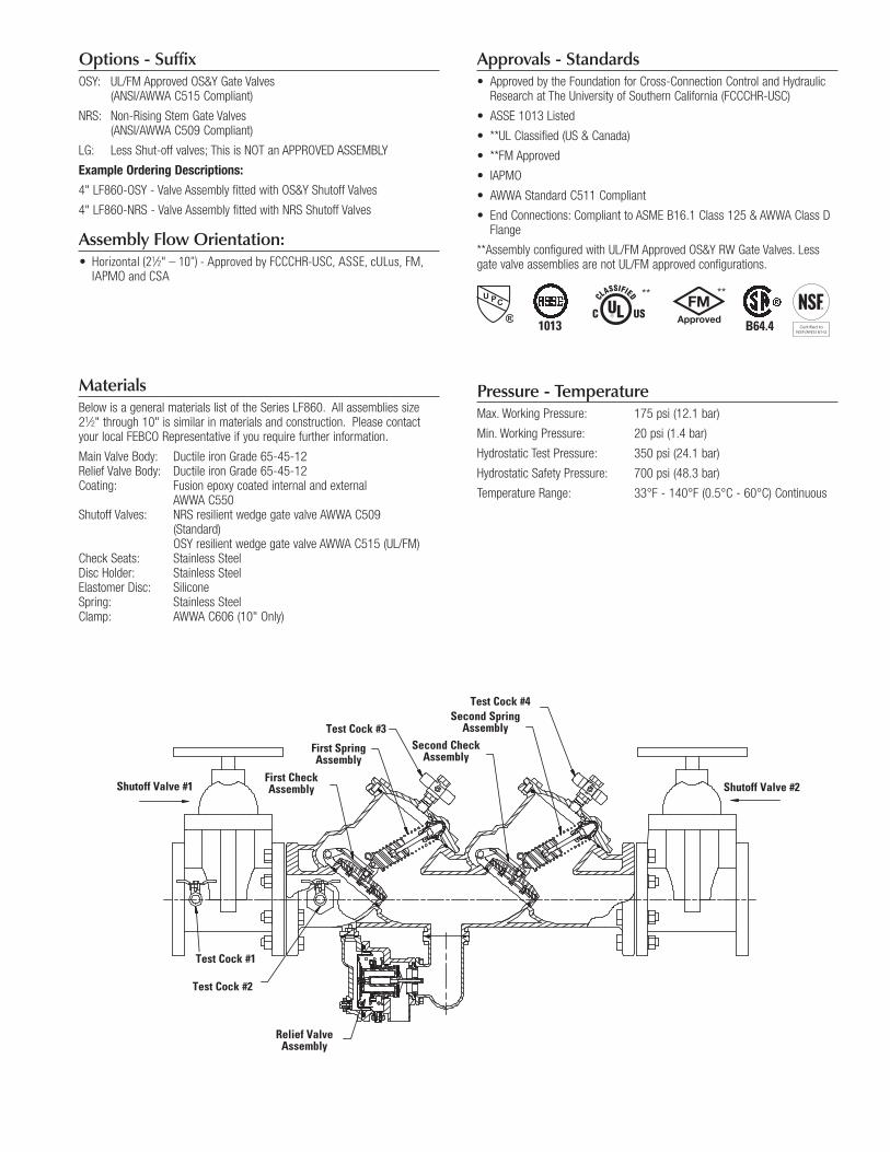
SpecificationsThe FEBCO MasterSeries LF860 Reduced Pressure Zone Assembly shall be installed on the potable water supply and at each point of cross-connection to protect against possible backpressure and backsiphonage conditions for high hazard [i.e., toxic] applications. The assembly shall consist of a main line valve body composed of a pressure differential relief valve located in a zone between two (2) independently acting approved clapper style check modules with replaceable seats and disc rubbers. Servicing of the pres-sure differential relief valve and both check modules does not require any special tools; both check modules are accessed through independently top entry covers. This assembly shall be fitted with AWWA Compliant inlet/outlet resilient seated shutoff valves; when used on a Fire-Sprinkler application, the assembly shall be fitted with approved UL/FM inlet/outlet resilient seated shutoff valves and contain four (4) properly located resilient seated test cocks as specified by AWWA Standard C511. Flow and pressure loss performance parameters shall meet the requirements of AWWA Standard C511.
S P E C I F I C AT I O N S H E E T
Job Name ––––––––––––––––––––––––––––––––––––––––––– Contractor ––––––––––––––––––––––––––––––––––––––––––––
Job Location ––––––––––––––––––––––––––––––––––––––––– Approval –––––––––––––––––––––––––––––––––––––––––––––
Engineer –––––––––––––––––––––––––––––––––––––––––––– Contractor’s P.O. No. ––––––––––––––––––––––––––––––––––
Approval –––––––––––––––––––––––––––––––––––––––––––– Representative ––––––––––––––––––––––––––––––––––––––––
FEBCO product specifications in U.S. customary units and metric are approximate and are provided for reference only. For precise measurements, please contact FEBCO Technical Service. FEBCO reserves the right to change or modify product design, construction, specifications, or materials without prior notice and without incurring any obligation to make such changes and modifications on FEBCO products previously or subsequently sold.
*The wetted surface of this product contacted by consumable water contains less than 0.25% of lead by weight.
NOTICEInquirewithgoverningauthoritiesforlocalinstallationrequirements
NOTICEThe information contained herein is not intended to replace the full product installation and safety information available or the experience of a trained product installer. You are required to thoroughly read all installation instruc-tions and product safety information before beginning the installation of this product.
Options - SuffixOSY: UL/FMApprovedOS&YGateValves
(ANSI/AWWAC515Compliant)
NRS: Non-RisingStemGateValves (ANSI/AWWAC509Compliant)
LG: LessShut-offvalves;ThisisNOTanAPPROVEDASSEMBLY
Example Ordering Descriptions:
4"LF860-OSY-ValveAssemblyfittedwithOS&YShutoffValves
4"LF860-NRS-ValveAssemblyfittedwithNRSShutoffValves
Assembly Flow Orientation:• Horizontal(21⁄2"–10")-ApprovedbyFCCCHR-USC,ASSE,cULus,FM,IAPMOandCSA
MaterialsBelow is a general materials list of the Series LF860. All assemblies size 21⁄2" through 10" is similar in materials and construction. Please contact your local FEBCO Representative if you require further information.
MainValveBody: DuctileironGrade65-45-12 ReliefValveBody: DuctileironGrade65-45-12 Coating: Fusion epoxy coated internal and external AWWA C550 ShutoffValves: NRSresilientwedgegatevalveAWWAC509 (Standard) OSY resilient wedge gate valve AWWA C515 (UL/FM) Check Seats: Stainless Steel DiscHolder: StainlessSteel ElastomerDisc: Silicone Spring: Stainless Steel Clamp: AWWA C606 (10" Only)
Approvals - Standards• ApprovedbytheFoundationforCross-ConnectionControlandHydraulic
ResearchatTheUniversityofSouthernCalifornia(FCCCHR-USC)
• ASSE1013Listed
• **ULClassified(US&Canada)
• **FMApproved
• IAPMO
• AWWAStandardC511Compliant
• EndConnections:ComplianttoASMEB16.1Class125&AWWAClassDFlange
**AssemblyconfiguredwithUL/FMApprovedOS&YRWGateValves.Lessgate valve assemblies are not UL/FM approved configurations.
Pressure - TemperatureMax. Working Pressure: 175 psi (12.1 bar)
Min. Working Pressure: 20 psi (1.4 bar)
HydrostaticTestPressure: 350psi(24.1bar)
HydrostaticSafetyPressure: 700psi(48.3bar)
TemperatureRange: 33°F-140°F(0.5°C-60°C)Continuous
Relief Valve Assembly
Test Cock #3
Test Cock #4
Test Cock #2
Test Cock #1
Shutoff Valve #1 Shutoff Valve #2First Check Assembly
First Spring Assembly
Second Spring Assembly
Second Check Assembly
1013 B64.4
** **

Dimensions & WeightsBelow are the nominal dimensions and physical weights for the Series LF860 size 21⁄2" through 10". Allowances must be made for normal manufacturing tolerances. Please visit our website to download a copy of this product’s installation instructions, or contact your local FEBCO Representative for more information.
LF860
SIZE (DN) DIMENSIONS WEIGHT***
A B C D E* F** G H NRS OSY
in. mm in. mm in. mm in. mm in. mm in. mm in. mm in. mm in. mm lbs. kg. lbs. kg.
21⁄2 65 403⁄4 1035 251⁄2 648 10 254 10 254 125⁄8 321 163⁄8 416 41⁄2 114 71⁄8 181 250 113 254 115
3 80 417⁄8 1064 255⁄8 651 10 254 10 254 127⁄8 327 221⁄4 565 41⁄2 114 73⁄8 187 276 125 280 127
4 100 461⁄4 1175 28 711 101⁄8 257 101⁄8 257 143⁄8 365 231⁄4 591 51⁄2 140 81⁄8 206 335 152 347 157
6 150 56 1422 343⁄4 883 123⁄4 324 111⁄8 283 187⁄8 479 301⁄8 765 61⁄2 165 97⁄8 251 503 228 523 237
8 200 65 1651 413⁄4 1061 155⁄8 397 121⁄4 311 231⁄2 597 373⁄4 959 7 178 111⁄8 283 807 366 835 379
10 250 725⁄8 1845 463⁄8 1178 155⁄8 397 123⁄8 314 271⁄2 699 48 1219 9 229 123⁄8 314 1205 547 1243 564
* Indicates nominal dimensions with NRS Gate Valves** Indicates nominal dimensions with OSY Gate Valves (Full Open Position)*** Indicates weight of complete Backflow Assemblies with specified Gate Valves
The gap drain is not designed to catch the maximum discharge possible from the relief valve. The installation of the FEBCO air gap with the drain line terminating above a floor drain will handle any normal discharge or nuisance spitting through the relief valve. However, floor drain size may need to be designed to prevent water damage caused by a catastrophic failure condition. Do not reduce the size of the drain line from the air gap fitting.
A
B
E*C
D
F**
E*
F**
D
A
B
C
G
H

ES-F-LF860L 1515 © 2015 FEBCO
PerformanceFlow capacity chart identifies valve performance based upon rated water Velocityupto20fps
• MaximumserviceflowrateisdeterminedbymaximumratedVelocityof7.5fps.
• AWWAManualM-22(AppendixC)recommendsthatthemaximumwaterVelocityintheservicesbenotmorethan10fps.
• ULflowrateisdeterminedbytypicallyratedVelocityof15feet/sec.
USA: Tel: (800) 767-1234 • Fax: (800) 788-4491 • FEBCOonline.comCanada: Tel: (905) 332-4090 • Fax: (905) 332-7068 • FEBCOonline.ca
Latin America: (52) 81-1001-8600 • Fax: (52) 81-8000-7091 • FEBCOonline.com
A Watts Water Technologies Company
21⁄2" LF860
3" LF860
4" LF860
6" LF860
8" LF860
10" LF860
psi
22 20 18 16 14 12 10 8 6 4 2 0
psi
22 20 18 16 14 12 10 8 6 4 2 0
psi 18 16 14 12 10 8 6 4 2 0
psi 18 16 14 12 10 8 6 4 2 0
psi
18 16 14 12 10 8 6 4 2 0
psi
18 16 14 12 10 8 6 4 2 0
0 25 50 75 100 125 150 175 200 225 250 275 300 325 350 gpm 284 568 852 1136 lpm 7.5 14.7 22.0 fps
0 50 100 150 200 250 300 350 400 450 500 gpm 379 757 1136 1514 lpm 7.5 14.5 22.0 fps
0 100 200 300 400 500 600 700 800 gpm 379 1136 1893 2650 lpm 7.5 12.8 19.1 fps
0 200 400 600 800 1000 1200 1400 1600 gpm 757 2271 3785 5300 lpm 7.5 11.4 17.0 fps
0 400 800 1200 1600 2000 2400 gpm 1514 3028 4543 6057 7571 9085 lpm 7.5 10.5 15.3 fps
0 600 1200 1800 2400 3000 3600 gpm 2271 4543 6814 9085 11356 13627 lpm 7.5 9.4 14.1 fps
Service Flow
Service Flow
Service Flow
Service Flow
Service Flow
Service Flow
Rated Flow
Rated Flow
Rated Flow
Rated Flow
Rated Flow
Rated Flow
*UL Rated Flow
*UL Rated Flow
*UL Rated Flow
*UL Rated Flow
*UL Rated Flow
*UL Rated Flow
Capacity
PSI D
rop
(*Fr
ictio
n Lo
ss)
PSI D
rop
(*Fr
ictio
n Lo
ss)
PSI D
rop
(*Fr
ictio
n Lo
ss)
PSI D
rop
(*Fr
ictio
n Lo
ss)
PSI D
rop
(*Fr
ictio
n Lo
ss)
PSI D
rop
(*Fr
ictio
n Lo
ss)