LEAD ACID BATTERY CHARGER KIT - · PDF fileLEAD ACID BATTERY CHARGER KIT Ramsey ......
24
LEAD ACID BATTERY CHARGER KIT Ramsey Electronics Model No. LABC1 An educational kit that will come in handy around the shop and garage. Build your own charger instead of shelling out big bucks for a “store bought” unit. You might learn more than you ever wanted to know about batteries and battery charging. Amaze your friends with your new found knowledge. Wait . . .is that Regis on the phone? • No more fried gel cells! • Extends the life of your 12 volt lead acid batteries. • Automatic ambient temperature compensation. • Automatically adjusts charge voltage depending on battery status. • Bright front panel charge indicator. • Saves spending money on costly replacement batteries; pays for itself in no time! • Add our matching case and knob set for a professional appearance.
Transcript of LEAD ACID BATTERY CHARGER KIT - · PDF fileLEAD ACID BATTERY CHARGER KIT Ramsey ......

LABC1 • 1
LEAD ACID BATTERY CHARGER KIT
Ramsey Electronics Model No. LABC1
An educational kit that will come in handy around the shop and garage. Build your own charger instead of shelling out big bucks for a “store bought” unit. You might learn more than you ever wanted to know about batteries and battery charging. Amaze your friends with your new found knowledge. Wait . . .is that Regis on the phone?
• No more fried gel cells!
• Extends the life of your 12 volt lead acid batteries.
• Automatic ambient temperature compensation.
• Automatically adjusts charge voltage depending on battery status.
• Bright front panel charge indicator.
• Saves spending money on costly replacement batteries; pays for itself in no time!
• Add our matching case and knob set for a professional appearance.

LABC1 • 2
RAMSEY TRANSMITTER KITS • FM100B Professional FM Stereo Transmitter • FM25B Synthesized Stereo FM Transmitter • MR6 Model Rocket Tracking Transmitter • TV6 Television Transmitter • Cube Television Transmitters RAMSEY RECEIVER KITS • FR1 FM Broadcast Receiver • AR1 Aircraft Band Receiver • SR2 Shortwave Receiver • SC1 Shortwave Converter RAMSEY HOBBY KITS • SG7 Personal Speed Radar • SS70A Speech Scrambler • BS1 “Bullshooter” Digital Voice Storage Unit • AVS10 Automatic Sequential Video Switcher • WCT20 Cable Wizard Cable Tracer • ECG1 Heart Monitor Kit • TFM3 Tri-Field Meter RAMSEY AMATEUR RADIO KITS • DDF1 Doppler Direction Finder • HR Series HF All Mode Receivers • QRP Series HF CW Transmitters • CW7 CW Keyer • CPO3 Code Practice Oscillator • QRP Power Amplifiers RAMSEY MINI-KITS Many other kits are available for hobby, school, Scouts and just plain FUN. New kits are always under development. Write or call for our free Ramsey catalog.
LABC1 KIT INSTRUCTION MANUAL Ramsey Electronics publication No. MLABC1 Rev 1.2
First printing: November 2001 COPYRIGHT 2001 by Ramsey Electronics, Inc. 590 Fishers Station Drive, Victor, New York 14564. All rights reserved. No portion of this publication may be copied or duplicated without the written permission of Ramsey Electronics, Inc. Printed in the United States of America.

LABC1 • 3
LEAD ACID BATTERY CHARGER KIT
Ramsey Publication No. MLABC1 Price $5.00
Quick Battery Theory ..................4 Circuit Description .......................6 Schematic Diagram ....................8 Parts Layout Diagram .................9 Parts List ....................................10 Kit Assembly ...............................12 Custom Case Assembly .............15 Adjusting your LABC1 .................17 Safety Considerations .................18 Troubleshooting Guide ...............19 Warranty .....................................23
KIT ASSEMBLY AND INSTRUCTION MANUAL FOR
RAMSEY ELECTRONICS, INC. 590 Fishers Station Drive
Victor, New York 14564 Phone (585) 924-4560
Fax (585) 924-4555 www.ramseykits.com
TABLE OF CONTENTS

LABC1 • 4
Quick Battery Theory
To begin, we should cover a few facts about lead acid batteries in general.
Most traditional historians date the invention of batteries to the early 1800’s when experiments by Alessandro Volta generated electrical current from chemical reactions between dissimilar metals. Volta’s original ‘voltaic pile’ consisted of zinc and silver disks separated by a porous nonconductive material saturated with seawater. When stacked in a particular manner, a voltage could be measured across each silver and zinc disk.
Other more radical thinkers, however, believe that lead acid battery technology has been around since the early days of the Egyptian Pharaohs! Whether they discovered the electro-chemical process on their own or if the ‘Space Aliens’ using their pyramids as an intergalactic spaceport taught them still requires a bit more clarification. We’ll leave that one for you to follow up on!
While advances in construction and materials have come a long way over the years, the basic principles still apply. Lead acid cells of all types (‘Wet’ or ‘VRLA’ ) undergo a specific set of chemical reactions while charging and discharging. They are also formed from similar types of active materials. For the most part, lead acid batteries are made up of lead plates submerged in a sulfuric acid solution. The positive electrode plates are formed from lead dioxide (PbO2) while the negative electrodes are made of sponge metallic lead (Pb). The porous nature of the lead plates allows the electrolyte, a dilute mixture of 35% sulfuric acid and 65% water, to efficiently contact the maximum surface area and obtain the most charge carriers. The electrolyte solution provides the sulfate ions formed during the discharge chemical reaction process giving us the electrons needed for current flow into the load.
One of the byproducts created during the discharge process of freeing sulfate ions is lead sulfate (PbSO4). As the battery discharges, the lead sulfate attaches to the electrode plates raising the internal resistance of the battery which in turn lowers its working terminal voltage.
To determine the SOC (State Of Charge) of a lead acid battery, the classic voltmeter approach does not work well. The terminal voltage will vary widely between batteries as a function of things like ambient temperature and the relative age of the battery. A full set of temperature profile tables would show big differences in the open circuit terminal voltage over a wide temperature range. This is why a good charger must incorporate a temperature compensation network to avoid ‘over’ or ‘under’ charging the battery at different ambient temperatures. To test a lead acid battery’s SOC, the best indicator is a hydrometer. When you test a battery’s SOC with a hydrometer, you are actually measuring the amount of sulfuric acid left in the electrolyte
LABC1 • 5
solution. As more energy is drained from the battery, the ratio of sulfuric acid to water decreases and the created lead sulfate byproduct begins forming on the electrode plates. A low hydrometer reading means the chemical makeup that generates the free electrons is diminished so not as much energy is stored for use.
The term ‘specific gravity’ is often used to benchmark a lead acid battery’s SOC. The specific gravity of a substance is a comparison of its density to that of water (1.000). Imagine a one gallon bottle filled with water and a second filled with feathers. There are equal volumes of material present in both but the bottle with the feathers will weigh less than that containing the water. The resultant specific gravity value of the bottle of feathers would be less than that of the bottle of water. With lead acid batteries, the sulfur atoms break down and leach out of the electrolyte solution as it discharges. The breakdown of the electrolyte reduces its overall ‘weight’ as the sulfur is removed from the solution thus reducing the specific gravity measurement. Take a look at Table 1.
Great care should be taken to avoid discharging a battery beyond the 75% SOC point. Once the specific gravity drops below the 1.210 level, excessive sulfate deposits form on the electrode plates. This process is called ‘sulfation’ and leads to the hardening of the electrode plates. If the battery is kept in a low charge state for long a period of time, the sulfation process will eventually reduce the ability of the battery to generate ion charge carries to the point that it no longer provides the needed power. This point is otherwise known as a DEAD BATTERY! When you recharge the battery, the process is reversed and the sulfur returns to the electrolyte solution. Proper cycling of the battery will ensure a long and functional life. If the battery is abused by allowing sulfation of the electrode
State Of Charge
Specific Gravity
Open-Circuit Voltage
(approximate)
100% 1.265 12.63
75% 1.210 12.30
50% 1.160 12.00
25% 1.120 11.76
0% 1.100 11.64
State of Charge as related to Specific Gravity and Open-Circuit Voltage
Table 1.
LABC1 • 6
plates on a regular basis or over an extended period of time, the charging process will not be able to restore the battery to its former full potential. Time to make a costly battery replacement!
Circuit Description
The LABC1 has been designed as a dependable workhorse to charge and hold your 12 Volt lead acid batteries at their peak level, insuring a long life and maximum performance. The charging procedure used when working with a flooded ‘wet’ cell battery or one of the newer VRLA (Valve Regulated Lead Acid – ‘Gel’ or ‘AGM’) batteries is the same. The battery being charged will automatically set the LABC1 in one of two charging modes upon hookup. The circuit design takes into account the battery’s current SOC (State Of Charge) and adjusts the terminal voltage at J2 accordingly. The main charging circuit is very simple because as we discussed before, the concept of lead acid batteries has been around for centuries (give or take a few thousand years if you don’t believe in the ‘Space Alien’ theory). The real secret to correctly charging a lead acid battery system is to use a temperature compensated voltage source that automatically varies its output in accordance with the batteries SOC. ‘Frying’ your battery occurs when the charging unit fails to sense that the electro-chemical rejuvenation (or charging) process has slowed to the point that the higher voltage charging mode should end. Continual high voltage charging will decrease the overall life of the battery.
Let’s take a closer look at the LABC1 schematic and see what’s happening.The power supply inlet for the LABC1 is J1. The input voltage is immediately presented to a full wave bridge rectifier consisting of diodes D1 to D4 and then filtered by C1 to reduce the voltage ripple. Using a bridge configuration on the voltage input allows the user more options to power their LABC1. The use of a 14 VAC or 20 VDC (positive tip) power supply will do nicely with any 12 Volt lead acid battery. Varying your power supplies current capacity will allow you to charge any type of lead acid battery without a problem. Most of the standard cells require a charging current of 650mA or greater. For these systems a 14 VAC (2 Amps or so) transformer will work very well. If your application is to charge very small capacity batteries with a maximum charge current of only a few hundred milliamps, using a 14 VAC @ 500mA ‘wall wart’ supply or a current limited bench-top power supply set for 20 VDC will avoid excessive current draw that could damage a heavily discharged battery. Internal heating from excessive charge current will also degrade your overall battery life.
Moving on, VR1 is a voltage regulator that provides the precision terminal voltage we need to charge the lead acid cells. Unlike a standard voltage regulator that is designed for a fixed level output, VR1 lends itself well as a variable voltage source. With a maximum current source capability of about 1.3 amps, VR1 gives the user the flexibility to charge even very large capacity

LABC1 • 7
batteries. Granted, that might take a while.
The other support components on the board help VR1 to know when to adjust its output voltage up or down to ensure the proper charging rate of the battery. These other components are grouped into two major sections, the SOC feedback loop and the ambient temperature compensation used during the ‘Float’ mode after the battery has been fully charged.
The SOC feedback loop consists mainly of U1 and R6 together to form a low voltage comparator in conjunction with R1 and R4 to set the range of the charging voltage. Here’s how the loop functions. Assume for starters that the battery under charge, or BUC (not to be confused with your BUT, or Battery Under Test) is discharged and drawing enough current to set the LABC1 in charge mode. After the current drawn by the battery drops below a certain point, the need for ‘high’ voltage charging has ended. U1 monitors the voltage drop across R6 to determine when to switch VR1’s output at J2 from 14.4V (‘Charge’ mode) to 13.4V (‘Float’ mode). As the battery comes to a full charge, the charging current it draws drops below about 150mA. The voltage across R6 (0.47 ohms) will then fall below 0.07V thanks to Ohm’s Law, V=IxR. This trigger point causes the V+ pin (U1:1) to toggle from its ‘Charging’ mode ‘high’ value of about 12.8V to a charged ‘Float’ mode ‘low’ value of about 0.7V. When V+ (U1:1) toggles low, R4 is switched into the reference feedback circuit of VR1 causing its output voltage drop back to 13.4V. The ‘Charged’ LED (D15) is turned on when the Base-Emitter junction of Q1 is thus forward biased indicating that the battery is charged and is being ‘topped-off’ by the ‘Float’ mode operation.
Now that the battery is charged, the ambient temperature compensation circuit comes into play. The effects of this circuit, formed by R2, R3 and diodes D5 to D14, are used only during the ‘Float’ mode operation to adjust the terminal voltage in accordance with the ambient temperature. If the temperature is not factored in, you would run the risk of over-charging the battery when it’s hot or under-charging the battery when it’s cold. Taking advantage of the thermal characteristics of a PN diode (∆2.2mV/°C), the diode matrix (D5 to D14) raises or lowers the reference terminal of VR1 by 22mV (10 x 2.2mV/°C) for every 1°C change. This is just the right negative temperature compensation we needed to properly charge our lead acid batteries!
At the start of the charge cycle, you’ll notice that the heatsink used with VR1 can get very warm if you are charging a large capacity battery. The fact that the temperature sensor matrix is on the same circuit board and in the same case will not negatively affect the compensation network because there will be very little dissipated heat by the board components once the unit switches into ‘Float’ mode. The drop in charge current drawn by the battery is so low by the time ‘Float’ mode is entered, the air cavity around the temperature sensor diodes will re-acclimate to the surrounding ambient temperature.

LABC1 • 8
LABC1 • 9
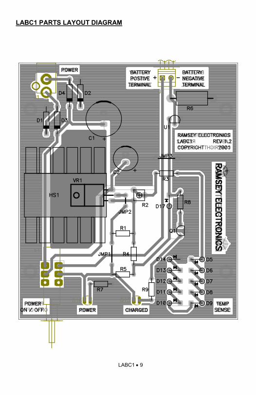
LABC1 PARTS LAYOUT DIAGRAM

LABC1 • 10
PARTS SUPPLIED WITH YOUR LABC1 KIT Capacitors
1 10 µF electrolytic capacitor [C2] 1 1000 µF electrolytic capacitor [C1]
Resistors and Potentiometers
1 0.47 ohm, 1 watt (yellow-violet-silver) [R6] 1 270 ohm (red-violet-brown) [R1] 3 820 ohm (gray-red-brown) [R3,7,9] 1 10K ohm (brown-black-orange) [R8] 1 18K ohm (brown-gray-orange) [R4] 1 PC mount 1K ohm potentiometer (marked 102) [R2]
Semiconductors and Integrated Circuits
11 1N4148 diodes (small glass diode) [D5,6,7,8,9,10,11,12,13,14,17] 4 1N4002 or 1N4004 diodes (black with white band) [D1,2,3,4] 1 221334 transistor (three leads TO-92 package marked 221334) [Q1] 2 JUMBO red LEDs [D15,16] 1 LM317 3 terminal adjustable regulator [VR1] 1 LM334 IC (three leads TO-92 package marked LM334) [U1]
Miscellaneous Components
1 2.1mm power jack [J1] 1 DPDT PC mount pushbutton switch [S1] 1 Heatsink [HS1] 1 #4-40 3/8” screw (for HS1) 1 #4-40 Kep nut (for HS1) 1 2 Screw terminal jack [J2] 2’ #24 AWG Dual (red & black) twisted hookup wire
LABC1 • 11
RAMSEY "Learn-As-You-Build KIT ASSEMBLY There are numerous solder connections on the LABC1 printed circuit board. Therefore, PLEASE take us seriously when we say that good soldering is essential to the proper operation of your battery charger kit! • Use a 25-watt soldering pencil with a clean, sharp tip. • Use only rosin-core solder intended for electronics use. • Use bright lighting; a magnifying lamp or bench-style magnifier may
be helpful. Do your work in stages, taking breaks to check your work. Carefully brush away wire cuttings so they don't lodge between solder connections. We have a two-fold strategy for the order of the following kit assembly steps. First, we install parts in physical relationship to each other, so there's minimal chance of inserting wires into wrong holes. Second, whenever possible, we install in an order that fits our "Learn-As-You Build" Kit building philosophy. This entails describing the circuit that you are building, instead of just blindly installing components. We hope that this will not only make assembly of our kits easier, but help you to understand the circuit you’re constructing. For each part, our word "Install" always means these steps: 1. Pick the correct component with the proper value to start with. 2. Insert it into the correct PC board location. 3. Orient it correctly, following the PC board drawing and the written directions for all parts - especially when there's a right way and a wrong way to solder it in. (Diode bands, electrolytic capacitor polarity, transistor shapes, dotted or notched ends of IC's, and so forth.) 4. Solder all connections unless directed otherwise. Use enough heat and solder flow for clean, shiny, completed connections. 5. Trim or nip the excess component lead wire after soldering. NOTE: Save some of the longer wire scraps nipped from resistors and capacitors. These will be used to form wire jumpers (JMP1, etc.) to be soldered in just like parts during these construction steps.
Enough of that ... let’s get started!

LABC1 • 12
LABC1 BATTERY CHARGER KIT ASSEMBLY Although we know that you are anxious to complete the assembly of your battery charger kit it is best to follow the step-by-step instructions. Try to avoid the urge to jump ahead installing components. Since you may appreciate some warm-up soldering practice as well as a chance to put some landmarks on the PC board, we’ll first install a couple of the larger components. This will also help us to get acquainted with the up-down, left-right orientation of the circuit board. Remember that the components will be mounted on the component side of the circuit board and soldered on the solder side of the circuit board, the side that contains the printed circuit traces. Have a look at the parts layout diagram to help with your assembly. Use the boxes to check off your progress.
Check all received parts against the parts list. The parts list describes the various markings that may be found on the kit parts. Carefully sort the parts into small piles, (an empty egg tray does nicely for this purpose) to aid in finding the correct part at the required time.
1. Install DPDT PC mount pushbutton switch, S1. Be sure it is seated properly before soldering all 6 pins.
2. Install J1, the 2.1mm power jack.
We’ll begin to install some of the polarity sensitive parts at this point. Use the parts layout diagram in addition to the PC board silkscreen to orient the diodes, electrolytic capacitors, transistors and ICs properly.
3. Install D1, 1N4002 diode (black with white band). You’ll see a black band on the PC board silkscreen. Line up the white band on the diode with this black band. This is the cathode side of the diode.
4. Install D2, D3 and D4, 1N4002 diodes (black with white band) in the same manner as you did D1 above. Carefully orient the banded end before soldering these diodes.
Cathode Anode
LABC1 • 13
5. Install C1, 1000 µF electrolytic capacitor. This part also must be installed properly to function. In fact, this capacitor has the potential to explode if installed in reverse polarity. The PC board silkscreen shows the positive hole and the band on the capacitor shows the negative side. You’ll also note that the lead closest to the stripe is shorter than the other lead; this also indicates the negative side. Save the long leads you clip off from this part. They’re great for the jumpers you’ll need to install later.
Next we’ll install VR1. You’ll need to locate the following parts: the LM317, HS1 is the black finned heatsink, the #4-40 3/8” screw, and the #4-40 kep nut.
6. Install VR1, the LM317, 3 terminal adjustable regulator. Place the heatsink, HS1, on the circuit board, lining it up with the silkscreen so that the hole in the heatsink matches the hole in the board. Take the LM317 and place it on top of the heatsink so that the hole in the regulator lines up with the other two. This will show you where to bend the leads down so that the part fits in the PC board holes and lays flat on the heatsink. This allows maximum “bleed off” of heat from the part. Once the leads are bent and through their PC board holes, take the screw and nut and attach the LM317 and the heatsink to the board. It is easiest to put the screw through the top of the components and tighten the nut on the bottom of the board. Once the screw is holding everything in place solder the three leads of the LM317.
7. Install J2, the 2 screw terminal jack. The openings should face the rear of the PC board. This is where the battery you’re charging will be attached to the LABC1.
8. Install R6, 0.47ohm 1 watt resistor (yellow-violet-silver). This part is physically larger than the other resistors in your kit for a reason; it is a 1 watt part compared to the other 1/4 watt parts. That means it needs to (and can!) dissipate more power than the others.
9. Install U1, the LM334 IC (three leads TO-92 package marked LM334). Also, keep a few more of those scrap leads handy as we will need a few more jumper wires later.
10. Install C2, 10 µF electrolytic capacitor. Watch that polarity!
11. Using a scrap component lead, form a jumper wire and install in the JMP3 holes. Jumpers act like electronic “bridges” that carry power or signals over active traces on the circuit trace side of the board. Solder both ends of the jumper into place.
12. Install R3, 820 ohms (gray-red-brown).
13. Take another scrap lead and install JMP2. It helps to pre-bend the wire into a staple shape before inserting into the PC board.
LABC1 • 14
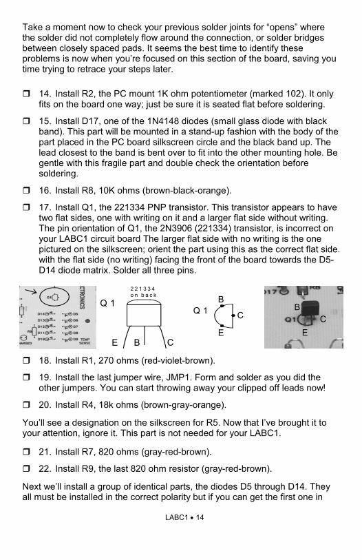
Take a moment now to check your previous solder joints for “opens” where the solder did not completely flow around the connection, or solder bridges between closely spaced pads. It seems the best time to identify these problems is now when you’re focused on this section of the board, saving you time trying to retrace your steps later.
14. Install R2, the PC mount 1K ohm potentiometer (marked 102). It only fits on the board one way; just be sure it is seated flat before soldering.
15. Install D17, one of the 1N4148 diodes (small glass diode with black band). This part will be mounted in a stand-up fashion with the body of the part placed in the PC board silkscreen circle and the black band up. The lead closest to the band is bent over to fit into the other mounting hole. Be gentle with this fragile part and double check the orientation before soldering.
16. Install R8, 10K ohms (brown-black-orange).
17. Install Q1, the 221334 PNP transistor. This transistor appears to have two flat sides, one with writing on it and a larger flat side without writing. The pin orientation of Q1, the 2N3906 (221334) transistor, is incorrect on your LABC1 circuit board The larger flat side with no writing is the one pictured on the silkscreen; orient the part using this as the correct flat side. with the flat side (no writing) facing the front of the board towards the D5-D14 diode matrix. Solder all three pins.
18. Install R1, 270 ohms (red-violet-brown).
19. Install the last jumper wire, JMP1. Form and solder as you did the other jumpers. You can start throwing away your clipped off leads now!
20. Install R4, 18k ohms (brown-gray-orange).
You’ll see a designation on the silkscreen for R5. Now that I’ve brought it to your attention, ignore it. This part is not needed for your LABC1.
21. Install R7, 820 ohms (gray-red-brown).
22. Install R9, the last 820 ohm resistor (gray-red-brown).
Next we’ll install a group of identical parts, the diodes D5 through D14. They all must be installed in the correct polarity but if you can get the first one in
EC
BQ 1
E B C
2 2 1 3 3 4o n b a c k
Q 1
E
C
B

LABC1 • 15
right, you can do it with the rest. These will all be mounted in stand-up fashion, just like D17 was a few steps ago. Again, the body of the part is placed in the hole with the circle around it and the other lead is bent up and around to fit into the other hole. The banded end should be facing up. If you don’t want to spend time desoldering later, check them carefully now. It might help to pre-bend all the diodes so that you can just grab them one at a time and place them on the board.
23. Install D5 through D9. Be sure you solder them all.
24. Install D10 through D14. Notice that the orientation has changed.
Now we’ll install the two LEDs. One indicates “power on” and the other indicates what mode your charger is in, whether charge or float mode. Both are oriented the same way and should be left sitting up off the circuit board so that they can be bent over to fit through the holes in the matching case.
24. Install D15 and D16. You’ll see that the LEDs have a flat side and so does the PC board silkscreen. Orient the flat sides correctly and slide the diodes into their mounting holes. One lead is shorter than the other, just like the electrolytic capacitors we installed earlier. This indicates the cathode or negative lead of the LED and should correspond to the hole closest to the flat side. Get them both lined up so that they are about the same height above the circuit board and bend the leads on the back of the board to hold them in place before soldering.
CONGRATULATIONS ! Great job! You’ve made it through the circuit board assembly of your LABC1 kit. We know you’re anxious to “fire it up” but take a moment to look over your work now, checking for imperfect solder joints, misplaced components and correct orientation of polarity sensitive parts. Even if you have to fix something, you’ll be glad you found it now and not after you turn on the power and let the magic smoke out of one of your parts!
Front View
LED
PC Board
Leave leads approximately 3/4 inch in lengthFlat
Front View after Bending
LED
PC Board
Leave leads approximately 3/4 inch in lengthFlat
LABC1 • 16
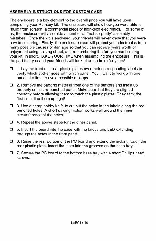
ASSEMBLY INSTRUCTIONS FOR CUSTOM CASE
The enclosure is a key element to the overall pride you will have upon completing your Ramsey kit. The enclosure will show how you were able to “build from scratch” a commercial piece of high-tech electronics. For some of us, the enclosure will also hide a number of “not-so-pretty” assembly mistakes. Once the kit is enclosed, your friends will never know that you were new to soldering. Finally, the enclosure case will protect your electronics from many possible causes of damage so that you can receive years worth of enjoyment using, talking about, and remembering the fun you had building your kit. In short, TAKE YOUR TIME when assembling the enclosure. This is the part that you and your friends will look at and admire for years!
1. Lay the front and rear plastic plates over their corresponding labels to verify which sticker goes with which panel. You’ll want to work with one panel at a time to avoid possible mix-ups.
2. Remove the backing material from one of the stickers and line it up properly on its pre-punched panel. Make sure that they are aligned correctly before allowing them to touch the plastic plates. They stick the first time; line them up right!
3. Use a sharp hobby knife to cut out the holes in the labels along the pre-punched holes. A short sawing motion works well around the inner circumference of the holes.
4. Repeat the above steps for the other panel.
5. Insert the board into the case with the knobs and LED extending through the holes in the front panel.
6. Raise the rear portion of the PC board and extend the jacks through the rear plastic plate. Insert the plate into the grooves on the base tray.
7. Secure the PC board to the bottom base tray with 4 short Phillips head screws.
LABC1 • 17
ADJUSTING YOUR LABC1 BATTERY CHARGER
Now that you have finished the assembly stage there is only one more step before you start charging your batteries. The necessary alignment is to adjust R2 for the proper ‘Float’ voltage with reference to the current air temperature around diodes D5 to D14. In order for the temperature compensation network to function properly and automatically adjust the ‘Float’ voltage as needed, you will need to know the air temperature in the room you are in. Note that this adjustment only needs to be done once. When R2 has been set, the unit will automatically track as needed from there on out.
To adjust R2, take a temperature reading for the current room temperature with a thermometer. Set your voltmeter on the 20VDC scale and attach the probes (Red = +, Black = -) across the output of J2. Trim the pot (R2) to get a reading of 13.4 VDC (+- 0.01 VDC) at a room temperature of 25°C (77°F) with no battery attached. If your room temperature is above or below 25°C, you will need to account for the difference by offsetting the alignment voltage by 22mV (10 x 2.2mV/°C for each of the sensor diodes) for every 1°C of difference. See Table 2 for examples.
If you do need to adjust for any temperature differences, here are a few helpful hints to point you in the right direction:
· If the temperature is higher than 25°C (77°F), reduce the alignment voltage at J2 by 22mV for each 1°C difference.
· If the temperature is lower than 25°C (77°F), increase the alignment voltage at J2 by 22mV for each 1°C difference.
Handy formulas: °F = (°C x 1.8) + 32 or °C = (°F – 32) x 0.556
Temperature J2 Terminal Voltage 12V Battery
27°C (81°F) 13.356 VDC
25°C (77°F) 13.400 VDC
23°C (73°F) 13.444 VDC
‘Float’ Mode voltage settings of R2 for different example temperatures
Table 2.

LABC1 • 18
SAFETY CONSIDERATIONS
All lead-acid batteries produce Hydrogen and Oxygen gas during the electro-chemical recharging process. The production of these gases is increased if overcharging occurs, commonly caused by too high of a charge voltage. Sealed battery designs plan on the recombination of Oxygen at the same rate it is produced, therefore eliminating the explosive mixture. Any Hydrogen which is produced will diffuse through the plastic container and as long as the sealed battery is not in a sealed enclosure, the hydrogen will harmlessly disperse into the atmosphere.
It is good practice to use adequate ventilation even with sealed batteries due to the possibility of unforeseen problems. Should something happen, the battery may vent as needed to prevent pressure build up.
Remember, the gases that form while charging lead acid batteries are extremely explosive! Never charge a battery around an open flame or anything that may cause a spark that may ignite the venting gas!
Another point to enforce is that a battery should never be left to charge unattended. Any charging battery should be considered an explosive fire hazard and deserves full attention of the person charging it. The battery’s sulfuric acid can cause bodily harm to you and the environment around you should an explosion occur. If you should hear excessive bubbling (kind-of like a bowl of Rice Krispies with milk) coming from the battery, cease charging immediately and investigate the situation. Your safety is your responsibility and the end use of your LABC1 or any other charger is up to you to use responsibly.
Always wear safety glasses and protective gloves while working with lead acid batteries. You might even find it beneficial to wear your father’s ‘polyester leisure suit’ (yep… you finally found a use for that old thing!) to protect yourself from corrosive acid that might ruin a " normal human’s” clothing!
Notes on Operation
1) First and foremost, the LABC1 has been designed to work with 12 Volt Lead Acid Batteries only. Modification for other voltages is not encouraged. The easiest way to check to see if your battery is compatible with the LABC1 is to carefully read the information stamped on the battery itself or in the manufacturer’s datasheet. Since a 12V battery is composed of six 2 Volt cells in series, count the number of vent covers on top of the battery as a quick check! An example would be: three vents equals 6 Volts equals no good!
2) The value of R4 has been conservatively set for 18K to avoid the possibility of excessive Hydrogen gas build-up while charging. Remember from before
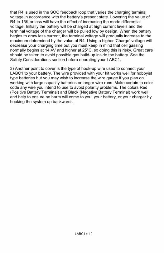
LABC1 • 19
that R4 is used in the SOC feedback loop that varies the charging terminal voltage in accordance with the battery’s present state. Lowering the value of R4 to 15K or less will have the effect of increasing the mode differential voltage. Initially the battery will be charged at high current levels and the terminal voltage of the charger will be pulled low by design. When the battery begins to draw less current, the terminal voltage will gradually increase to the maximum determined by the value of R4. Using a higher ‘Charge’ voltage will decrease your charging time but you must keep in mind that cell gassing normally begins at 14.4V and higher at 25°C, so doing this is risky. Great care should be taken to avoid possible gas build-up inside the battery. See the Safety Considerations section before operating your LABC1.
3) Another point to cover is the type of hook-up wire used to connect your LABC1 to your battery. The wire provided with your kit works well for hobbyist type batteries but you may wish to increase the wire gauge if you plan on working with large capacity batteries or longer wire runs. Make certain to color code any wire you intend to use to avoid polarity problems. The colors Red (Positive Battery Terminal) and Black (Negative Battery Terminal) work well and help to ensure no harm will come to you, your battery, or your charger by hooking the system up backwards.

LABC1 • 20
TROUBLESHOOTING GUIDE
If your LABC1 does not work correctly after construction, recheck the following:
• correct orientation of VR1, and U1 (see PC board layout diagram)
• correct polarity of electrolytic capacitors
• correct orientation of diodes D1 to D17
• correct orientation of transistor Q1
• No shorted traces on the bottom side of the circuit board
• all solder connections.
Hints
• Erratic or unstable operation is generally caused by faulty solder joints or cable connections.
Replacement components may be ordered directly from Ramsey Electronics, Inc. but records show that failure rates for these parts are extremely low. Please understand that it is nearly impossible to “troubleshoot” by phone. Any specific questions should be documented and sent to us by email or snail-mail. Email questions should be sent to [email protected].

LABC1 • 21
CONCLUSION We sincerely hope that you enjoy the use of this Ramsey product. As always, we have tried to compose our manual in the easiest, most user-friendly format that is possible. As our customers, we value your opinions, comments, and additions that you would like to see in future publications. Please submit comments or ideas to: Ramsey Electronics Inc. Attn. Hobby Kit Department 590 Fishers Station Drive Victor, NY 14564 Please feel free to visit our Website at www.ramseyelectronics.com and offer your observations to other kit enthusiasts as well. And once again, thanks from the folks at Ramsey!

LABC1 • 22
This page intentionally left blank. Don’t you hate it when people do this? Why don’t they just admit that they ran out of things to say!
LABC1 • 23
The Ramsey Kit Warranty Please read carefully BEFORE calling or writing in about your kit. Most problems can be solved without contacting the factory. Notice that this is not a "fine print" warranty. We want you to understand your rights and ours too! All Ramsey kits will work if assembled properly. The very fact that your kit includes this new manual is your assurance that a team of knowledgeable people have field-tested several "copies" of this kit straight from the Ramsey Inventory. If you need help, please read through your manual carefully. All information required to properly build and test your kit is contained within the pages! 1. DEFECTIVE PARTS: It's always easy to blame a part for a problem in your kit, Before you conclude that a part may be bad, thoroughly check your work. Today's semiconductors and passive components have reached incredibly high reliability levels, and it’s sad to say that our human construction skills have not! But on rare occasions a sour component can slip through. All our kit parts carry the Ramsey Electronics Warranty that they are free from defects for a full ninety (90) days from the date of purchase. Defective parts will be replaced promptly at our expense. If you suspect any part to be defective, please mail it to our factory for testing and replacement. Please send only the defective part(s), not the entire kit. The part(s) MUST be returned to us in suitable condition for testing. Please be aware that testing can usually determine if the part was truly defective or damaged by assembly or usage. Don't be afraid of telling us that you 'blew-it', we're all human and in most cases, replacement parts are very reasonably priced. 2. MISSING PARTS: Before assuming a part value is incorrect, check the parts listing carefully to see if it is a critical value such as a specific coil or IC, or whether a RANGE of values is suitable (such as "100 to 500 uF"). Often times, common sense will solve a mysterious missing part problem. If you're missing five 10K ohm resistors and received five extra 1K resistors, you can pretty much be assured that the '1K ohm' resistors are actually the 'missing' 10 K parts ("Hum-m-m, I guess the 'red' band really does look orange!") Ramsey Electronics project kits are packed with pride in the USA. If you believe we packed an incorrect part or omitted a part clearly indicated in your assembly manual as supplied with the basic kit by Ramsey, please write or call us with information on the part you need and proof of kit purchase. 3. FACTORY REPAIR OF ASSEMBLED KITS: To qualify for Ramsey Electronics factory repair, kits MUST: 1. NOT be assembled with acid core solder or flux. 2. NOT be modified in any manner. 3. BE returned in fully-assembled form, not partially assembled. 4. BE accompanied by the proper repair fee. No repair will be undertaken until we have received
the MINIMUM repair fee (1/2 hour labor) of $25.00, or authorization to charge it to your credit card account.
5. INCLUDE a description of the problem and legible return address. DO NOT send a separate letter; include all correspondence with the unit. Please do not include your own hardware such as non-Ramsey cabinets, knobs, cables, external battery packs and the like. Ramsey Electronics, Inc., reserves the right to refuse repair on ANY item in which we find excessive problems or damage due to construction methods. To assist customers in such situations, Ramsey Electronics, Inc., reserves the right to solve their needs on a case-by-case basis.
The repair is $50.00 per hour, regardless of the cost of the kit. Please understand that our technicians are not volunteers and that set-up, testing, diagnosis, repair and repacking and paperwork can take nearly an hour of paid employee time on even a simple kit. Of course, if we find that a part was defective in manufacture, there will be no charge to repair your kit (But please realize that our technicians know the difference between a defective part and parts burned out or damaged through improper use or assembly). 4. REFUNDS: You are given ten (10) days to examine our products. If you are not satisfied, you may return your unassembled kit with all the parts and instructions and proof of purchase to the factory for a full refund. The return package should be packed securely. Insurance is recommended. Please do not cause needless delays, read all information carefully.

LABC1 • 24
Price: $5.00 Ramsey Publication No. MLABC1 Assembly and Instruction manual for: RAMSEY MODEL NO. LABC1
RAMSEY ELECTRONICS, INC. 590 Fishers Station Drive Victor, New York 14564 Phone (585) 924-4560 Fax (585) 924-4555 www.ramseyelectronics.com
REQUIRED TOOLS • Soldering Iron Ramsey WLC-100, • Thin Rosin Core Solder Ramsey RTS12 • Needle Nose Pliers Ramsey RTS05 • Small Diagonal Cutters Ramsey RTS04 <OR> Complete Soldering Tool Set RS64-2801 ADDITIONAL SUGGESTED ITEMS • Optivisor Magnifier Headband Ramsey OPMAG • Holder for PC Board/Parts Ramsey RTS13, • Desoldering Braid Ramsey RTS08
LABC1 LEAD ACID BATTERY CHARGER KIT Quick Reference Page Guide
Quick Battery Theory ....................... 4 Circuit description ............................ 6 Schematic diagram .......................... 8 Parts layout Diagram ....................... 9 Parts list ........................................... 10 Kit Assembly .................................... 12 Troubleshooting guide ..................... 19 Warranty .......................................... 23
TOTAL SOLDER POINTS 90
ESTIMATED ASSEMBLY
TIME Beginner ........... 2 hrs Intermediate .........1.5 hrs Advanced .............1 hr