lEA COAL RESEARO-i
83
lEA COAL RESEARO-i
Transcript of lEA COAL RESEARO-i

lEA COAL RESEARO-i

Coal gasification for IGCC power generation
Toshi'ichi Takematsu Chris Maude
IEACR/37 March 1991 lEA Coal Research, London

Copyright © IEA Coal Research 1991
ISBN 92-9029-190-7
This report, produced by IEA Coal Research, has been reviewed in draft form by nominated experts in member countries and their comments have been taken into consideration. It has been approved for distribution by the Executive Committee of IEA Coal Research.
Whilst every effort has been made to ensure the accuracy of information contained in this report, neither IEA Coal Research nor any of its employees nor any supporting country or organisation, nor any contractor of IEA Coal Research makes any warranty, expressed or implied, or assumes any liability or responsibility for the accuracy, completeness or usefulness of any information, apparatus, product or process disclosed, or represents that its use would not infringe privately-owned rights.

lEA Coal Research
lEA Coal Research was established in 1975 under the auspices of the International Energy Agency (lEA) and is currently supported by fourteen countries (Australia, Austria, Belgium, Canada, Denmark, the Federal Republic of Germany, Finland, Italy, Japan, the Netherlands, Spain, Sweden, the UK and the USA) and the Commission of the European Communities.
lEA Coal Research provides information and analysis of all aspects of coal production and use, including:
supply, transport and markets; coal science; coal utilisation; coal and the environment.
lEA Coal Research produces:
periodicals including Coal abstracts, a monthly current awareness journal giving details of the most recent and relevant items from the world's literature on coal, and Coal calendar, a comprehensive descriptive calendar of recently-held and forthcoming meetings of interest to the coal industry; technical assessments and economic reports on specific topics throughout the coal chain; bibliographic databases on coal technology, coal research projects and forthcoming events, and numerical databanks on reserves and resources, coal ports and coal-fired power stations.
General enquiries about lEA Coal Research should be addressed to:
Mr John Trubshaw Head of Service lEA Coal Research Gemini House 10-18 Putney Hill London SW15 6AA United Kingdom
Telephone: 081-7802111 Telex: 917624 Fax: 081-780 1746
3

Abstract
Concern for environmental issues has generated increasing interest in new technologies for coal utilisation which offer increased efficiency with reduced emissions. Coal gasification is a well established technology for the production of pipeline gas or synthesis gas for chemicals production. In both cases, attention has been given to processing of the raw gas to remove particulates, sulphur compounds and other impurities. Efforts have been made to take advantage of these proven commercial scale systems and to adapt them to coal conversion for electric power generation.
This report reviews the various gasification processes that have been developed and makes an assessment of their readiness for application in utility service. A simplified technique for comparative analysis of different schemes is presented, which introduces the concept of heat by-pass. Attention is drawn to various facets of the process where additional development could be expected to result in increased plant efficiency, with particular emphasis on hot gas cleaning. A brief survey shows that more than twenty countries have active programmes aimed at furthering development of IGCC applications, including several with plans for full-scale demonstration plants.
4

Contents
List of figures 7
List of tables 9
Acronyms and abbreviations 11
1 Introduction 13
2 IGCC power generation 15 2.1 Advantages 15
2.1.1 Gaseous emissions 16 2.1.2 Solid residues 16 2.1.3 Water consumption 17 2.1.4 Phased construction 18
2.2 Operating efficiency 19 2.3 Demonstration plants 21
2.3.1 LUnen 21 2.3.2 Cool Water 23 2.3.3 Plaquemine 24
3 Coal gasification technologies 26 3.1 Coal characteristics 26
3.1.1 Reactivity and volatile matter 26 3.1.2 Caking and swelling 26 3.1.3 Fixed carbon 26 3.1.4 Ash characteristics 26 3.1.5 Particle size distribution 27 3.1.6 Preferred coal characteristics 27
3.2 Development of coal gasification 27 3.2.1 First generation gasifiers 28 3.2.2 Second generation gasifiers 28
3.3 Process characteristics for efficient gasification 31 3.3.1 High temperature 31 3.3.2 Size and scale-up considerations 33 3.3.3 Load following capability 34 3.3.4 Coal feed systems 36
5

3.3.5 Oxidant 37 3.3.6 Gas cleanup 39
3.4 Comparison of processes 41 3.4.1 Moving bed gasifier 42 3.4.2 Fluidised bed gasifiers 42 3.4.3 Entrained flow gasifiers 44
3.5 Evaluation of selected gasifiers 45
4 Status of hot dry gas cleaning technologies 46 4.1 Dust removal systems 46
4.1.1 Electrostatic precipitators 46 4.1.2 Moving granular collectors 48 4.1.3 Rigid ceramic filters 49 4.1.4 Ceramic fabric filters 50 4.1.5 Ceramic fibre filters 51 4.1.6 Metallic felt filters 52 4.1.7 Comparison of filter systems 53
4.2 Desulphurisation 54 4.2.1 Development of zinc ferrite sorbents 55 4.2.2 Other metal oxide sorbents 56 4.2.3 Prospects for commercial application 61
4.3 Ammonia removal 62 4.4 Alkali removal 63
5 Status of development 65 5.1 Australia 65 5.2 Austria 65 5.3 Belgium 65 5.4 Brazil 65 5.5 Canada 66 5.6 China 66 5.7 Czechoslovakia 67 5.8 Denmark 67 5.9 Finland 67 5.10 France 67 5.11 Germany 67 5.12 India 68 5.13 Italy 69 5.14 Japan 69 5.15 Netherlands 69 5.16 Portugal 70 5.17 South Africa 70 5.18 Spain 70 5.19 Sweden 70 5.20 United Kingdom 70 5.21 United States of America 71 5.22 Other countries 72 5.23 Commentary 72
6 Conclusions 73
Appendix: Status of demonstration and commercial plants 75
References 76
6

5
10
15
20
25
Figures
IGCC concept 15
2 Comparison of residues 17
3 Sankey diagram 19
4 Effect of fuel conversion efficiency 20
Effect of heat by-pass 2/
6 Liinen flowsheet 22
7 Cool Water flowsheet 23
8 Plaquemine flowsheet 24
9 Concept of a coal gasification system 27
Corrosion resistance of water cooled refractories 32
11 Slag penetration of refractories 32
12 Load variation at the HTW demonstration plant 35
13 Illinois No 6 load following test 35
14 PRENFLO - response to load change 36
PRENFLO -load change rate 36
16 IGCC efficiency dependency on gasification efficiency 37
17 Effect of moisture in coal on gasification efficiency 38
18 Gas composition versus gas temperature 43
19 Pilot-scale filters treating gasifier or PFBC gas 47
Tube-type precipitator 48
21 Kawasaki granular bed filter 48
22 Ceramic cross flow filter element 49
23 Cross-flow filter system 49
24 Pilot-scale candle filter module at Grimethorpe 50
Regimes of measured pressure drop and collection efficiency 52
26 Clean gas concentrations as a function of face velocities for various filter systems 52
7

27 Fuel gas desulphurisation 54
28 Zinc ferrite sulphidation - laboratory-scale tests 55
29 Zinc ferrite sulphidation - laboratory-scale tests 55
30 AMAX sorbent sulphidation 56
31 S02 stack emission 56
32 Desulphurisation - lOT mixed metal oxide process 57
33 Regeneration - lOT mixed metal oxide process 57
34 TOR screening of sorbents 58
35 Effect of organic binder content 58
36 Honeycomb type sulphur sorbent 59
37 H2S concentration as a function of on-stream time 59
38 Example of series test results - hot gas cleaning 60
39 H2S content in off-gas during sulphidation (Cu in alumina system) 60
40 S02 content in off-gas during regeneration (Cu in alumina system) 60
41 Typical H2S breakthrough curve - Delft system 61
42 Sulphur captured at breakthrough as a function of time - Delft system 61
43 Conversion of NH3 by a NijMg.A1203 catalyst at 800°C 63
44 Conversion of NH3 by Ir-promoted Ni catalyst 63
8

5
10
15
20
25
Tables
Emissions and solid wastes from coal-based power plants 16
2 Cool Water stack emissions 16
3 Leachate composition (in mgA) from the EPA-EP, SWG and ASTM short-term leaching tests 18
4 Comparison of the three rGCC plants 21
Cool Water capability factors 23
6 Operating statistics of Plaquemine plant 25
7 Preferred sizes and types of coal for various types of gasifiers 27
8 Classification of various second generation gasifiers 29
9 Comparison of gasifier performance 33
Coal properties 34
11 Oxygen consumption and cold gas efficiency 34
12 Gasifier load and carbon conversion at Cool Water 36
13 Comparison of 'dry' and 'wet' feed systems: gasification data 37
14 Comparison of 'dry' and 'wet' feed systems: net plant efficiency 38
Selected gasifier characteristics 38
16 Plant performance summary for coal throughput of 240 t/h 38
17 Comparison of system capital cost estimates for coal throughput of 240 t/h 39
18 Typical limits of impurities in the fuel gas for gas turbines 40
19 Types and typical gasification conditions of selected gasifiers 41
Typical performance of the selected gasifiers 41
21 Evaluation of selected gasifiers 45
22 Particulate emission limits 46
23 Test results for ESPs at elevated temperatures 47
24 Summary of candle operating characteristics over 2000 cycles 50
Summary of candle performance 51
26 Summary of performance of recent HTHP bag filter tests 51
.~-- ------- -----~---..~-._------~~~.----._-~_.
9

27 Description of test dust for ceramic fibre filters 51
28 Summary of test results for ceramic fibre filters 52
29 Summary of filter tests 53
30 Test conditions and main results for filter systems 53
31 PDU desulphurisation performance summary 56
32 PDU regeneration performance data 56
33 Properties of CuO.Ah03 sorbents 59
34 Chemical composition of manganese nodules and red mud 61
35 Performance of absorbents at 800a C 61
36 Composition of simulated coal gas in screening tests 63
37 Summary of fixed-bed alkali capture tests 64
10

Acronyms and abbreviations
AFBC BET CFB CWCGP daf DCF EPA-EP ESP FGD GCC GHSV GPGA GSCU GSP HHV HRSG HTHP HTW i.d. IGCC KRW LHV maf MIP NSPS O&M pc PCF PFBC PDU PRENFLO SCGP RCRA SGW SNG SSMS STP SUFCO TCGP
Atmospheric fluidised bed combustion Brunauer Emmett Teller method for pore surface measurement Circulating fluidised bed Cool Water coal gasification project dry and ash free discounted cash-flow Environmental Protection Agency - extraction proceedure Electro-static precipitator flue gas desulphurisation gasification combined cycle gas hourly space velocity Great Plains Gasification Associates gas stream clean-up Gaskombinat Schwarze Pumpe higher heating value heat recovery steam generator high temperature and high pressure high temperature winkler inside diametre intergrated gasification combined cycle Kellogg-Rust-Westinghouse lower heating value moisture and ash free Molten Iron Pure-gas New Source Performance Standards operation and maintenance pulverised coal pulverised coal firing pressurised fluidised-bed combustion process development unit pressurised entrained flow gasification Shell coal gasification processes Resource Conservation and Recovery Act synthetic groundwater substitute natural gas solid-supported molten salt standard temperature and pressure Southern Utah Fuel Company Texaco coal gasification process
11

TGA thermo-gravimetric analysis TGR thermo-gravimetric reactor YEW Vereinigte Elektrizitatswerke wg water gauge WHRSG waste heat recovery steam generator
Representative public organisations ASTM American Society for Testing and Materials ANL Argonne National Laboratory of the USA CANMET Canada Centre for Metallurgy and Energy Technologies CMRC Coal Mining Research Centre of Japan CRE Coal Research Establishment of the UK CRIEPI Central Research Institute of Electric Power Industry of Japan DOE Department of Energy of the USA EPA Enviromental Protection Agency of the USA EPRI Electric Power Research Institute of the USA IGT Institute of Gas Technology of the USA KEMA Research Institute of the Electricity Companies of the Netherlands METC Morgantown Energy Technology Centre of the USA MIT Massachusetts Institute of Technology of the USA MIT! Ministry of International Trade and Industry of Japan NEDO New Energy and Industrial Technology Development Organisation in Japan NYU New York University SEP Samemwerkende Electriciteits - Productiebedrijven NV STEAG Steinkohlen ElektriziUits AG
12

1 Introduction
This report specifically reviews the various coal gasification technologies that may be applicable for IGCC power generation and indicates potential development areas in which performance improvements might be made.
Coal accounts for about 72% of all fossil fuels. This fact implies that coal will provide a major source of energy in the future irrespective of the prevailing oil price. Consequently, it is of vital importance to create and develop the most effective technologies to utilise coal as an independent source of energy, carbon or hydrogen.
Despite the fluctuations in the price and availability of oil since 1973, the worldwide use of coal has been increasing at the rate of about 3% per year. In the period 1976-86 the overall increase was 29% (British Petroleum, 1987).
The electric utility industry in particular makes extensive use of coal fired power plants in many parts of the world. For example, in the US about 45% of electricity production is based on coal (Voelker and Halow, 1987) while in the UK the proportion is closer to 70%. Although utilities in Japan are still largely oil based there is a noticeable progressive change of fuel from oil to coal.
Along with this increase in coal consumption in power plants, the associated increase in emissions of gaseous, liquid and solid wastes has given rise to some concern, especially as there has been a growing public awareness of environmental issues. Since coal-based electricity generation is expected to contribute an even greater share of the electricity supply in the future (Voelker and Halow, 1987), these concerns must be addressed by development of improved technology and operating procedures.
As an example of the progress being made in this area, S02 emissions from power plants in several countries including Germany, Japan and the USA are now controlled by flue gas desulphurisation systems. Often using wet scrubbers, these
systems have been required on all new pulverised coal fired power plants in the USA whose construction began after 1978. As a result, the US electric-utility industry is operating more wet scrubber systems today than the rest of the world combined. However, these systems are costly; a new plant scrubber typically costs between $150 and $200 for each kilowatt of generating capacity.
Although it is possible to design scrubbing systems in such a way that the sulphated product is a saleable gypsum and licensing laws in Germany have encouraged this approach, it is more usual to find that scrubbers convert the undesirable gaseous emissions into a sludge waste, which must then be disposed of in an acceptable manner. A 1000 megawatt power plant that bums coal with a sulphur content of 3%, for example, could produce enough sludge in one year to cover about 80 hectare to a depth of I metre (640 acre to depth of one foot). Wet scrubbing systems also require large amounts of water, about 230 t!h for a 1000 megawatt plant (Balzhiser and Yaeger, 1987). Furthermore, these systems reduce the efficiency of electricity generation, typically, from about 36% to 32% (HHV basis, Voelker and Halow, 1987). Consequently, while this technology is acceptable today as the best available, there is a clear incentive for the development of more effective alternatives.
It is generally recognised that since the beginning of the 1960s, the pace of improvement in conventional power plant technology has been slowing down. This trend suggests that boiler/steam turbine power-plant designs have approached practical limitations set by the laws of thermodynamics and the properties of the materials of construction (Hirato, 1987; Balzhiser and Yaeger, 1987). However, improvements in industrial gas turbines and significant increases in the available unit size of these machines have opened up alternative lines of development. Combined cycle systems, using both gas and steam turbines offer significant increases in station efficiency. Integration with chemical process technology, adapted from other applications, opens up a
13

Introduction
number of possible routes for coal utilisation, which are all capable of meeting very stringent environmental standards. An important example of this approach is the Integrated Gasification Combined Cycle (IGCC) power generation system.
The successful operation of the Cool Water facility, an IGCC power plant demonstration unit based on the Texaco
gasification process, has shown the technical viability and environmental superiority of the IGCC system for power generation. The operating experience and results obtained from this facility will provide a firm foundation for development of full commercial applications of the IGCC system to satisfy particular requirements of individual utilities.
14

2 IGCC power generation
A promising technology for power generation which is expected to contribute a considerable share of electricity supply by the year 2000 and beyond is the combined cycle system (Mizutani, 1986) in which gas turbines and steam turbines are used in combination.
Combined cycle power generation, firing natural gas, is now becoming popular because of its high efficiency and minimal environmental impact. While natural gas fired combined cycle is almost ideal for power generation systems, the worldwide resources of natural gas are limited and far smaller than those of coal. Consequently, the low price of natural gas relative to coal, experienced in 1988-89, is unlikely to be sustained, especially if changes to energy legislation that are now proposed both in Europe and the USA do result in significant use of natural gas for utility power production. For this reason, combined cycle firing with gas made from coal has attracted world attention as a logical development step for natural gas fired combined cycle systems.
Since the availability of natural gas for utility power generation might decline within the service life of any plants constructed in the near future, with consequent price escalation, utilities now tend to include provision for possible conversion to coal gas firing, at some future date, in their planning for new combined cycle plants. To proceed with confidence, they need assurance that reliable, cost effective gasification systems will be available when required.
A simple concept of a coal based IGCC power generation system is shown in Figure 1. Fuel gas is generated in the gasifier and purified in the gas cleanup system. Clean gas is sent to the gas turbine where it is burned with compressed air to provide a stream of hot, high pressure gas which drives the turbine to generate electricity. The exhaust gases from the turbine pass to a waste heat boiler where steam at high pressure and temperature is raised by heat exchange with boiler feed water. This steam then passes to the steam turbine which generates additional electricity.
ash sulphur
Figure 1 IGCC concept
Such a system is described as operating on the waste heat recovery cycle, in which the gas turbine contributes about 60% of the total power output. It is generally recognised that this cycle is most desirable for power generation because it has the least complexity. As development of heavy industrial gas turbines proceeds, including the use of cooled blades in the high temperature regions of the expansion turbine, maximum cycle temperatures are being increased. This raises the efficiency of the gas turbine itself and, by reason of the fact that corresponding exhaust gas temperatures also increase. enables more advanced conditions to be adopted for the steam cycle without supplementary firing. These efficiency improvements mean that the waste heat recovery cycle is becoming increasingly more attractive (Hozumi, 1986a).
2.1 Advantages In comparison with pulverised coal fired (PCF) power generation, which does not employ a combined cycle, an IGCC system does have an initial penalty associated with conversion of the coal into fuel gas. However, the high
15

IGCC power generation
efficiency downstream that is obtainable from the combined cycle can more than offset this disadvantage. Beside high efficiency, IGCC has a number of other advantages over PCF systems as follows:
excellent environmental performance: smaller quantity of solid residue; lower water consumption; capability of phased construction.
2.1.1 Gaseous emissions
An important advantage of the IGCC system is provided by the gas cleanup stage. A wide range of gas treatment processes is available from other applications, many of which are capable of delivering fuel gas with extremely low levels of undesirable constituents such as sulphur compounds. rGCC systems therefore offer the greatest ability to meet stringent environmental emission limits. At present, the majority of proven gas purification processes employ either aqueous solutions or low boiling organic reagents for gas scrubbing, which can only accept gas for processing at relatively low temperature. Consequently, until high temperature, dry, alternative gas processing techniques can be introduced commercially, there are penalties in terms of plant complexity and overall thermal efficiency arising from the necessity for gas cooling and unavoidable heat losses from the system.
Under the reducing conditions found in any gasifier, the sulphur in the coal is mostly converted into hydrogen sulphide (H2S) rather than sulphur dioxide (S02). The H2S in the raw gas can easily be removed to extremely low levels, over 99% sulphur recovery, by wet scrubbers (Cornett, 1987; Rothfeld, 1988). The liquid sorbents can be regenerated in processes which ultimately release the sulphur in elemental form. This material is quite pure and therefore a saleable commodity.
Similarly, nitrogen from the coal may be converted into ammonia (NH3), which readily dissolves in water and is removed in the course of gas scrubbing. More difficult may be the formation of carbon disulphide (CS2) and carbon oxysulphide (COS) which are less readily removed from the gas and may adversely affect H2S removal. Any fine solid materials carried over from the gasifier in the product gas can also be removed almost completely in systems which use dry cyclones and/or water scrubbers.
Since the majority of both the sulphur and nitrogen found in the raw coal is removed in the gas cleaning stage, prior to combustion, undesirable gaseous emissions from the power generation stage of the plant, in the final flue gas, can be quite low. Table I shows the comparison of S02 and NOx
emissions and solid residues produced by pulverised coal firing with flue gas desulphurisation (PCF+FGD), atmospheric fluidised bed combustion (AFBC) and by the integrated gasification combined cycle (IGCC).
While S02 in all three systems is produced only from sulphur in the fuel that is not otherwise trapped in the process, NOx
is produced from nitrogen contained both in the fuel and
16
Table 1 Emissions and solid wastes from coal·based power plants, Illinois coal, 3.5% sulphur (t/y.MW dry) (Rothfeld, 1988)
Emissions Solid S02 NO, wastes
PCF+ FGD 13 7 680 AFBC 6 4 1090 IGCC 4 3 270
combustion air. In the IGCC case, however, fuel nitrogen is trapped as ammonia, as described above, so that NO, in this system is generated mainly from nitrogen contained in the air supplied to the combustion chamber of the gas turbine. Careful attention to the combustion process, using such means as staged combustion, steam, or water injection, enable NO, emissions from this cause to be further controlled.
In Table 2. a comparison of actual performance test results obtained from the Cool Water plant with both the plant permit limits and the general US EPA New Source Performance Standards (NSPS) is shown. This shows that the typical emissions from this demonstration plant, for S02, NOx, CO and particulate matter, reach only 10-20% of allowable limits and are much lower than specifications established by the NSPS.
Table 2 Cool Water stack emissions - ng/J (Watts and others, 1987)
SUFCo Pitts No 8 Permit* 1985 III No 6 source Federal limit EPA test EPA test test NSPSt
S02 high S 70 nla 29.2 52.5 258 low S 14 7.7 nla nla 103t
NO, 56 30.1 40.4 28.4 258 CO 30 1.7 1.7 <0.9 nls Particulate 4 0.4 3.9 3.9 13 matter
* permit and regulatory limit t New Source Performance Standards for a coal-fired power plant
burning equivalent coal ::: 344 ng/J uncontrolled emissions or 13 ng/J controlled emissions nla not applicable nls no standard
2.1.2 Solid residues
Table I also shows that the IGCC system will produce less total solid residue than either the PCF+FGD or AFBC alternatives. These figures include all solid products including ash, gypsum or elemental sulphur, depending on the process being considered. Figure 2 shows a comparison of the amounts of the residues between ;.1 typical IGCC plant and a PCF+FGD plant where each system is based on the same electricity generating capacity, 2000 MWe (Lacey, 1988).
The quantity of coal fed to the IGCC plant is expected to be about 8% less than that for the PCF plant, while the amount

IGCC power generation
input, l/y output, l/y
power
steamturbine
gas turbine '--_J-l--------
recovery steam generator
gas purificati0:f}- -.-[2,.
gasification sulphur 72,000
I--------~
A e ash 970,000L2blimestone
air separation 634,000 unit
coal 6,065,000
a 2000 MWe coal gasification combined cycle
Figure 2 Comparison of residues (Lacey, 1988)
of solid residue produced by the IGCC plant, exclusive of sulphur, is expected to be only about 60% of that from the PCF plant. Sulphur can be considered separately because it is produced as pure elemental sulphur which is a saleable by-product. Although gypsum produced by the flue gas desulphurisation system in the PCF plant could be used for building materials, and such use is on the increase, much of it is disposed of to landfill at present. IGCC, therefore offers a much reduced rate of usage of available landfill.
In many of the gasifier systems currently under consideration for IGCC applications, the majority of the mineral matter from the raw coal, usually called ash, is melted and rejected as vitreous material. Small amounts of fly ash may be produced which, not having been fused, do require careful handling for disposal. The vitrified material, however, is almost totally impervious to groundwater and resistant to natural leaching in a landfill. This material may also be suitable for ground stabilisation or other applications in the construction industry.
Results from various leaching tests carried out on the ash obtained from various gasifiers are given in Table 3, These tests were performed by Hassett and others (1985) using ash obtained from dry ash moving bed gasifiers of Wellman Galusha, Lurgi and METC types. The tests were carried out in accordance with standard procedures as defined by the Environmental Protection Agency Extraction Procedure (EPA-EP), a variation of this test using a synthetic groundwater (SGW), and the American Society for Testing and Materials (ASTM). As can be seen from Table 3, none of the leachates obtained by the EPA-EP method showed results in excess of the EP Trigger values which define
output. l/yinput, t/y
limestone gypsum 320,000 500,000
/\LJ. -~ (J ~-(J
sulphuric acid calcium chloride 25,000 60,000
L....,.<:....-....Y .....a__--==--~~~~~~~:::_p_o_w_er_ash 1,051,000
coal 6,570,000
b 2000 MWe conventional power station with FGD
hazardOUS waste under the Resource Conservation and Recovery Act (RCRA) criteria.
2.1.3 Water consumption
A substantial amount of water is required for day to day operation of a conventional PCF power plant. For example, it can be shown that a 1000 MWe station will require approximately 5000 t/h of make-up water for the cooling system, to replace evaporation and other losses from the cooling towers. In cases where a flue gas desulphurisation system is incorporated, a further 230 t/h of feed water may be required by the FGD scrubbers.
In contrast, the water requirements for a combined cycle plant are much less, since as much as two-thirds of the total power produced may be generated by the gas turbine system, which has no steam to condense and so needs no cooling water (Balzhiser and Yaeger, 1987). This advantage applies equally in the IGCC system which, in addition, does not employ FGD for sulphur control and so, avoids the need for scrubber make-up water there too.
The Cool Water demonstration plant used a Selexol system for sulphur removal, which operated at about 40°C and did, therefore, require some cooling water. It also used a water slurry system (60% coal, 40% water) for coal feeding. Consequently this plant had a greater water consumption than could be expected for other types of IGCC systems. Despite these requirements, it was reported that the water usage at Cool Water was approximately 70% of that required by a comparable conventional PCF plant using FGD scrubbing (Watts and others, 1987).
17

-------------------------------
------
IGCC power generation
Table 3 Leachate composition (in mg/I) from the EPA-EP, SWG and ASTM short-term leaching tests (Hassett and others, 1985)
Great Plains Gasification Associates ash samples (Lurgi) RCRA W-G METC-2 G-l G-2 G-3 G-4D G-4W G-5 mean limit
Si EPA-EP SGW ASTM 4
91 43 47
26 76 29
29 7
99 6.5 13
61 26
78 43
64 34 23
Al EPA-EP SGW ASTM 89
7 0.9 5.2
0.7 6.2 68
0.7 1.2
2.1 506
5.8 210 1200
<0.03 65
<0.03 15 115
341
Ca EPA-EP SGW ASTM 130
1055 2.8 4.5
1010 11.6 39
1140 12
951 9.2
915 13 17
760 8.1
1000 8.5
976 9.3 48
Mg EPA-EP SGW ASTM 0.09
86 0.46 0.4
43 1.62 1.8
204 1.48
141 <0.02
137 0.98 0.89
160 0.15
180 0.1
136
0.80
Na EPA-EP SGW* ASTM 3300
520 853 1000
1090 1141 1952
1000 1180
1177 1719
834 1181 3130
1800 2100
1400 1700
1117 1411 2346
K EPA-EP SGW ASTM 150
12 24L 50
7 10 52
50 42
38 41
24 22 95
31 28
44 43
29 27 87
S04t EPA-EP SGW
280 628
524 1123
200 623
793 1179
441 872
448 885
As EPA-EP SGW ASTM 0.30
0.02 0.17 0.80
0.Q7 0.14 1.10
0.10 0.31
0.01 0.28
0.01 0.37 0.86
0.14 0.49
0.06 0.56
0.06 0.33 0.77
5
Ba EPA-EP SGW ASTM 0.28
1.94 0.11 0.14
3.50 0.14 0.37
2.29 0.10
0.55 0.08
0.97 0.18 0.19
1.40 0.09
0.88 0.03
1.65 0.10 0.25
100
Sc EPA-EP SGW ASTM <1
0.011 <0.002
0.008 <0.002
0.011 0.014
0.003 0.010 0.012
0.016 0.024
0.023 0.063
0.012 0.020
1.0
H EPA-EP SGW ASTM 27
10 6.8 15
21 10 24
15 8.7
12 5.5
9.7 4.2 7.9
19 14
16 14
15 0.9 19
Other RCA elements: Cd (limit 1.0): <0.1 in all tests: Cr (limit 5.0): <0.1 in all tests Pb (limit 5.0): <0.2 in all tests: Hg (limit 0.2): <0.0003 in all tests
Other elements: Fe:<5 in all tests: Cu <0.03 in all tests: Ni: <0.1 in all tests Mn: <2.0 in EPA-EP and <0.05 in all SGW and ASTM tests Sr: mean of 30 in EPA-EP and <0.7 in all SGW and ASTM tests Mo: <0.3 in EPA-EP and SGW and <0.6 in ASTM tests
* The synthetic groundwater leachant contains 436 mg/L Na t The synthetic groundwater leachant contains 338 mg/L S04
2.1.4 Phased construction might be provided by gas turbines, which could take advantage of low natural gas or distillate fuel prices, during
Because it is inherently modular in design, an IGCC plant the early years of plant operation. can be constructed in phases, thus allowing generating capacity and/or fuel use capability to be built up in As electricity demand grows, addition of waste-heat boiler
increments. Such flexibility in construction minimises the and steam turbine modules would provide an increase not
investment risks associated with uncertainties in the growth only in the capacity of the plant but also in operating
of the electricity demand and in fuel price fluctuations. In a efficiency. Ultimately, when fuel price considerations make it
typical installation, the first increment of generating capacity economical to do so, a coal gasification facility could be
18

IGCC power generation
installed at the plant site to facilitate fuel conversion to coal in an environmentally acceptable manner (Balzhiser and Yaeger, 1987).
Since many of the modules can be factory assembled and skid mounted, on-site construction time, which is frequently costly, may be minimised. Consequently, this possibility of phased installation is an important feature of rGee based power generation which offers utility planners a degree of flexibility that has not been available previously.
2.2 Operating efficiency The major energy flows through a typical rGee system are shown in the Sankey diagram given in Figure 3. This shows that the three major elements in the process are conversion of the incoming coal into a clean fuel gas, followed by the gas turbine and then the steam turbine system. There are two other, less obvious but equally important, elements which may be described as the heat by-pass ratio and generation efficiency. The performance of a wide range of power generating systems can be evaluated and compared in terms of these five elements, whose interrelationship may be expressed by the following equation (Maude, 1974):
Esys =Econ x [Egt(1-Esc)(1-Hbp) + Esc] x Egen (1)
where: Esys =overall efficiency of the rGee system
energy input
10r
Econ =fuel conversion efficiency Egt = gas turbine cycle efficiency Esc = steam cycle efficiency Hbp =heat by-pass ratio (O<Hbp<l) Egen =generation efficiency
The overall efficiency of the system, Esys, is largely self-explanatory and denotes the overall efficiency with which potential energy recovered from the fuel is converted into saleable product electricity, after deduction of any power required to operate the system.
Fuel conversion efficiency, Econ, represents the efficiency with which the potential energy recovered from the fuel is converted into usable energy for further conversion in the two power generating elements. Both gasification and gas cleaning are included in this term. For a system burning natural gas, where no gas cleaning is required, this value would normally be 100% or very close to it. Whereas in a gasification system including wet gas cleaning, sulphur recovery and significant unrecoverable losses from the gas making train, it might be as low as 90% or less.
Gas turbine cycle efficiency, Egt, represents the efficiency with which potential energy recovered from the fuel and delivered specifically to the gas turbine is converted into shaft power. It also implies that all waste heat from the gas turbine becomes available for steam raising.
39.1% net energy output
GAS TURBINE
I
I ~
~V;\J~ ,GAS /1
CLEANING /lV/ / /~
6.7%
FUEL CONVERSION
l-~-----r-:7'!f;Z--;~--.---~
heat by-pass = fuel energy used directly by the steam cycle overall system efficiency = 39.1 %
Figure 3 Sankey diagram
19
IGCC power generation
The efficiency of the steam cycle, Esc, refers to the overall efficiency of the complete steam cycle system, including steam raising efficiency of the waste heat boilers and other heat exchangers, together with performance of the turbine itself - in short it is the efficiency with which all the energy supplied to the steam system is converted into shaft power.
The term heat by-pass ratio, Hbp, is used to account for that proportion of the potential energy released from the fuel which does not contribute to power generation in the gas turbine. Such energy can be said to by-pass the gas turbine and be supplied directly to the steam system. For example, a conventional boiler plant, with no gas turbine component at all would be operating with 100% heat by-pass since all the heat recovered from the fuel is used for steam raising, whereas a natural gas fired combined cycle system would probably operate with zero by-pass for maximum efficiency with only the exhaust heat from the gas turbine used for steam raising.
Coal based IGCC systems usually have some form of heat by-pass inherent to their design, because of the need to recover usable heat from the gasification and gas-cleaning systems, that might otherwise go to waste. These duties are usually performed by waste heat boilers and other heat exchangers so that the recovered heat goes directly to steam raising, by-passing the gas turbine. Heat by-pass, therefore, may be an essential design feature of the fuel conversion process and typically amounts to about 20% of the energy supplied in the coal fed to the gasifier, if cold gas cleaning is also used. It should be noted also that availability of energy in the form of heat by-pass frequently influences the design, and hence efficiency, of the steam cycle. Consequently it may be difficult to identify the independent effect of heat by-pass alone, because of its close relationship to both fuel conversion and steam cycle efficiency.
The final term in the sequence is overall generation efficiency, Egen. This includes conversion efficiency from shaft power in the generators themselves but, perhaps more importantly, it is used to account for any electric power that may be consumed by the process. All power generating systems have some internal power consumption but perhaps the clearest example is in an IGCC system with an oxygen-blown gasifier. In this case there may be significant consumption of electricity by the various compressors that are required for the air separation unit for production of the essential oxygen.
This model permits performance comparison of different power generation systems in terms of the five main contributors and has the advantage that it allows the effect of individual components to be investigated as if they were truly independent variables. This facility can be used to identify areas of possible improvement in particular systems and to make initial estimates of potential rewards to be gained.
It can be shown that, as might be expected, the performance of the two power generating systems, the gas turbine and the steam cycle, have the greatest influence on overall plant performance. Much effort over many years has been devoted
to development in these areas, which are beyond the scope of this report. The other three factors, fuel conversion efficiency, heat by-pass and generation efficiency are all dependent upon the chosen processes for gasification and gas cleaning and will be discussed further.
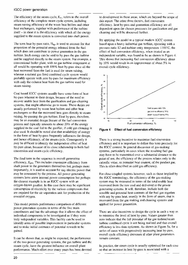
By applying the model to a typical modem IGCC system based upon a heavy industrial gas turbine, operating with a pressure ratio 12 and turbine entry temperature lIOO"C, the effect of fuel conversion efficiency, when treated as an independent variable, was found to be as shown in Figure 4. This shows that increasing fuel conversion efficiency alone by 10% would result in an improvement of about 5% in overall cycle efficiency.
50
45
<? >. 40
C " <D
~ 35 <D <D
~30
" rn CD 25 > heat by-pass ratio 10% 0
gas turbine efficiency 31 %20
steam cycle efficiency 25c/c
15
40 60 80 100
Fuel conversion efficiency, %
Figure 4 Effect of fuel conversion efficiency
There is a strong incentive to maximise fuel conversion efficiency and it is important to define this term precisely for the IGCC context. In general discussion of gas-making systems, particularly in cases where the resulting fuel gas may have to be transmitted over a substantial distance to the point of use, the efficiency of the process relates only to the calorific value, or potential heat content, of the product gas. This is often described as cold gas efficiency.
For close coupled systems however, such as those implied by the IGCC terminology, the efficiency of the gas-making system may be measured in terms of the total usable heat recovered from the raw coal and delivered to the power generating systems. It will, therefore, include both the sensible and potential heat contents of the fuel gas together with any by-pass heat, usually in the form of steam, that is recovered from the gas making and cleaning systems and applied for power generation.
There are also incentives to design the cycle in such a way as to minimise the level of heat by-pass. Values greater than zero indicate that the full potential of the gas turbine/steam turbine combined cycle is not being realised and that overall efficiency is less than optimum. As shown in Figure 5a, for a series of cases with progressively increasing heat by-pass, overall cycle efficiency decreases if other plant parameters remain constant.
In practice, the steam cycle is usually optimised for each case so that an increase in heat by-pass is associated with a
20

a Constant steam cycle efficiency
42
gasmaking efficiency 96% gas turbine efficiency 28%,
steam cycle efficiency 25%37
361~-~,~~~.~'-~~.-----'---------'--------"--"------'--'-'"-----l 15 17 19 21 23 25 27 29 31
Heat by-pass, %
b Optimised steam cycle efficiency
::1·_·. . overall system
:: ~ • gasmaking efficiency 96%
34 ~ gas turbine efficiency 28%
:: 12J +
26 ~ -"=_---'-~--- -------- steam+cycle
24 +f 22 ---t----,---------,--------,--------,--------r_-~~~~~_-~~~-
15 17 19 21 23 25 27 29 31
Heat by-pass, %
Figure 5 Effect of heat by-pass
corresponding increase in steam cycle efficiency. This effect is shown in Figure 5b, which shows that while a 7% increase in heat by-pass allows a corresponding 5% increase in steam cycle efficiency, the net effect on overall cycle efficiency is negligible.
It may be concluded, therefore, that optimisation of the steam cycle in these cases does little more than compensate for the losses in overall cycle efficiency that would otherwise result from the increase in heat by-pass. Clearly there is an advantage in designing overall system with minimum heat by-pass. The fuel gas supplied to the gas turbine should contain as much of the original heat energy from the fuel as possible, preferably in the fonn of potential heat.
Overall generation efficiency includes all allowances for internal consumption of electricity by the process. Since the objective of any power plant is to produce the maximum amount of saleable power, internal consumption should be as low as possible and generation efficiency, therefore, as high as possible.
In summary, the desirable characteristics of the three factors that are directly affected by fuel processing choices are as follows:
1 fuel conversion efficiency as high as possible; 2 heat by-pass as low as possible; 3 generation efficiency as high as possible.
Important factors affecting the efficiency of the fuel
IGCC power generation
conversion process, which are closely related to the types of gasifier, ways of feeding coal. ways of gas cleaning or kinds of oxidant to be used, are as follows:
high carbon conversion; low oxygen consumption; low steam consumption; low heat losses; high pressure and temperature gasification; low electricity consumption; increase steam cycle generation; minimise cooling of reactor walls and product gas cooling for cleanup.
2.3 Demonstration plants Three major demonstration plants encompassing complete IGCC systems on a commercial scale have been constructed to date and these are summarised in Table 4. Significant lessons have been learned from each of these, which point the way for both first commercial installations and further development of this important technology.
Table 4 Comparison of the three IGCC plants
Liinen Cool Water Plaquemine
Type of gasifier moving bed entrained flow entrained flow Ash dry ash slagging slagging Coal feed dry feed slurry feed slurry feed Oxident air-blown oxygen-blown oxygen-blown Coal throughput, tid 1700 910 2,200 HHV, MJ/kg 24.2 22.3 21.8 Carbon conversion, % 91.4 98.9 99 Product gas HHV, kJ/m3 7.8 10.6 10.2 Cold gas efficiency, % 76.3 74.3 no Combined cycle Turbine inlet temp, °C 810 1085 1090 Power output, MW 170 93 160* Overall system
efficiency, % 34.4 31 36 Net heat rate, MJ/kWh 10.5 11.5 9.99
* when all surplus steam is used for power production
2.3.1 LOnen
The first commercial scale utility operated IGCC demonstration power plant was built by Steinkohlen Elektrizitats AG (STEAG) at its Kellennann station, Ltinen, Gennany in 1972. The power generating capacity was 170 MWe. This plant was operated from 1972 to 1977 for a total of about 10,000 hours, during which the longest continuous on-stream period was about 2400 hours (Hozumi, 1986a). A diagram showing the main features of the process flow sheet is given in Figure 6. This shows that the combined cycle arrangement did not follow the simple pattern indicated in Figure 1 but incorporated a number of special features aimed at providing maximum operating efficiency.
A commercial gas turbine was adapted to allow a substantial portion of the compressor delivery air to be tapped off and
21

air intake
fresh steam 131 bar 625°C
waste heat i boiler .
air trim valve
10 bar ----
I
expansion turbine
gas cleaner
.r:-------I-
flue gas feed water preheater
IGCC power generation
pressurised coal gasification unit coupling element I combi-block
gasification steam I 20 bar 320°C
I gasification air compressor
gasification air
I 20 bar
coal gasifier
550°C
ash
Figure 6 LOnen flowsheet
passed to the gasification system. A booster compressor was provided to raise the pressure of this air to that of the gasifier. Power to drive this booster was obtained, in part, from expansion of the fuel gas prior to delivery to the combustion chambers. Air-blown Lurgi gasifiers were used and the raw gas treated in scrubbers, to remove condensables, tar and particulates. Tar was recovered and recycled to extinction in the gasifiers.
Among other firsts, was the minimum change adaptation of a commercially available large industrial gas turbine, rated at 74 MWe, to a power plant system which was specifically designed to include coal gasification. Apart from provision for the large air offtake to the gasifier and specially designed external combustion chambers, the gas turbine itself was an ordinary production machine. The standard KWU gas turbine has two silo type combustion chambers, connected to the main engine casing by short ducts. For this application, somewhat larger units were used and these featured steam generating tubes to form the flame containment in place of the more usual air cooled liner and tiles. This heat by-pass approach provided necessary cooling of the metal walls in the combustor but, perhaps more importantly, reduced the excess air in the system to maximise the electric power obtained from each kilogram of air pumped through the plant.
At this early date, the gas turbine operating conditions, turbine entry temperature and pressure (810°C, 1 MPa), were modest in comparison with current practice so that the simple waste heat cycle would not have been adequate. By placing superheat surface in the high temperature region of the combustor, heat by-pass was introduced so that necessary additional heat was put into the steam cycle to ensure high
gas turbine compressor
condenser
steam quality without the need of supplementary firing in the gas turbine exhaust.
Although the design performance was achieved, this plant experienced a number of operating difficulties, mainly arising from the wet gas cleaning system and power recovery system. This latter system was used to drive the air booster compressor placed between the gas turbine compressor and the gasifier. In particular, carry-over of liquids from the scrubbing towers caused operational problems and undue corrosion in the gas turbine (Krieb and others, 1979: Kuwabara, 1986).
According to Dorstewitz (1980), the overall system efficiency, based on gross power generation at the Lunen plant, was 36% (HHV) in a typical run using bituminous coal. In-house power consumption was estimated to be about 1.6% of the total energy input to the gasifier, according to the same author. Therefore, the net efficiency of the overall system can be estimated to be about 34.4% (HHV). Given the efficiency of available commercial gas turbines at that stage of development, this overall power generating efficiency can be regarded as an excellent performance. Important factors contributing to this result were the high thermal efficiency of the Lurgi gasifier and low in-house auxiliary power consumption required for the air-blown system.
The cold gas efficiency of the air-blown Lurgi gasifier itself, operated under pressure, is reported as 76.3% (HHV basis) (Hebden and Stroud, 1981) where the feed is a subbituminous coal of higher heating value 31.3 MJ/kg (13,450 Btu/lb) and product gas is delivered with a higher heating value of 7.8 MJ/m3. This also indicates good performance.
22

IGCC power generation
2.3.2 Cool Water
The second large scale IGCC power plant demonstration went into operation in June 1984 at the Cool Water station site in California, USA, which is owned by Southern California Edison. The power generating capacity was 117 MWe (gross), giving a net production capability of 93 MWe. Up to the end of August, 1988, the plant had accumulated over 24,000 hours of gasifier operation and generated more than 2.5 TWh. As shown in Table 5. plant capacity and on-stream factors steadily improved with increasing operating experience and the plant is reported to have met its design objectives (Watts and Dinkel, 1988).
A block diagram of the flow sheet for this plant is shown in Figure 7. The fuel gas for the gas turbine was produced in an oxygen-blown Texaco, entrained flow gasifier. Hot product gases leaving the gasifier were first cooled in waste heat boilers, to generate steam for both process and power generation duties. They then passed to water wash for particulate removal and finally through a Selexol unit for sulphur removal. The fuel gas was supplied to the combustion chamber of a commercial gas turbine (65 MWe) for power generation. A waste heat recovery steam generator (WHRSG) in the gas turbine exhaust provided further steam generating capability and superheat duty for all the steam used for power generation (55 MWe) in the bottoming steam cycle.
OXYGEN
PLANT
______ ---.J
COAL1000 Vd coal
,--~--,-I--------
COAL GASIFIER
SILO GRINDING
STORAGE
Table 5 Cool Water capability factors (Watts and Dinkel, 1988)
Year Availability, On-stream, % %
1984 35.1 43.0 1985 49.9 61.5
1986 56.7 65.9
1987 70.5 79.3
1988 90.6* 91.5"
* part year only
The plant was primarily designed to demonstrate the IGCC concept on a commercial scale at reasonable cost and, by conscious choice, did not include all the refinements necessary to achieve a high efficiency. Nevertheless, the initial operation of the Cool Water plant gave a net system efficiency of 30.5% which was equivalent to a net heat rate of 11,805 kJ/kWh (11,190 Btu/kWh, HHV basis, Skarbek, 1985). After four years' operating experience and improvement of the plant, these figures were improved to 31.2% and 11,552 kJ/kWh (10,950 Btu/kWh), respectively (Watts and others, 1987; Watts and Dinkel, 1988).
However, these figures were still below those obtained from the Lunen plant. The lower efficiency of the Cool Water plant was considered to be due to lower thermal efficiency in
sulphur
QUENCH CLAUS TALL GAS clean vent
GASIFIER PLANT TREATING gas to incinerator
, slag
GAS
COOLING
SULPHUR
REMOVAL
SATURATOR
alternate
to existing
unit No 1 boiler
condensate
WASTE PARTICULATE GAS ,- HEAT f---'--1 SCRUBBING HEATING
I BOILERS &SETILING
I I slag
saturatedI steam
recycle unconverted coal & waterI I
o _ b~er~ed~te-,- __I _
air superheated steam1---
----------1 I boiler feedwater heat I
~e:c~a~g~ ~ ~o~s~o~n~
Figure 7 Cool Water flowsheet
23

------------
1
IGCC power generation
the gasifier and significant auxiliary power consumption for the air separation plant to produce oxygen for the gasifier. The cold gas efficiency of the Texaco gasifier was reported to be 74.3% (Cool Water, 1986), when using a SUFCO bituminous coal, of higher heating value 28.8 MJ/kg (12,360 Btu/lb), to produce a medium Btu gas having a higher heating value of 10.6 MJ/m3 (264 Btu/scf, Clark, 1988).
Although the performance of the Texaco gasifier is discussed further in the following chapters, an important factor appears to be the slurry feed which necessitates a relatively high oxygen consumption in order to obtain adequate heat release in the gasifier. This in tum results in the production of considerable quantities of carbon dioxide (COz) which has the effect of diluting and lowering the heating value of the product gas, even when the carbon conversion of coal is quite high - up to almost 99% (Watts and others. 1987; Clark, 1988). This can be compared with performance obtained at Lunen with 91.4% carbon conversion.
Particular advantages of slurry fuel systems include safety and controllability in the fuel feed and reduced requirement for steam to moderate the gasification reaction temperature. These features have been exploited by Texaco in development and commercialisation of this gasifier for syngas production in the chemical industry.
2.3.3 Plaquemine
The third major demonstration of coal based IGCC technology is being operated by the Dow Chemical Company at its Louisiana Division manufacturing complex near Plaquemine, LA in the USA. Full two-stage operation of the gasifier commenced in August 1987 and the plant has demonstrated 55% availability with 45% on-stream capacity (Webb and Moser 1988). Beginning on October 15, 1988, the plant experienced a 47-day run at an average load capacity of 82%. Plant availability over the same period was 98% (Sundstrom, 1989).
A flow schematic of the gasification system is shown in Figure 8. The Dow gasifier, which is of proprietary design, is fed with coal slurry, steam and oxygen. Coal slurry is fed to the gasifier in two stages as this is found to give improved performance. Hot product gas leaving the gasifier is first passed through a cyclone to recover char which is recycled to the gasifier. Following cooling in a waste heat boiler system, which produces superheated steam, the gas passes to a water wash for particulate removal and, after further cooling, to an amine scrubber which removes HzS and some COz.
The clean product gas is fed to existing gas turbines and the steam enters the site steam system, which provides both power and process steam. Equivalent power generation from the unit is about 160 MWe.
:-----------------------------~--::~:=~I STEAM not included in project 1
~~ TURBINE I
1
1
I STEAM r 1CONDENSATE I
OXYGENI AIR 1
PLANTI POWER L -GAS STACK I 1 TURBINE GASES .1
ANDI I- - - - - - - 1 L WASTE HEAT 1
STEAM RECOVERY,-------------111
SWEET 30,000 MMBtu/d (HHV) CONDENSATECONDENSATE
YNGAS
GASIFICATION AND
HIGH TEMPERATURE HEAT RECOVERY
COAL SLURRY
Ja COAL GRINDING
AND SLURRYING
I
I
SLURRY WATER RECYCLE
SYNGAS CLEANUP RAW AND SOUR
I----------i LOW TEMPERATURE f----=='------i SYNGAS HEAT RECOVERY SYNGAS
H2S ~ REMOVAL I
ACID GAS
H2S I STACK II
CONVERSION TO I GASES .
SULPHUR AND
INCINERATION
I SULPHUR I
Figure 8 Plaquemine flowsheet
24

IGCC power generation
No detailed performance data from actual operation of the Plaquemine plant have yet been released, although brief statistics are presented in Table 6.
According to published design figures, the net efficiency of the overall system is expected to be about 39.0% and the net heat rate 9230 kJ/kWh (8,750 Btu/kWh, HHV basis, Henley, 1986). Both figures show significant improvement over those obtained from both Llinen and Cool Water. The cold gas efficiency of the DOW gasifier is designed to be 77% (HHV basis, Henley, 1986), whieh also is a little higher than those for the other two plants. Higher heating values of the feed for subbituminous coal and the product gas are expected to be 28.1 MJ/kg (12,096 Btu/lb) and 10.1 MJ/m3
(250-260 Btu/sef), respectively, according to the same report.
The Plaquemine gasifier is expected to have a higher efficiency than that at Cool Water because of its two-stage gasification. However, it has similar disadvantages due to slurry feeding and an oxygen-blown arrangement.
Table 6 Operating statistics of Plaquemine plant (Sundstrom, 1989)
Availability First quarter 1988 Second quarter 1988 Third quarter 1988 Fourth quarter 1988 First quarter 1989
Production records Daily production 30 consecutive days 90 consecutive days
32% 47% 55% 77% 62%
92% capacity 88% capacity 69% capacity
Operations statistsics update through March 1989 Total time on coal 8172 hours Total coal gasified 653,000 tonnes Total syngas produced 2330 GW
25

3 Coal gasification technologies
As discussed in Section 2.2, the performance of the gasification system is a key factor affecting the overall power generating efficiency of any IGCC system. It is important, therefore, to ensure that the coal gasification and gas cleaning components of an IGCC power plant convert the coal into clean fuel gas with the greatest possible efficiency.
In this chapter, existing coal gasification and gas cleanup technologies are reviewed with particular reference to their application in IGCC systems for utility power generation.
3.1 Coal characteristics Like many other technologies for coal utilisation, gasification has a long history. The earliest units were developed initially to solve local problems using local coal and were, therefore, quite coal specific. The important characteristics of the various coals, which may need to be taken into consideration are as follows (Elliott, 1981).
3.1.1 Reactivity and volatile matter
Fuel gas is most easily made from highly reactive coals which are high in volatile matter. This combination of properties is found in low rank coals, which may also be classified as low grade and do not usually feature among the traded coals. Some low rank coals, particularly lignites, tend to be friable and this makes them unsuitable for direct use in moving bed gasifiers where mechanical strength of the particles is necessary to resist compaction of the bed and restriction to the flow of gases through it. Although briquetting has been used quite extensively to prepare low rank coal for fixed bed gasifiers, such soft coals may best be gasified without preparation requirements in fluidised or entrained t10w systems, which also have short residence times and can benefit from the high reactivity of these fuels.
3.1.2 Caking and swelling
The next most desirable, after the low rank coals mentioned above are bituminous varieties where high volatile content may be associated with caking and swelling properties. Strongly caking coals can give rise to difficulty in moving and fluidised bed gasifiers due to agglomeration of the fuel. Some moving bed gasifiers now incorporate stirrers in the fuel bed or other modifications, specifically to combat the effects of caking and enable the unit to accept a wider range of feedstock. Such devices do offset the effect of agglomeration but may lead to some increase in dust carry-over with the product gas.
3.1.3 Fixed carbon
Once the volatile matter has been driven off during the gasification process, complete gasification of the remainder of the coaly matter, the fixed carbon, depends upon the reactivity of this residual char. While the gasification process itself has an influence on the properties of the residual char, the properties of the original coal also have some effect. High char reactivity is a desirable property in all types of gasifier in order to achieve high carbon conversion.
3.1.4 Ash characteristics
The most significant ash property is its fusion temperature. Low fusion temperatures are necessary for all types of slagging gasifiers. Coals with refractory, high melting temperature ash may require the addition of a fluxing agent such as limestone, in order to ensure production of the free flowing slag, which is essential for ash removal from these types of systems. Dry ash gasifiers, on the other hand, do require refractory ash in order to ensure that melting does not take place anywhere in the system.
The quantity of ash present may also be important. High ash coals may impose capacity restrictions or lead to excessive
26

Coal gasification technologies
loss of heat in melting and removal of ash in slagging systems.
3.1.5 Particle size distribution
This is mainly a concern for moving bed and fluidised bed types of gasifier, where proper particle size distribution is necessary to ensure reliable performance of the bed. Entrained flow gasifiers use pulverised coals and are much less sensitive in this regard.
In some cases with moving bed systems, high surface moisture in the coal will hold the fines on the surface of the larger particles long enough for them to be gasified. Even so, this type of gasifier cannot accept an unlimited proportion of fines and excess amounts must either be used directly to fire separate boilers for steam raising or pretreated, by such means as briquetting or pelletising, to produce larger particles that may be more suitable for feeding to the gasifier.
3.1.6 Preferred coal characteristics
Table 7 shows a broad overview of the general sizes and types of coal that are most acceptable to the four main types of gasifiers. It should be noted that anthracite presents special problems, because of its very low reactivity, and its use is not considered in this report.
Table 7 Preferred sizes and types of coal for various types of gasifiers
Moving bed Fluidised bed Entrained bed Molten bath
Size, mm 40-5 3-0.5 <0.1 <3 Coal type lignite lignite all types all types
subbituminous subbituminous bituminous
Although lignite is being gasified successfully in dry ash moving bed gasifiers, pretreatment such as briquetting may be necessary to offset any tendency toward disintegration when dried in the gasifier, with consequent restriction to the gas flow through the bed. Its ash characteristics generally include low ash fusion temperatures and this leads to formation of clinker in the fuel bed. Fluidised bed systems, notably Winkler, were developed specifically for lignites, which can also be processed in entrained flow systems.
Moving bed gasifiers were first applied to subbituminous coals but have since been adapted to accept bituminous coals. Caking properties can be accommodated in these types of system by equipping the reactor with blades which rotate in the top of the fuel bed to inhibit the formation of agglomerates. Unfortunately, use of a stirrer in this way may mean that carry-over of dust is higher (up to 2% of the coal feed) than with non-caking coals (Rudolph. 1983).
In entrained flow and molten bath gasifiers most coals can be gasified. The high temperature gasification and large specific surface area of coal, due to the small particle size, enables gasification reactions to take place within a very short time, giving the particles no chance to form agglomerates.
Much of the development work on coal gasification in recent times has been directed toward the adaptation of particular systems to broader ranges of applications than those for which they were originally developed and to make them capable of performing well on a wider variety of coals. In today's world, where many electric utilities purchase coals on the world market, the gasification technologies which seem most likely to find wide application for IGCC systems will be those which are least sensitive to coal characteristics.
3.2 Development of coal gasification As shown in the simplified block diagram in Figure 9, a coal gasification system is commonly composed of coal feed system, reactor, dust removal system and sulphur removal system.
clean gas
for gas oxygen or air
turbine
steam
I---=l ~
REACTOR DUST
REMOVAL
SULPHUR
REMOVAL
Figure 9 Concept of a coal gasification system
In the coal feed system, the fuel is ground and dried to the extent required by the particular type of gasifier. This system will also include either a dry coal feeding system, generally some form of lock-hopper arrangement, or facilities for mixing the coal with water to form a slurry together with suitable storage and handling and high pressure feed pumps to inject the coal into the reactor.
In addition to the coal, oxidising agents, air or oxygen and steam are also fed to the gasifier reactor, in proportions which are determined by the particular process in use. In the reactor, devolatilisation of coal, partial-oxidation, hydrogasification, water-gas and other reactions occur simultaneously under high temperatures. The result is a stream of product gas that is mainly rich in hydrogen (H2) and carbon monoxide (CO), together with carbon dioxide (C02) some methane (CH4) and unreacted steam. In systems which use air for oxidation, the product gas stream will also contain a substantial proportion of nitrogen (N2) as an inert diluent.
The raw gases leaving the reactor also contain fine solid particles mainly composed of ash and unreacted char together with undesirable gaseous compounds of sulphur and nitrogen, in the form of hydrogen sulphide (H2S) and ammonia (NH3) respectively. The solid particulates are removed from the gases in the dust removal system, which may include cyclones, filters and/or water scrubbers. Since there is often a
27

Coal gasification technologies
significant amount of unreacted carbon, the dust removal system may also include facilities to recycle particulates back into the gasifier. Should the process be such that tar and oils are also recovered at this stage, these too will usually be recycled to the gasifier.
The de-dusted gases finally are sent to the sulphur removal system, for which current technology generally implies liquid scrubbers, where H2S is captured. Any remaining ammonia, which readily dissolves in water, is also removed from the gases at this stage. The cleaned gases leaving the sulphur removal system may be reheated and, in some cases, saturated with steam in preparation for combustion in a gas turbine.
In most cases, there are requirements to adjust the temperature of the raw gas stream between the main process stages. This necessitates heat transfer from dirty gas and may give rise to heat by-pass as discussed in Section 2.2.
The above is a simple and general outline explanation of the main plant sections in an IGCC gasification system. Detailed design of each of the four component systems is dependent upon the particular type of gasification process selected so that, although all four sections will be present in any plant, there may be differences in detail between various installations. All four are major systems whose characteristics can have significant influence on the overall performance of the complete plant. Consequently, each one has been regarded as an important subject for development or improvement in the drive toward efficient power generation with minimum adverse effect on the environment.
3.2.1 First generation gasi'fiers
Complete gasification of solid fuel to produce only gas and ash was first used commercially for furnace firing in Germany by Siemens Brothers in 1857. The process was improved continuously by several developers who introduced both gas purification and steam/air blast to improve the quality of the product gas. Such an improved system was that developed by Mond and applied to ammonia production in 1883. Among important early developments was the introduction of mechanical grates. These permitted continuous ash extraction so that fixed bed gasifiers, which now had slowly descending beds became better known as the moving bed type.
By 1901, parallel development of the internal combustion engine had reached the stage where gas engines fuelled by producer gas were the most efficient available method for electric power generation and the Power Gas Company was formed in England to exploit this technology (Brame and King, 1955). Although rapid development of the condensing steam cycle enabled it to overtake the gas engine and become preeminent for electricity generation, development of the moving bed gasifier was continued by a number of proponents for other duties. Perhaps, the most well known version was that developed by Lurgi although examples of other systems were those developed by Tully, Power Gas Corporation (PGC), Bamag, Strache, Kreisa for town gas, and Vergasung Industry AG (VIAG) for synthesis gas.
In time, the moving bed system for coal gasification was found to have a number of drawbacks so that continuous development has been carried out to find alternative techniques in order to:
broaden the range of coal types that a single unit could process; improve gas quality by reduction of diluents such as N2 and C02; increase unit output by using higher temperature and pressure; simplify the coal feeding and ash removal systems; improve the flexibility of operation.
A common problem with many types of moving bed gasifier had been their inability to cope effectively with coal fines. The advent of fluidised bed technology in the 1930s provided an opportunity to overcome this difficulty and a well known example of a gasification system using a fluidised bed was that developed by Winkler in Germany. This gasifier was developed to utilise cheap coal fines instead of graded coal or coke and it was used extensively in the ammonia synthesis industry.
The direct use of oxygen as an oxidising agent enabled gasifiers to yield product gases without diluent nitrogen. The main result of this development was a substantial increase in the quality of the gas produced, as measured by potential heat content or higher heating value (HHV), together with the ability to operate gasifiers under more severe conditions. Means of operating the gasifier at elevated pressure were also developed to reach the standards that are considered common practice today.
Ultimately, high temperature operation led to investigation of gasification systems in which the ash was encouraged to melt so that it could be handled as a viscous liquid, commonly known as slag, with some simplification of the ash extraction system. All these developments paved the way for the advent of the entrained flow gasifier which appeared in the 1950s, when Koppers-Totzek in Germany, developed a gasifier specifically to handle finely ground coal at temperatures above the ash melting point.
All three of these gasifier types - namely moving bed, fluidised bed and entrained flow - have been used commercially in various parts of the world to produce fuel and synthesis gases for pipeline gas, ammonia synthesis, methanol synthesis and other applications. They are sometimes called first generation gasifiers.
3.2.2 Second generation gasifiers
With many first generation gasifiers working throughout the world, development of the technology has continued with the joint objectives of overcoming limitations of current designs and improving their efficiency, throughput and environmental acceptability. To attain these objectives, first generation gasifiers have been modified in various ways and new designs have emerged. These recently modified or newly developed gasifiers are classified as second generation.
28
Coal gasification technologies
The outstanding differences between the first and second generation gasifiers are the adoption of high pressure operation for fluidised bed and entrained flow units and the high temperature slagging development for moving bed systems. Some second generation systems have already been used for commercial scale demonstration of the production of synthesis gas for methanol, ammonia, oxo-chemicals and also for the production of fuel gas for combined cycle power generation. Table 8 shows a summary of representative second generation systems.
In addition to the three main classifications outlined in Section 3.2.1, a fourth type, the molten bath gasifier, has appeared among the second generation variations. Introduced in 1956, this type of gasifier was developed originally by Otto-Rummel in Germany. It is called a molten bath gasifier because the finely ground coal is blown into a bath of molten slag where it is gasified with steam (Kimura and Fujii, 1984). The development was carried through several stages in which the design of the gasifier was altered substantially to circumvent shortcoming of earlier versions. Cutbacks in government support eventually led to termination of this development. Other types of molten bath gasifier have also been studied and developed in Germany, the UK, the USA and Japan, but none of them so far has been developed for commercial use. Although the molten bath system can fairly be classified as one of the second generation gasifiers, it still has no commercial application so that some authors prefer to categorise this type as third generation.
The following are brief descriptions of the four classes of second generation gasifiers with outline examples of each type. A table summarising the status of current commercial and demonstration plants is given in the Appendix.
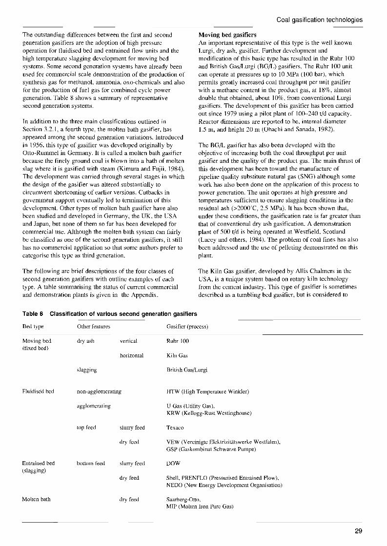
Table 8 Classification of various second generation gasifiers
Moving bed gasifiers An important representative of this type is the well known Lurgi, dry ash, gasifier. Further development and modification of this basic type has resulted in the Ruhr 100 and British Gas/Lurgi (BG/L) gasifiers. The Ruhr 100 unit can operate at pressures up to 10 MPa (l00 bar), which permits greatly increased coal throughput per unit gasifier with a methane content in the product gas, at 18%, almost double that obtained, about 10%, from conventional Lurgi gasifiers. The development of this gasifier has been carried out since 1979 using a pilot plant of 100-240 tid capacity. Reactor dimensions are reported to be, internal diameter 1.5 m, and height 20 m (Ohachi and Sanada, 1982).
The BG/L gasifier has also been developed with the objective of increasing both the coal throughput per unit gasifier and the quality of the product gas. The main thrust of this development has been toward the manufacture of pipeline quality substitute natural gas (SNG) although some work has also been done on the application of this process to power generation. The unit operates at high pressure and temperatures sufficient to ensure slagging conditions in the residual ash (>2000'C, 2.5 MPa). It has been shown that, under these conditions, the gasification rate is far greater than that of conventional dry ash gasification. A demonstration plant of 500 tid is being operated at Westfield, Scotland (Lacey and others, 1984). The problem of coal fines has also been addressed and the use of pelleting demonstrated on this plant.
The Kiln Gas gasifier, developed by Allis Chalmers in the USA, is a unique system based on rotary kiln technology from the cement industry. This type of gasifier is sometimes described as a tumbling bed gasifier, but is considered to
Bed type Other features Gasifier (process)
Moving bed (fixed bed)
Fluidised bed
Entrained bed (slagging)
Molten bath
dry ash vertical
horizontal
slagging
non-agglomerating
agglomerating
top feed slurry feed
dry feed
bottom feed slurry feed
dry feed
dry feed
Ruhr 100
Kiln Gas
British Gas/Lurgi
HTW (High Temperature Winkler)
U-Gas (Utility Gas), KRW (Kellogg-Rust Westinghouse)
Texaco
YEW (Vereinigte Elektrizitatswerke Westfalen), GSP (Gaskombinat Schwarze Pumpe)
DOW
Shell, PRENFLO (Pressurised Entrained Flow). NEDO (New Energy Development Organisation)
Saarberg-Otto, MIP (Molten Iron Pure Gas)
29

Coal gasification technologies
operate under conditions sufficiently similar for it to be classified among the moving bed types in this report. Because of the difficulty in providing an effective seal between the fixed ends and rotating chamber, pressure operation is one of the problems of this type of system. However, a demonstration plant of 600 tid has operated under 414 kPa since 1983 (Garside, 1986), at the Illinois Power Wood River Generating Station in the USA.
In conventional moving bed gasifiers, optimum coal size was between 5 and 50 mm. Sizes of coal outside this range, particularly fines, andlor strongly caking coals made them difficult to operate. The development of both the BG/Lurgi and Kiln Gas has produced units which can accept fine coal particles, less than 5 mm, and process strongly caking coals without difficulty.
Fluidised bed gasifiers As a general rule, fluidised bed gasifiers are operated at temperatures which do not cause ash fusion. However, enhanced performance which may be necessary for IGCC has been obtained from fluidised bed gasifiers, using high temperature and high pressure, in two ways.
Rheinbraun has chosen dry ash gasification and developed the High Temperature Winkler (HTW) gasifier. This gasifier can operate at 11 OOT and 1 MPa and a demonstration plant of 720 tid has been operating at Berrenrath, Germany since 1986 (Femmer and others, 1987).
Alternatively, ash agglomerating systems have been developed by the Institute of Gas Technology (IGT) and Kellogg-Rust-Westinghouse (KRW), both in the USA. These processes are the Utility-Gas (U-Gas) and KRW processes respectively. In these systems, the gasifiers are operated at temperatures of around 850-1 lOOT, at which some softening of ash particles does take place. Under these conditions small ash particles soften sufficiently to stick together to form larger and denser agglomerates, which eventually become large enough to defluidise and sink down through the bed to a suitable extractor.
The optimum coal size for fluidisation is considered to be between 0.5 and 3 mm. Pilot plants of 27 tid and 14-27 tid have been operated since 1974 and 1975 at Chicago (U-Gas) and Waltz Mill, PA (KRW), USA respectively (Schora and others, 1985; Haldipur and others, 1985).
Entrained flow gasifiers Gasifiers of the entrained flow type are the only ones from the second generation so far to have been put into commercial use. These are the coal-water slurry fed units developed by Texaco and commercialised by Tennessee Eastman and Southern California Edison in the USA, Ube Ammonia in Japan and Ruhrchemi in Germany. Two other units are under construction in China, a 400 tid gasifier for ammonia syngas at Lunan Fertilizer Company and an 1100 tid unit for fuel gas production at the Shougang Iron and Steel Works.
The entrained flow gasifiers listed in Table 8 are all operated under slagging conditions at temperatures of 1200°C or
higher, with coal ground to less than 0.1 mm particle size. Consequently, this type of gasifier is much less sensitive to fuel type and can gasify any kind of coal as well as solid residues such as those from coal liquefaction plants.
Another slurry fed gasifier is under development by Dow Chemical and a large scale demonstration unit commenced operation at Plaquemine, Louisiana in 1987. It is interesting to note that, at present, this is the largest unit gasifier operating in the world. Operation to date has been with low rank coal primarily and it is reported that this unit operates satisfactorily and meets its performance targets (Cornett, 1987). Future testing will involve conversion of the unit to operate with bituminous coal.
Two quite similar gasifiers, using dry coal feeding systems, have been developed from the original Koppers-Totzek (K-T) gasifier by Shell and Krupp-Koppers (PRENFLO) respectively. The significant advance over K-T technology, in both cases, is their ability to operate at high pressure. The main differences between the two lie in their burner arrangement operating conditions and details of the gas cooling sequence.
A third dry feed gasifier has also been developed by VEB Gaskombinat Schwarze Pumpe (GSP) in Germany. This unit has a different configuration from the Shell and PRENFLO systems in that it uses down-firing from the top into a reaction chamber which has extensive water cooling built into the containment walls. It is reported that 2-3% of the total heat input to the gasifier is transferred to the steam system through the wall cooling system (Rehwinkel and others, 1989). A 720 tid demonstration unit has logged more than four years operation.
The gasifier developed by Vereingte ElektriziUitswerke Westfalen (VEW) has a slightly different concept of gasification. In this case, coal is only partly gasified and, by design, unreacted char is removed from the gasifier and burned in a separate boiler to raise high pressure steam. Although the gasifier is a downshot entrained flow unit similar to Texaco, it is air-blown, uses dry coal feed and has cooling circuits embedded in the reactor walls. It is intended for use in a hybrid cycle, which does not need to achieve very high carbon conversion, and is rather beyond the scope of this report.
A gasifier developed by NEDO in Japan is under construction and expected to start its demonstration programme in 1991. It was designed to be an air-blown, two-stage entrained flow gasifier and make use of a dry coal feed system.
Molten bath gasifiers In this type of gasifier, finely ground coal and oxygen are blown on to the surface of, or directly into, a bath of molten material such as iron or fused salts of sodium carbonate. The gasification reactions take place in the bath where ash from the coal also melts and is retained. Gasification temperatures, usually above 1600T, are generally higher than those for the entrained flow systems. Consequently, molten bath units can accept any kind of coal provided only that it is first ground
30

Coal gasification technologies
to less then 3 mm in size. High pressure operation is available in these systems, with examples such as the gasifiers developed by Saarberg-Otto, the Molten Iron Pure-gas consortium (MIP) and ATGAS.
3.3 Process characteristics for efficient gasification
As discussed in Section 2.2, there are five major elements which contribute to the overall efficiency of any IGCC system. The greatest contributions come from the gas turbine and steam turbine cycles, which are beyond the scope of this report. In this section, the desirable characteristics of gasification systems for efficient IGCC applications are discussed and some attention given to problems for which development solutions are still required.
The conventional parameter to characterise any gasification system is cold gas efficiency, which is defined in terms of the higher heating value of product fuel at standard temperature and pressure and takes no account of any sensible heat either in the product gas or in any surplus steam recovered from the fuel conversion process, which also would be available for power generation. While high cold gas efficiency is a desirable goal and provides conditions for minimum integration of the several systems which make up the power plant, it is not essential for power generating systems.
The advantage of high cold gas efficiency for power generation systems lies in reduced need for close integration of the plant sections, in order to realise maximum cycle efficiency, and hence simpler overall plant design. However, as discussed in Section 2.2, more important is the overall fuel conversion efficiency, which includes sensible heat of the product gas and surplus steam. If a plant achieves a low cold gas efficiency, because the product gas is delivered hot and/or is accompanied by production of substantial amounts of surplus steam, close integration with the power generating systems in order to minimise losses of sensible heat, will still result in satisfactory overall plant efficiency.
The reactor itself is clearly the most important part of any gasification plant and has a strong influence on its performance. In order to improve efficiency of gasification, pressure operation has already been introduced in all types of second generation gasifiers. Other important factors are as follows:
high temperature; scale-up capability; load-following capability; coal feed systems; oxidants; gas cleanup systems.
3.3.1 High temperature
In a similar way to high pressure, high temperature augments gasification reaction rate which increases coal conversion and permits a higher coal throughput in any given gasifier.
The optimum temperature necessary for gasification is said to be about l300T which is derived from reaction rate of coal char and the composition of product gas. Too high a gasification temperature should be avoided because it requires unnecessarily high oxidant consumption and excess heat is removed from the gasifier in the form of sensible heat in the product gas. Such sensible heat must be recovered during downstream processing and put to good use in order to maintain the highest possible overall thermal efficiency in an IGCC system.
In the case of slagging gasifiers and depending on the ash fusion temperature of the coal feedstock, it may be necessary to operate at temperatures of 1500-2000°C or higher in order to melt the ash and maintain a fluid slag. This effect can be offset by the use of a fluxing agent, such as limestone, which reduces the melting temperature of the ash and improves the fluidity of the resulting slag.
In general, gasification temperatures for each type of gasifier fall into broad ranges, as follows:
750-900T for moving bed (dry ash); 850-1100°C for fluidised bed; 1200-2000°C for entrained flow.
A particular problem with high temperature gasification can sometimes occur in the form of accelerated deterioration of refractory linings on the reactor wall. Under high temperature operation, certain constituents of the molten slag may attack and penetrate into the lining. Compounds formed by these reactions may have low melting points, well below that of either the slag or the lining material, and these very fluid materials can then dissolve further refractory, leading to total destruction of the lining in quite short time periods under adverse conditions.
Careful selection of lining materials can minimise this attack with particular coals but it is not possible entirely to avoid the penetration of the lining under ash fusion conditions (Hirato, 1986). Consequently, in some types of slagging gasifier, a water cooling system is incorporated into the reactor wall which keeps down the temperature of the lining and limits the fluidity of any molten ash on its surface. In many cases this allows formation of a thin layer of solidified ash on the surface of the lining which protects it and inhibits further penetration by molten slag. Cooled walls may also have the advantage of greatly reduced quantities of refractory which reach a stable temperature gradient more quickly during start-ups.
The design life for the refractory lining in the Texaco gasifier at Cool Water, which does not incorporate water cooling, was only one year. In practice a life of four years was achieved when operating with the design coal, SUFCO (Cornett, 1987). This clearly demonstrated that, with proper attention to design and operation, extended refractory life could be achieved without resorting to wall cooling.
Selective evaluation of refractories to find an optimum material for application to slagging coal gasifiers was performed by Kennedy and his colleagues (Kennedy, 1981).
31

Coal gasification technologies
high iron oxide (20% FeO acidic coal slag (B/A = 0.55)
500 h at 1575°C with water cooling
Depth of corrosion, mm 0 10 15 20 25 40
Number/type Porosity, % Composition, wt%
2-FC A 120 3(99)
190-8 17 A 1203(92),Cr203(7.5),P205(0.5)
16-8 16 A 120 3(90) ,Cr203(10)
86-C 21 A 120 3(85),Cr20 3(1 0)P20 5(4.5)
109-C 23 A 1203(67),Cr203(32),P205(1)
D 260-8 25 A 12 0 3(67),Cr20 3(32)
228 mm400-8 13 MgO(42),Cr20 3(27),Fe20 3(16) length
38-FC 5 A 120 3(60),Cr20 3(27),MgO(6) m 114 mm ~ length
280-FC 7 A 120 3(65), Cr203(32)
22-FC 6 Cr203(80), MgO (8), Fe20 3(6)
relative corrosion resistances of water-cooled refractories exposed to a high iron oxide acidic coal slag forlfl500 h at 1575°C. The depth of corrosion was measured from the original position of the hot face.
FC = fused-cast
8 = sintered
C = chemically bonded
Figure 10 Corrosion resistance of water cooled refractories (Kennedy, 1981)
Results obtained from their corrosion and penetration tests are given in Figures 10 and 11. In these tests, the hot face of subject refractories were exposed to a synthetic, high iron, acidic coal slag (20% FeO with a base:acid ratio of 0.5), at a temperature of 1575'C for a period of 500 hours. The cold face in each case was water cooled such that the greater the length of test piece the hotter was the hot face.
The importance of high chromia content and high density in minimising the risk of slag attack is evident from these data. Even so, many of the materials tested, including some with 80% chromia content, exhibited some degree of cracking which, in most cases, could be attributed to thermal stress.
NEDO in Japan, provisionally selected 80% chromia and picrochromite rich materials for the refractory lining and thermowells to be employed in the 50 tid entrained flow slagging gasifier. which is now under construction in Kimitsu, Chiba-prefecture. However, results obtained from exposure tests performed in a 3 tid bench-scale gasifier at a temperature of about l650'C showed that while the 80% chromia refractory withstood the process atmosphere fairly well, picrochromite specimens and a thermowell made of this material were extensively damaged. The damage observed included cracks, slag penetration, dissolution or slag attack and breakdown of the bonding structure in the refractory (Japan's Sunshine Project, 1989).
for gasifiers operating at temperatures above 1600'C, the cooled wall design, comprising a thin refractory lining mounted on water cooled tubes, is the only practical solution. Slag then freezes on the wall until it reaches a thickness at which the heat transfer coefficient of the wall has fallen enough to allow molten slag to flow along the hot face. Effectively the interface between the reaction chamber and the wall is then composed of slag material and changes in composition as the ash content of the fuel changes; for gasifiers operating at lower temperatures, in the range 1400-1600'C, a thick refractory lining utilising chrome based materials holds promise of satisfactory performance (Firestone and others, 1981).
Number/type
2-FC
190-S
16-S
86-C
109-C
260-S
400-S
38-FC
280-FC
22-FC
Depth of penetration, mm
---5----10--~15----20---25
I 228 mm length
114 mm length
As far as currently available materials are concerned, it has been recommended that: Figure 11 Slag penetration of refractories (Kennedy, 1981)
32
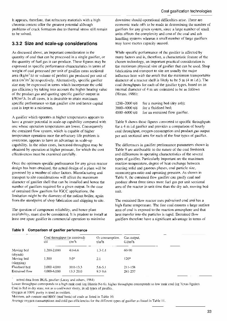
Coal gasification technologies
It appears, therefore, that refractory materials with a high chromia content offer the greatest potential although problems of crack formation due to thermal stress still remain to be solved.
3.3.2 Size and scale-up considerations
As discussed above, an important consideration is the quantity of coal that can be processed in a single gasifier, or the quantity of fuel gas it can produce. These figures may be expressed as specific performance characteristics in terms of weight of coal processed per unit of gasifier cross sectional area (kg/m2.h) or volume of product gas produced per unit of area (m3/m 2.h) respectively. Alternatively, specific gasifier size may be expressed in terms which incorporate the cold gas efficiency by taking into account the higher heating value of the product gas and quoting specific gasifier output in kW/m2.h. In all cases, it is desirable to attain maximum specific performance so that gasifier size and hence capital cost is kept to a minimum.
A gasifier which operates at higher temperatures appears to have a greater potential in scale-up capability compared with one whose operation temperatures are lower. Consequently the entrained flow system, which is capable of higher temperature operation once the refractory life problem is overcome, appears to have an advantage in scale-up capability. In the other cases, increased throughput may be obtained by operation at higher pressure, for which the cost effectiveness must be examined carefully.
Once the optimum specific performance for any given reactor design has been obtained, the actual design of a plant will be governed by a number of other factors. Manufacturing and transport to site considerations will affect the maximum diameter of gasifier shell that can be installed and hence the number of gasifiers required for a given output. In the case of entrained flow gasifiers for IGCC applications, the limitation might be the diameter of the radiant boiler, again from the standpoint of shop fabrication and shipping to site.
The question of component reliability, and hence plant availability, must also be considered. It is prudent to install at least one spare gasifier in commercial operation to minimise
Table 9 Comparison of gasifier performance
downtime should operational difficulties arise. There are economic trade-offs to be made in determining the number of gasifiers for any given system, since a large number of small units affects the complexity and cost of the coal and ash handling systems whereas a small number of large gasifiers may leave excess capacity unused.
While specific performance of the gasifier is affected by many factors and is, therefore, a characteristic feature of the chosen technology, an important practical consideration is the maximum physical size of gasifier that can be used. Shop fabrication and transport to site are usually the major influence here with the result that the maximum transportable diameter of a reactor shell is likely to be 5 m (4 m i.d.). The coal throughputs for each of the gasifier types, based on an internal diameter of 4 m are estimated to be as follows (Hirato, 1986):
1200-2000 tid for a moving bed (dry ash); 3000-4000 tid for a fluidised bed; 4000-6000 tid for an entrained flow gasifier.
Table 9 shows these figures converted to specific throughputs for a 4 m i.d gasifier and provides a comparison of hourly coal throughput, oxygen consumption and product gas output per unit sectional area for each of the four types of gasifier.
The differences in gasifier performance parameters shown in Table 9 are attributable to the nature of the coal feedstock and differences in operating characteristics of the several types of gasifier. Particularly important are the maximum reaction temperature, degree of heat exchange between reacting solid and gaseous phases, coal particle size, steam:oxygen ratio and operating pressure. As shown in Table 9, the entrained flow gasifier can gasify coal and produce about three times more fuel gas per unit sectional area of the reactor in unit time than the dry ash, moving bed unit.
The entrained flow reactor uses pulverised coal and has a high flame temperature. The fine coal ensures a large surface area of coal is exposed to the reaction atmosphere and that heat transfer into the particles is rapid. Entrained flow gasifiers therefore have a significant advantage in terms of
Coal throughput (as received) tid t/m2h
02 consumption, t/m2h
Gas output, GJ/m2h
Moving bed (dryash) Moving bed (slagging) Fluidised bed Entrained flow
l,200-2,000
1,500
3,000-4,000 4,000-6,000
4.0-6.6
5.0*
10.0-13.3 l3.3-20.0
l.3-1.4
2.l
5.6-5.1 9.3-9.6
60-90
120*
211-158 281-257
* actual data from BG/L gasifier (Lacey and others, 1984) Lower throughput corresponds to a high rank coal (eg I1linois No 6), higher throughput corresponds to low rank coal (eg Texas lignite), Coal is fed in dry state, not as a coal/water slurry, in all types of gasifier. Oxygen at 100% purity is used as oxidant. Moisture, ash content and HHV (maf basis) of coals as listed in Table 10. Average oxygen consumptions and cold gas efficiencies for the different types of gasifier as listed in Table II.
33

Coal gasification technologies
Table 10 Coal properties (Dawkins and others, 1985)
Moisture, Ash, HHV, wt% wt% GJ/t (maf)
High rank coal 12.0 8.8 33.0 Low rank coal 34.9 10.8 29.2
Table 11 Oxygen consumption and cold gas efficiency
02 consumption!, Cold gas efficiency, % kg(kg coal (maf) High rank coal Low rank coal
Moving bed (dry ash) 0.432 846 866
(slagging) 0.533 887
Fluidised bed 0.71 4 80.84 74.84
Entrained flow 0.885 81 8 81 8
I Oxygen purity assumed to be 100% 2 Rio Turbio coal in a Lurgi gasifier (Hebden and Stroud, 1981) 3 Markham coal in a BG(L gasifier (Lacey and others, 1984) 4 Average of Illinois No 6 and Texas lignite gasification in a KRW
unit (Dawkins and others, 1985) 5 Average of illinois No 6 and Texas lignite gasification in a Shell
unit (Hartman and others, 1983) Westfield coal and North Dakota lignite gasification (Hebden, 1981)
7 (Thompson and others, 1987) 8 illinois No 6 and Texas lignite gasification in a Shell unit
(Van der Burgt and Van Klinken, 1986)
the throughput per unit gasifier. There is a penalty in terms of oxygen consumption. As shown in Table 11 the entrained flow gasifier requires about twice as much oxygen per kilogram of coal processed than the moving bed (dry ash) system.
Both moving bed types have the advantage of counter current flow between the incoming coal and exit product gas. This provides good heat exchange and ensures sensible heat in the product gas is retained in the gasifier. In the slagging version of the moving bed system, this feature assumes even greater importance because of the high temperatures required in the slag melting zone. Consequently, oxygen consumption per unit area in the slagging version of the moving bed gasifier is only slightly larger than that of the dry ash version and there is noticeable improvement in specific coal throughput and product gas output.
The moving bed system was primarily developed for the production of synthesis or pipeline gas, where high cold gas efficiency is a much more important consideration than is the case for IGCC applications. This could be a useful advantage for future developments where coal gasification is added to an existing oil or natural gas fired combined cycle system. In such cases, the minimum integration allowed by high cold gas efficiency should simplify the extent of modification required to the existing systems.
The main disadvantage of the moving bed system is the requirement for sized coal, which also leads to longer reaction times because of the smaller exposed surface area and requirement to penetrate the larger particles. Some of the
limitation on fines content has been overcome in recent development work although, as discussed in Section 3.1.5, coals with a high proportion of fines may call for special treatment. It is also necessary to incorporate systems for the recovery of tar and oils in order to recycle them back to the gasifier.
The fluidised bed system has many of the advantages of the entrained flow. Although it does require a slightly larger particle size the effect of this is partly offset by the advantages of excellent mixing and high heat exchange characteristic of fluidised beds. As a result, coal throughput and product gas output approach those of the entrained flow system. Good distribution of heat throughout the coal mass means less heat production from direct oxidation of coal is required and hence a lower maximum temperature. Oxygen consumption, therefore, is also less than that required by the entrained flow.
The main disadvantage in this case is a rather high unburned carbon loss, at about 5%, which also results from intimate mixing of unreacted coal with spent ash and, although related to coal characteristics to some degree, so far seems unavoidable. It may prove possible, with further development, to recover this carbon and use it in a carbon bum-up cell.
3.3.3 Load following capability
Part load operation and ability to follow changes of load, without significant loss of gasification efficiency, are important characteristics for systems which must meet the operating requirements of electric utilities. The quantities of oxidant and coal injected into the gasifier must be adjusted during flexible load operation. Manipulation of the oxidant stream, which is gaseous, is relatively straightforward, although some buffer storage capacity may be required, to account for load changes in the air separation system, whereas adjusting the coal feed rate, especially across a substantial pressure boundary, can present some difficulty.
Flexible load operation is comparatively easy in moving bed and fluidised bed gasifiers, because heat capacity is large and each of these types of gasifier retains an inventory of unreacted fuel. Quick response load changes can be made by adjusting the flow of oxidant and allowing slight variations in the fuel inventory to offset any delays necessarily incurred in the coal handling system.
For example, it has been reported that the throughput of the BG/L moving bed gasifier could be varied rapidly with no control problems. The gasifier could also be put on standby quite easily and returned rapidly to gasification, thus allowing for intermittent on-load operation of the gasifier when necessary to meet product gas requirements (Thompson and Vierrath, 1988).
Similarly for fluidised bed gasifiers, it has been reported for the HTW gasifier that the oxygen:fuel ratio could be maintained within quite close limits during changes in load, because the screw feed system, used for coal injection, provides sensitive control over the fuel in close relationship
34

Coal gasification technologies
to corresponding adjustments in the supply of oxygen. Consequently, this gasifier exhibited excellent part load operating performance (Engelhard and others, 1987). Although it was found difficult to perform load following tests on the demonstration unit, because the plant's control system had not been designed to meet these requirements, this gasifier did attain load variation rates of 4% to 8%/min in the 60% to 100% load range, as shown in Figure 12 (Engelhard and Adlhoch, 1988).
In entrained flow gasifiers, flexible load operation is possibly more precise than in the other two types because close control of the fuel:oxidant ratio is more critical. This is because these gasifiers have a smaller heat capacity, and almost no inventory of process feedstock. In order to maintain a stable flame close to the injector tip, the coal and oxidant flow ratio must be maintained within narrow limits throughout the entire operating range, so that all the flows have to be adjusted simultaneously.
The flame is sustained in a fuel rich environment and, while it is important to ensure the temperature is maintained at a level adequate to produce a fluid slag, the conditions must not be allowed to approach stoichiometric, which would produce excessive temperatures inside the gasifier, possibly above the operating limit of any refractory linings. The response of this system is likely to be governed by the flexibility of the coal feed system and this is the reason some developers have favoured a coal slurry feed, with the objective of obtaining fuel flow adjustment capability similar to that obtainable with oil.
Testing of load changing and load following has been conducted on entrained flow gasifiers. At Cool Water, load changes of 20% at a ramp rate of greater than 4% per minute have been achieved. Dynamic load testing has been conducted both with the gasification plant leading and with the combined cycle system leading. The test results are shown in Figure 13 and are within the range of load following requirements normally required by a utility 10-50% load changes at 1-3% per minute (Watts and others, 1987). Partial load operation tests were also conducted successfully down to 45% of the design plant net power output. Carbon conversion decreased only slightly although combined cycle efficiency deteriorated significantly at very low loads as shown in Table 12 (Watts and others, 1987).
Other examples of flexible load operation in entrained flow gasifiers are shown in Figures 14 and 15 for the PRENFLO gasifier. Figure 14 shows a quick response to load change from 100% to 50% and back to 100%. Figure 15 shows rate of change of load changing, which meets the requirements of a gas turbine engine (Modem Power Systems, 1989).
It is evident, therefore, that adequate flexible load operation has been demonstrated by all three major types of gasifier, although the entrained system might be considered to have some advantage because its control requirements are more critical, and it has performed well in this respect at Cool Water. Consequently, flexible operation capability need not be a major point of evaluation in choosing a type of gasifier
100
.0 0'
::; 90 0~
d' -0 80 c CIl
Cii 0 () 70 "0 (lJ (f) CIl e:> () 60 c
50 0
130
:s: ::?:
110?£ 0
:;:::
>OJ
CD 90 c (lJ
(f) CIl OJ
;:: 70 CIl a:
I
50 I 0
Figure 12 Load variation at the HTW demonstration plant
plant load set point 120
96
72
48
24
I 10%/minuteI ... ~
I
4 6 8 102 I minutes 1
I I I
II I I I I
I I I
11 11 II II II II I
1 II I
II II 8%/minute
~I' .. II I I I I I I, , ,
.~ 8 10 I minutes I I I I I
start
2 6 I
I end I
Load variatiOn from 60%· :0 100%
gas turbine power
steam turbine power
OL------,-------r-------r------,-------, 20.53 20.59 21.05 21.11 21.17 21.23
Time, h/min on 22 January 1986
20% load increase at 4.5% per min The gas turbine completed transition in 4.5 minutes, but the slower steam cycle does not reach steady state until 12 minutes later.
Figure 13 Illinois No 6 load following test
35
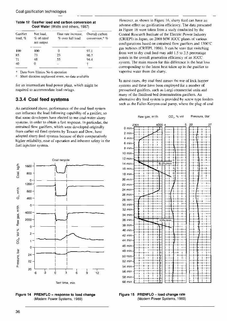
Coal gasification technologies
Table 12 Gasifier load and carbon conversion at Cool Water (Watts and others, 1987)
Gasifier Net load, Heat rate increase, Overall carbon load, % % of rated % over full load conversion,* %
net output
100 100 0 97.1 85 73 23 96.7 71 48 55 94.4 40 0 t
* Data from Illinios No 6 operation t Short duration unplanned event, no data available
for an intermediate load power plant, which might be required to accommodate load swings.
3.3.4 Coal feed systems
As mentioned above, performance of the coal feed system can influence the load following capability of a gasifier, so that some developers have elected to use coal-water slurry systems, in order to obtain a fast response. In particular, the entrained flow gasifiers, which were developed originally from earlier oil fired systems by Texaco and Dow, have adopted slurry feed systems because of their comparatively higher reliability, ease of operation and inherent safety in the fuel injection system.
1600
(ij o 800 ()
Coal recycle
...JU ...'--------I 1 I I
0-+-------+---1--------- 1200
800
N u-o 400
I 0-+------1----+-------
I I 4000
~------2000
2
N o ()
24
22
20
I
0-+-----+----+-------
-6 -3 o 3 6 9 12
Test time, min
However, as shown in Figure 16, slurry feed can have an adverse effect on gasification efficiency. The data presented in Figure 16 were taken from a study conducted by the Central Research Institute of the Electric Power Industry (CRIEPI) in Japan, on 2000 MW IGCC plants of various configurations based on entrained flow gasifiers and 1300'C gas turbines (CRIEPI, 1986). It can be seen that switching from wet to dry coal feed may add 1.5 to 2.5 percentage points in the overall generation efficiency of an IGCC system. The main reason for this difference is the heat loss corresponding to the latent heat taken up in the gasifier to vaporise water from the slurry.
In most cases, dry coal feed means the use of lock hopper systems and these have been employed for a number of pressurised gasifiers, such as Lurgi commercial units and many of the fluidised bed demonstration gasifiers. An alternative dry feed system is provided by screw type feeders such as the Fuller-Kenyon coal pump, where the plug of coal
Raw gas, m3/h CO2 , % vol Pressure, Bar
o min
2 min
4 min
6 min
8 min
10 min
12 min
14 min
16 min
18 min
20 min
22 min
24 min
26 min
28 min
30 min
32 min
34 min
36 min
38 min
40 min
42 min
44 min
46 min
48 min
50 min
52 min
54 min
56 min
58 min
60 min
5
--t--t- --t--f-
--t--t---t--t- --t--t- ---\--t- --t--t-
---\- --t- --t- --t- ---\- --t- --t- --t- --t- ---\- --t- --t- --t- --t- --t- ---\---t---t- --t ---\
==+ __ = - ==t:13%/m!n: --+--t--t- --t- --+---\---\--+--t --t--t--t--+--+ --t--t--t--t--t --t---\---\--t--t --t---\--t--t--t --t--t--t--t--t --t---\--t--t--t --+ --t--t --t--t --+--t--t--t--t --+--t--+--t--t --+---\--t--t--t --t--t--t--t--t --t--t--t--t--t --t--t--t--t--t --t--t--t--t--t --t--t--t--t--t --+--t--t--+--t --t--t--t--t--t --t--t--t--t--+ --t--t--t--t--t --t--t--t--t--t --t--t--t--t --t
22 27
--t--.J---+--+---+--I---t--t- -+:f+--t -- t ---+-l+--t--t- --t- --+--t- --t--- --t--t- --+-- --+--t- --t-- --t--t- --t-- --+--t- --+--- --+--t- --+-- --t--t- --t-- -+--t- --+-- -t--t- --t--- -t--t- --t--t -t--t- --t--t -t--t- --t--t -t--t-- --t-- -t--t- --r-- -t--t- --t-- -t---t- --t--- --t--t- --t-- --t--t- --t- --t---+----t- --t--t- --t- t--t--t- --t- t--t--t- --t- t--t--t- --t- t--t--t-- --t- --t--t- --t-- --t--t- --t-- --t---t---t-- --t---t- --t-- --t--+----t-- --t--t- --t-- -t---t- --t-- -t--t- --t-- -t--+----t-- -t--t- --t-- -t--t- ---\-- -t--t- --t--t -t--t-
==r=--t----t- --t- --t- --t- --t- --t---t- --t- ---\---t- --t- --t- --t- --t- --t- --t-
-=t==t==--+---t---t--t- --t--t- --t--t- --t--t- --t--t- --t--t- --t--t- --t--t- --t --t---t--t- --t--t- --t--t- --t--t- --t--+----t--t- --t--+--
Figure 14 PRENFLO - response to load change Figure 15 PRENFLO - load change rate (Modern Power Systems, 1989) (Modern Power Systems, 1989)
36

Coal gasification technologies
Table 13 Comparison of 'dry' and 'wet' feed systems: gasification data (Vogt and others, 1983)
Feed to gasifier Coal dried to Coal as received Water added to coal gasifier data 2% moisture 16.5% moisture 20% 40% 80%
Coal (AR), kg* to process 1000 1000 1000 1000 1000 to auxiliaries 45 15 0 0 0
Moisture removed, kg 145 Water added, kg 220 400 815 Oxygen to gasifier, kg 680 770 815 860 1040 Steam to gasifier, kg 15 02/maft coal ratio 0.92 0.99 1.07 1.16 1.35 HP:j: steam produced, kg 1180 1315 1500 1720 2180 Raw gas produced, m3 1590 1750 1990 2250 2730 H2+CO produced. m3 1510 1430 1350 1245 1060 Raw gas composition. vol % H2O 1.7 9.0 18.6 27.3 41.4 H2 28.7 27.8 26.0 23.3 18.1 CO 65.6 54.0 41.7 32.5 20.5 CO2 1.6 7.0 11.8 15.1 18.5 H2S 1.5 1.4 1.2 1.1 0.9 N2+Ar 0.9 0.8 0.7 0.7 0.6
* Illinois No 6: as received (AR), 16.5 % moisture, 7.6% ash t Moisture and ash-free coal :j: High-pressure steam
Dhot gas cleanup
> 43 . cold gas cleanup I ~ 42 ~ 0
>. '-' 41c Q)
·u ~ 40 Q)
co (;j 39 > 0
38
_~ slurry feed ---- --~
Figure 16 IGCC efficiency dependency on gasification efficiency (CRIEPI, 1986)
held in the screw flights holds back the pressure in the gasifier. Screw feed systems have been applied with some success to fluidised bed gasifiers (Engelhard and others, 1987).
Dry coal feeding has been applied to entrained flow gasifiers by other developers such as VEW, Shell, PRENFLO and NEDO. For example, the demonstration unit operated by Shell at the Deer Park facility in Texas is the latest and the largest plant demonstrating the applicability of the dry feed system.
Another study on the comparison between dry and slurry feed systems was made by SIPM (Shell International Petroleum Maatschappij). As shown in Tables 13 and 14 the production of synthesis gas (H2+CO) and net plant efficiency decrease with increasing amounts of water added to coal.
As shown in Tables 13 and 14. oxygen consumption, output of non-combustible gases, such as C02 and H20, in the product gas and in-plant energy requirements all increase with increasing water added to the feed. At the same time, the content of combustible gases, such as H2 and CO, decreases quite markedly with consequent adverse effect on net gasification efficiency. These effects are shown plotted in Figure 17.
In slurry fed gasifiers, not only is valuable heat generated by combustion used to evaporate water in slurry, but also valuable carbon and oxygen are used to generate non-combustible C02 and steam which carry sensible heat away from the gasifier. In addition to lower thermal efficiency of gasifiers, C02 can affect the performance of downstream desulphurisation, because C02 itself is an acid gas like H2S and may be taken up preferentially by some of the sorbents used in the scrubbers.
From these results, it is evident that the dry coal feed offers advantages in terms of increased efficiency of the gasifier and overall IGCC power generation system. There is, therefore, substantial incentive to persevere with development of these systems to improve flexibility and reliability.
3.3.5 Oxidant
The choice of either oxygen or air as the oxidant for gasification also has an important influence on overall efficiency of an IGCC system. In particular, it has a major effect on the consumption of power within the plant because of the need for large compressors in the air separation plant. This was discussed in Section 2.2 under consideration of the overall generation efficiency and it has been the subject of
37

Coal gasification technologies
Table 14 Comparison of 'dry' and 'wet' feed systems: net plant efficiency (Vogt and others, 1983)
Feed to gasifier Coal dried to Coal as received. Water added to coal gasifier data 2% moisture 16.5% moisture 20% 40% 80%
Coal (AR) to process* 100 100 100 100 100 Raw product gas 81.2 77.3 72.5 67.1 56.6 HP steam producedt 16.0 18.3 20.9 24.1 30.2
Plant energy requirement: steam to gasifier 0.2 electric power:j: 18.5 19.6 20.9 22.5 25.7 heat for drying 1.9
Total 20.6 19.6 20.9 22.5 25.7
Total coal in 104.6 101.3 100 100 100 Total raw gas out 81.2 77.3 72.5 67.1 56.6 Total HP steam out 0 0 0 1.6 4.5 Net efficiency 77.6 76.3 72.5 68.7 61.1
* Heat content of coal, as received (AR), to process is set at 100 and other values in table are calculated relative to it. Heat content is based on net heat of combustion. Raw gas is at its dew-point temperature and latent heat not included.
t Heat content of steam is based on heat content of equivalent amount of coal required to raise steam. High pressure (HP) steam is at 1450 psi (10,000 kPa) and 520°C.
:j: Heat content of power is based on heat content of equivalent amount of coal required to raise power.
production. Other examples are given in Table 15, which Table 15 Selected gasifier characteristics (Makansi, 1987) shows that the proportion of auxiliary power for three types
Gasifier vendor Carbon Oxidant Auxiliary of gasifiers, mainly required for oxygen production, varies conversion required, power, from 10 to 14% of gross power generation. efficiency, % kg/GJ fuel % of power
Similar results were obtained from a comparative study Texaco 99+ 38.6 14.1 (Schwartz, 1982) on the cost and efficiency of both air-blown BGClLurgi 99+ 22.1 9.7 and oxygen-blown IGCC plants conducted by Westinghouse, KRW 94.9 29.8 11.0
partly under contract to the USDOE (DE-ACOI-79ET 14672). Selected results from this study are given in
several case studies. Results obtained by CRIEPI in Japan Tables 16 and 17. Table 16 lists leading performance (CRIEPI, 1986) are included in Figure 16, which shows that parameters for each system and shows that, while the plants for several options, air-blown IGCC systems have a higher were of comparable size, the efficiency of the air-blown overall efficiency than equivalent cases using oxygen. system was about 2% above that of the oxygen-blown case.
This correlates well with the information presented in Experience in the Cool Water demonstration project showed Figure 16, where the maximum difference in overall cycle that the oxygen plant consumed about 17 MWe of the efficiency between air- and oxygen-blown cases is about 2% 117 MWe, total electricity generated by the IGCC plant even though the gasification system on which the two studies (Curran,1987). This means that, in this case, almost 15% of are based are not the same. Costs are given in Table 17, the gross output was consumed internally for oxygen where a 7% advantage in favour of the air-blown system can
100
90
80
Q) C)
70
C'"Q)
~ 60 Q)
0..
50
40
30
be seen.
Table 16 Plant performance summary for coal throughput of 240 t/h (Schwartz, 1982)
Net efficiency
Case A Case B ,,~~ Parameter air blown oxygen blown
(H2+CO~, Coal feed rate, t/h 240 240
'~ Coal energy in (HHV) MW 1,721 1,721 Combustion turbine output, kW 420,199 444,373(H 2 + CO) = combustible content of product gas
Reheat steam turbine output, kW 280,540 264,453 20 40 60 Total gross power output, kW 700,739 708,826 Total moisture, % Auxiliary power consumption, kW 44,340 84,805
Net power, kW 656,399 624,021 Figure 17 Effect of moisture in coal on gasification Heat rate, kJ/kWh 9,438 9,929
efficiency Overall thennal efficiency, % 38.1 36.3
38

Coal gasification technologies
The largest cost difference noted in Table 17 appears in the plant area labelled oxidant compression, which includes the air separation plant in the oxygen-blown case. Differences in this section of the plant result in a ten-fold cost differential between the two systems. This difference is offset, to some extent, by higher costs in the gasification section of the air-blown plant where the equipment units are necessarily larger in order to handle the greater volume of gas which must be processed in this case. Gas volumes in air-blown systems are greater because of the added nitrogen, which enters the gasifier in the air used to provide the oxidant and plays little or no part in the process beyond acting as a diluent in the gas stream and a carrier of sensible heat.
The higher cost of the combined cycle section of the plant for the oxygen-blown case, by about 10%, is due to the added complexity necessary to accommodate steam injection into the gas turbine combustor, which is required for NOx
control. No steam injection is required for the air-blown case because the large quantity of N2 in the low Btu gas acts as a diluent and helps to prevent the combustion temperature from reaching high enough levels to promote fixation of nitrogen as NO x• It is worth noting that gas turbine manufactures are introducing low NOx combustors which do not now need steam injection. Nitrogen from the air separation plant is also
Table 17 Comparison of system capital cost estimates for coal throughput of 240 t/h (Schwartz, 1982)
1981 installed cost, M$ Plant area Case A Case B
air blown oxygen blown
Coal receiving and conveying Coal preparation Oxidant compression, and air
separation plant for case B Coal pressurisation,
gasification, particulate recovery, ash handling, raw gas recovery, gas quench, and recylce gas compression
Sulphur recovery and tail gas treating
Acid gas removal Process condensate treating and
ammonia recovery Primary water treatment Waste water treatment Cooling water system Effluent water treatment Combined cycle power generation Flare, instrument air, fire
protection, etc Process plant sub total
Off sites, office bldg, maintenance shop, lab, warehouse, reagent and by-product storeage personnel facilities
Engineering, home office costs, fee and project management
Contingencies (25% of process plant cost)
Total plant investment
9.0 14.0 8.8
136.0
21.2
19.9 26.1
8.7 4.4
14.4 2.5
130.0 4.6
399.6
40.4
44.1
99.9
584.0
9.0 14.0 80.0
90.0
18.2
16.5 23.4
6.6 4.0
17.2 2.2
143.0 4.6
428.7
43.6
47.5
107.2
627.0
available for temperature control so that the differential should be less with more modem systems.
There is, therefore, considerable incentive toward the use of air as the oxidant for IGCC systems. As yet, the selection of oxidant is seldom independent of the choice of gasifier and not all gasifiers can operate in the air-blown mode. The low heat content of fuel gas obtained from air-blown gasifiers may also limit the choice of gas turbine available with capacity to bum such fuels reliably. Nevertheless, development towards the use of air as the preferred oxidant for gasifiers in IGCC systems is attractive because it offers systems that are more efficient, less expensive to build and simpler in design than comparable oxygen-blown systems.
However, the oxygen-blown system does have advantages, such as higher carbon conversion, smaller component sizes in the gas-making train and higher product gas heating value. Overall plant efficiency would be improved if the auxiliary power requirement could be reduced in order to minimise the performance penalty which this represents. A possible approach appears to be the use of compressed air extracted from the gas turbine as feedstock for the air separation unit, since this would allow closer integration of the air separation system into the overall process, with consequent beneficial effect on the energy balance.
There are indications that the industrial gas companies, who normally provide the air separation equipment, are aware of the existing limitations resulting from the use of separate, stand alone, air separation systems and some effort is being applied to explore the possibility of more integrated systems. Such a development could help to offset the apparent advantage of air-blown systems and allow the real advantages of oxygen-blown systems, such as higher carbon conversion and smaller equipment sizes, to compete as important factors in future process selection.
3.3.6 Gas cleanup
One of the principal reasons for adopting the gasification route to generate electric power is the possibility it offers for control of atmospheric emissions. A wide variety of
.existing commercial and well developed gas processing systems is available, which can be applied for removal of sulphur, ammonia and other undesirables from the product gas.
Product gas cleanup not only provides for superior control over emissions to the environment but also affords protection to the gas turbine. Direct use of coal derived fuels in gas turbines has given rise to deposition, erosion and corrosion (DEC) problems in the past but these should not arise if the gases can be cleaned sufficiently before being delivered to the engine.
Typical limits of various impurities in fuel gas that may be imposed by gas turbine manufacturers are quoted in Table 18. Raw coal gas may contain 500-1000 ppm of sulphur compounds, mainly in the form of H2S, and up to 10 g/m3 of particulates comprising ash and unreacted char, which also contains several of the impurities listed in
39

Coal gasification technologies
Table 18 Typical limits of impurities in the fuel gas for gas turbines (Kuwabara, 1986)
Impurities Dimension Concentration limit
Particulates (maximum size <40 11m) mg/m3 20-30 Alkali metals (Na, K, etc) ppm 0.05-0.08 Halogens (Cl, F, etc) ppm 0.4-0.6 Vanadium ppm 0.03-0.05
Table 18. The gas processing associated with coal gasification systems usually includes removal of particulates and H2S.
Many kinds of gas cleanup systems have been employed in coal gasification systems over the years. For the most part, these have been low temperature systems involving the use of various liquids with either an organic or aqueous base. Particulates can easily be removed by water scrubbing. The temperature of the scrubber is generally at around the boiling point of water, about 150"C, at the pressures employed. Consequently the gas stream must be cooled before admission to the scrubbing towers. This implies the use of waste heat boilers and the introduction of unavoidable heat by-pass as discussed in Section 2.2
For primary removal of H2S from the gas stream a variety of systems have been developed and applied quite widely. Many of these were developed for the town gas industry, when gas manufactured from coal was distributed before the widespread use of natural gas. Typical H2S removal systems popularly employed in the demonstration plants, are as follows:
Rectisol (cryogenic methanol) BG/Lurgi, HTW; Selexol (polyethylene glycol + ether) Texaco, PRENFLO; Hot potassium carbonate (K2C03 + water) BG/Lurgi.
Rectisol and Selexol are methods based on physical solvent techniques which are more effective under lower temperatures and higher pressures. Usually Rectisol operates at --60 to -70T, which necessitates cooling of the gas stream, most probably by the introduction of heat by-pass to the system. The solvent can be regenerated to release H2S for subsequent processing to elemental sulphur. The Selexol process operates at about 40"C and, again, regeneration of the solvent produces H2S.
Both methods can be operated with strong selectivity toward H2S absorption, although Rectisol can also be used to remove C02 and NH3. There is little or no chemical reaction between the solvent and the acid gases in either case. It is also worth noting that, in both cases, the solvents are organic and contain nothing that might be harmful to gas turbine components should minor carry-over occur.
Hot potassium carbonate in aqueous solution, in processes such as Benfield, operates at higher temperatures of about 100-140"C and does involve chemical reaction with the acid gases being stripped. Here again, regeneration of the solvent produces a by-product stream of sour gas containing H2S for
subsequent further processing to yield elemental sulphur or sulphuric acid as saleable by-products.
In some cases, the concentration of H2S in the acid gas stream may be so low that the familiar Claus process cannot be applied economically for the production of saleable sulphur. Alternatives such as the catalytic Selectox process have been developed for application in such circumstances. It is also worth noting that modern designs for secondary processing usually arrange for any tail gases to be recycled back to the gasifier in the interests of zero emissions.
A drawback associated with the hot carbonate system is that potassium is among the elements that can attack blade materials in gas turbines, as listed in Table 18. Depending upon the form in which potassium reaches the blades, trace amounts can lead to severe attack so that solvent carry-over must be prevented.
Another system, the Stretford process, uses a more sophisticated aqueous solvent to trap H2S but has the advantage that regeneration, by blowing air through the solvent, produces elemental sulphur directly without further processing. Chemical reactions are involved and build up of undesirable by-products in the recirculating solvent stream must be controlled by continuous bleed which requires disposal (Taylor, 1988). A possible disadvantage of this process is the use of sodium vanadate among the reactants.
Both sodium and vanadium are among the elements cited in Table 18 as being aggressive toward gas turbine components, even when present in trace amounts. There must be no possibility of any solvent carry-over, therefore, to ensure that traces of either sodium or vanadium do not reach the turbine blades and promote corrosive attack.
Relatively speaking, all the liquid solvent processes could be classed as cold gas cleaning because some cooling of the gasifier outlet gas prior to processing is usually required. Such cooling necessarily introduces heat by-pass into the overall system with consequent adverse effect on cycle efficiency, as discussed in Section 2.2. Systems involving the use of chemically active solvents have the added disadvantage that many of the chemicals concerned are detrimental to the life of gas turbine blades, even in trace amounts.
To overcome these disadvantages, much attention has been given to the development of hot dry gas cleaning techniques that could be applied directly at the gasifier outlet. Comparison between cold and hot gas cleaning techniques were also part of the CRIEPI study whose results are summarised in Figure 16. This shows that the advantage in cycle efficiency to be gained from using hot gas cleaning can be as much as 2.5%. This result can be substantiated from Figure Sa, which shows that a 10% reduction in heat by-pass, as in the case when hot gas cleaning replaces the cold gas system, does yield about 2% increase in overall cycle efficiency.
Research and development programmes on various hot and dry gas cleanup systems are now well advanced, especially in
40

the USA under the sponsorship of EPRI and in the DOE's Gas Stream Cleanup (GSCU) Programme. These include high temperature filter systems for particulate removal and the use of solid regenerable sorbents such as zinc ferrite for the control of HzS. Details of this work are reviewed in Chapter 4.
3.4 Comparison of processes Tables 19 and 20 present summaries of typical gasification conditions and performance of selected second generation gasifiers. A general comparison of the main classes of gasifier in this category has been given in Section 3.3, in relation to important process considerations including scale-up capability and load following. This section provides further detailed assessment of the capabilities of particular proprietary gasification systems within three of the four main classes, on the basis of published information. The molten
Coal gasification technologies
bath system is excluded here because it is considered to be less well advanced than the other systems and unlikely to be applied to IGCC demonstration plants in the foreseeable future.
Selection of the eight systems chosen for more detailed consideration here was made in accordance with their ability to meet the following criteria:
maturity of technology; potential for application to IGCC demonstration plants in the near future, including high pressure operation, tolerance to a wide range of coals and high coal throughput or good scale-up prospects; availability of published data, as far as possible on a common basis, from which to make the evaluation.
Of these criteria, the greatest difficulty was experienced in
Table 19 Types and typical gasification conditions of selected gasifiers
Gasifier Bed Ash Feed Oxidant Steam Pressure, Temperature, DC type type fuel size, mm MPa reaction exit
BG/L moving slagging dry B,SB 5-50 O2 + 2.5 >2000 450 HTW fluidised dry dry Lig <6 02/air + 1.0 <1000 850-900 V-Gas fluidised agglomerating dry B,SB <6 02/air + 0.4-3.2 950-1090 NA KRW fluidised agglomerating dry B,SB <5 02/air + 2.1 870-1040 <1010 Texaco entrained slagging slurry B <0.5 02 4.1 1260-1540 <800 DOW entrained slagging slurry SB,Lig NA O2 2.2 1320-1430 <1,038 Shell entrained slagging dry B,Lig <0.1 02 + 3.0 2000 900 PRENFLO entrained slagging dry B,SB,Lig <0.1 O2 + 3.0 1500-2000 1350-1600* GSP entrained slagging dry SB,Lig <0.2 O2 + 3.0 1600-2000 NA
* temperature of exit gas before quenching by cold gas B bituminous coal SB subbituminous coal Lig lignite NA data not availab!e
Table 20 Typical performance of the selected gasifiers
Steam Carbon Product gas Cold gas O2 consumption*1 consumption conversion, HHV, efficiency,
Gasifier kg/kg-coal, maf kg/kg-coal, maf % MJ/m3 % Remarks
BG/L 0.52 HTW 0.54 V-gas nla KRW*6 0.68 Texaco 0.9 Dow*9 0.86*10
GSP 0.8 Shell* 12 0.89 PRENFLO*16 1.03
0.36 0.36 nla 0.44 0*7 0*10
0.3 0.3*14
0.06
99.9 96 95.3*4
95 97.2*7 98.9*10
98 99*13
99.3
13.2 11.5 5.0*5
12.1 10.1 *7 9.8*11
10.8 11.2*13
11.8
88 85 69.6*5
80.8 74.3*8 77*11
85 81.0*15
79.6
bituminous coal, liquor production*2 brown coal*3
bituminous coal bituminous coal bituminous coal subbituminous coal subbituminous coal bituminous coal subbituminous coal
*1 Oxygen consumption depends on coal properties, ash fusion temperature and required performance considerations
*2 Thompson, 1987, 1988 *3 Engelhard, 1988 *4 oxygen, actual, Schora and others, 1985 *5 air, design basis: Patel and Schora, 1986 *6 design basis; Dawkins and others, 1985 *7 Clark, 1988 *8 Cool Water, 1986
*9 design basis * 10 Fisackerly, 1987 *11 Henley, 1986 *12 design basis *13 Hartman, 1983 *14 Lacey, 1988 *15 Van der Burgt, 1986 *16 Wetzel, 1988 nla not available
41

Coal gasification technologies
obtaining data on a common basis. As identified in Table 20, it has been found necessary to use design data, actual performance results from both pilot and demonstration plants and even projections for proposed commercial systems, in order to cover the whole range. It is recognised that projections for commercial systems tend to be optimistic and this possibility has been taken into consideration in these assessments.
3.4.1 Moving bed gasifier
The BG/Lurgi gasifier has successfully combined features of both moving bed and high temperature gasifiers. It can operate with temperatures in the combustion zone higher than 2000T. Consequently, coal throughput and carbon conversion are far greater than conventional dry ash moving bed gasifiers. It has also been reported as having excellent load flexibility which can be attributed to its high heat capacity.
An important feature of this gasifier is the counter-current flow between incoming coal and emerging gases. The high temperature heat produced by char combustion in the oxidation zone at the bottom of the reactor bed is effectively utilised in the upper zones of the coal bed, in sequence from thebottom, for gasification, carbonisation and finally drying of the incoming coal. This can be recognised from the large differences between the reaction temperature (>2000T) and exit gas temperature (450T) shown in Table 19. The BG/Lurgi's low oxygen consumption and high thermal efficiency are attributable to this heat recovery feature of the gasifier.
The BG/Lurgi gasifier operates with graded coal. This represents another advantage over other systems in the auxiliary power which might otherwise be necessary to grind coal feed stocks. Fines can be injected separately into the combustion zone although it may be preferable to process the fines, for example by agglomeration to enable them to be gasified, unless separately fired steam raising facilities are available to make direct use of them. In this gasifier, ash is withdrawn from the reaction zone as a molten slag which is immediately quenched with water and eventually rejected from the gasifier vessel as glassy frit. This material is reported to be inert and suitable for disposal with no hazard to the environment (Lacey and others, 1984).
The counter-current flow arrangement of this gasifier ensures that volatiles are distilled from the coal at quite a low temperature so that little, if any, cracking occurs. The exit gas therefore contains significant amounts of volatile hydrocarbons together with condensable tar, oil and phenolic aqueous liquors. One advantage of this is that, with proper downstream processing, the final product gas retains methane and higher light hydrocarbons, even after the gas cleanup stage, resulting in a high heating value and high cold gas efficiency, as shown in Table 20.
However, the presence of condensable tar, oils and other compounds in the raw gas does present special problems for the downstream processing stages, where these materials must be recovered and either recycled to the gasifier or
otherwise processed for disposal. For this reason, the application of a hot and dry gas cleaning system may be difficult in this case because of the potential for blocked filters and deposition on surfaces of solid sorbents resulting in their rapid deactivation.
Although development of the slagging system has obviated the need for the rotating grate and mechanical ash removal systems that tended to limit scale-up capability in the dry ash Lurgi gasifier, this system still requires mechanical moving parts in the cool zone at the top of the bed to distribute the coal feed and agitate the upper section of the bed to prevent agglomeration with caking coals. Gasifiers up to 5 m diameter have been built. The main size limitation is one of transport to site in order to make maximum use of shop fabrication.
A particular advantage of the BG/Lurgi technology for IGCC applications may come from its high cold gas efficiency. This results in much lower heat by-pass than that produced by other systems so that efficient cycles can be developed with a minimum of integration in this case. As noted in Section 3.3.2 this could be helpful when a coal gasification system is to be added to an existing oil or natural gas fired combined cycle system.
3.4.2 Fluidised bed gasifiers
Except in the particular cases of the 'U' gas and KRW gasifiers, fluidised bed gasifiers operate at temperatures which do not normally exceed the ash fusion temperature of the coal. Therefore, as seen in Table 19, the reaction temperatures are the lowest among the several gasifier types. Consequently, oxygen consumption is lower than that for slagging gasifiers. However, carbon conversion is also lower. When compared with entrained flow gasifiers, fluidised beds have advantages in terms of auxiliary power consumption both for air separation and feed coal preparation.
As shown in Figure 18, a disadvantage of low temperatures within the normal gasification range is higher C02 formation. This represents a loss of valuable carbon and oxygen to form a gas which has no value as a fuel for the gas turbine. The presence of C02 also can adversely affect removal of H2S in wet scrubber systems. For example, ammonium carbonate may deposit and cause obstruction in pipelines when the temperature is low. However, when satisfactory hot and dry gas cleanup systems become available, these problems are expected to become less important.
As mentioned in Section 3.3, fluidised bed gasifiers generally have advantages in load flexibility over entrained flow systems. There is no production of condensable tars, oils or phenolic liquors and this represents an advantage over moving bed gasifiers.
High temperature Winkler (HTW) The HTW demonstration plant has so far been operated to produce synthesis gas for methanol production, so that little information about product gas heating value and cold gas efficiency has been made available. Typical figures quoted by Rheinbraun are given in Tables 19 and 20. Gasification
42

Coal gasification technologies
pressure at 1.0 MPa is the lowest among the eight gasifiers considered here and demonstration of higher pressure operation, at up to 2.5 MPa will be required for worthwhile integration in IGCC schemes.
The HTW unit is the only gasifier among the eight which operates under completely dry ash conditions. The ash withdrawn from the reactor, which also tends to contain a significant proportion of unconverted carbon, is fed to a boiler system where this carbon is burned to provide heat for steam raising. This additional step is characteristic of fluidised bed gasifiers and not needed with other systems. Although the possibility of leaching of undesirable constituents from reject ash disposed to landfill requires further investigation, it is anticipated that this material will be found similar to the ash rejected from moving bed gasifiers. By extrapolation from the data given in Section 2.] .2, therefore, it is expected that HTW ash should conform to RCRA standards.
The applicability of this gasifier to an IGCC system should
moving fluidised entrained bedbed bed
'C ~ ---. 0.80 ,-----,----.----rl---,---+--.----.--+-.--+---.-----,
0.76
0.72
0.68
0.64
0.60
0.56 H20
0.52
~ 048 > C 044 o :e ~ 040 0
§ 0.36 u
~ 0.32 (9
0.28
0.24
0.20
0.16
0.12
0.08
0.04
450 600 750 900 1050 1200 1350 1500
Gasification temperature. K
Calculated data for equilibrium at 50 atmosphere pressure
when the hydrogen:oxygen ratio = 3
Figure 18 Gas composition versus gas temperature (Baron, 1975)
be evaluated when data from 2.5 MPa operation become available.
V-Gas The U-Gas gasifier uses the principle of agglomeration for collection of ash within the reaction chamber. In this system, low fusion temperature components of the ash are encouraged to melt and act as a binder, attracting other unfused ash constituents, to form agglomerates. The advantage of this is that, unlike the slagging gasifier, complete melting of all the ash is not necessary and the requirement for fluxing agents eliminated. It is reported that disposal of the agglomerated ash to landfill does not give rise to environmental problems (Patel and Schora, 1986).
The turndown capability of this gasifier is reported to be 3: 1 (Patel and Schora, 1986). This gasifier can also tolerate fluctuations in both the fluidised bed depth and carbon:ash ratio within the bed. However, the flexibility in operating temperature of agglomerating gasifiers is not great, especially toward the upper limit where careful control is necessary to avoid excessive melting. This is essential to avoid the formation of large agglomerates which might cause clogging of the sloping grid and, eventually, loss of fluidisation. Uniform fluidisation of the bed is also important to control formation of the agglomerates. Consequently, ease of operation with this type of gasifier seems to be less satisfactory than others among the four types of gasifier listed in Table 19.
The limited performance data published to date for this gasifier are not sufficient to permit thorough assessment of its performance capability. Oxygen and steam consumption figures are not available while published product gas HHV and cold gas efficiency relate only to the air-blown version. More comprehensive operating data need to be made available for this system in order to assess its true capability for IGCC applications.
Kellogg Rust Westinghouse (KRW) The KRW unit is also an agglomerating fluidised bed gasifier, and the operating conditions are almost the same as those of the U-Gas system. The major difference is in the ash extraction system at the base of the gasifier. In the KRW case, coal is fed from the bottom of the reactor through a nozzle which also injects air or oxygen to be mixed with coal. Devolatilisation of coal and combustion take place in a zone close to the nozzle and the hot products quickly mix into the bed.
Steam is introduced separately into the bed to gasify char. Ash agglomeration occurs only on the edge of the combustion zone, so that as before, operation of this region is critical to satisfactory performance of the gasifier. Agglomerated ash is cooled in the bulk of the fluidised bed where endothermic gasification takes place. The fluidised bed is well mixed and agitated by the central stream of hot products emerging from the nozzle and by side streams of steam and transport gas that are injected through secondary nozzles.
Unlike the U-Gas unit, the KRW gasifier does not use a
43

Coal gasification technologies
fixed distributor plate to support the bed or act as the oxidant distributor. This overcomes the difficulties associated with a fixed diaphragm located in the hottest region of the gasifier and appears to be an advantage of the KRW for scale-up capability.
3.4.3 Entrained flow gasifiers
As shown in Table 19, all five entrained flow gasifiers are slagging systems. To keep the ash in a molten state with a viscosity low enough to ensure that it flows down the reactor wall into the water filled quenching chamber, the operating temperature of this type of gasifier must be kept above the ash fusion temperature.
High temperature gasification has an advantage in achieving high carbon conversion and high coal throughput which leads to high scale-up capability. However, oxygen consumption, necessary to maintain the high gasification temperature, is greater than for the other two types of gasifier. When compared with the BG/Lurgi system, which also operates under slagging conditions, oxygen consumption is higher and thermal efficiency in the entrained flow case is substantially lower, as shown in Table 20.
In entrained flow reactors, product gases are cooled to below the ash solidification temperature, either by quenching with cool recycle gas or by radiant heat transfer to membrane water-walls. This minimises any risk of ash precipitation on tube walls downstream of the reactors. The temperature of the product gases at the reactor exit is in the order of 1l00--1300°C for slurry fed reactors and 1400--1600T for dry fed reactors. At the reactor exit, the gases are cooled down to 800-1000°C depending on ash fusion temperature.
No condensable tars, oils or phenolic liquors are formed in this type of gasifier. Reject ash withdrawn from the reactor is in the form of glass frit and is not expected to give rise to any leaching problem when deposited in a landfill.
Because of the low concentration of coal char retained in the reaction chamber of an entrained flow gasifier at any instant, the heat storage capacity is low and this affects both load flexibility and turndown capability. Maintenance of the gasification temperature above ash fusion point is a critical operating condition for this type of gasifier and requires simultaneous variation of both coal and oxidant streams, in quite close relationship to one another. The main disadvantages of this system, therefore, are the critical control characteristics and high auxiliary power consumption for air separation, especially for slurry fed gasifiers, and additional power required for fine coal grinding duties.
Texaco Texaco is one of two slurry fed, entrained flow type gasifiers currently undergoing demonstration. As mentioned in Section 3.3.4, slurry feed is a disadvantage from a thermal efficiency standpoint, when compared with the possibility of dry feed and leads to a higher content of C02 (17-20%) in the product gas. This reduces the heating value of the product gas and can adversely affect the efficiency of wet desulphurisation systems as mentioned in Section 3.4.2.
The main advantage of this system is the high degree of technical readiness. Texaco gasifiers have been used for the production of synthesis gas in a number of commercial installations. The slurry feed system simplifies the control characteristics and obviates the requirement for a supply (')f reaction steam for control of reaction zone temperatures.
Commercial scale gasifiers have been installed by both Tennessee Eastman and UBE Chemicals for the production of synthesis gas, although in these installation the product is cooled by direct quenching rather than radiant boilers. This process also has the advantage of having been chosen for the demonstration plant at Cool Water when product gas cooling did use a radiant boiler. A quenched gasifier is also available, as an alternate at this facility. It has, therefore, been demonstrated under utility operating conditions for a number of years with conspicuous success.
DOW The DOW system features another slurry feed type gasifier which has some characteristics similar to the Texaco unit, described above. The main difference between the two is that the DOW system uses two-stage coal injection near the base of the gasifier. In the first stage, combustion of coal takes place to produce much of the heat necessary for gasification which takes place primarily in the second stage. Part of the coal slurry is fed directly to the second stage where carbonisation and gasification take place mainly under the action of heat produced in the first stage. This two-stage system appears to have an advantage in thermal efficiency, when compared with the single stage system, as shown in Table 20. This is because the system makes more efficient use of the high grade heat in the gasification stage with less being rejected to the downstream coolers.
Beside those mentioned above, the DOW gasifier has other advantageous features. One is that an uncooled hot wall design has been adopted for the first stage reactor and this offers potential for considerable improvement in the thermal efficiency with this gasifier. The design life of the refractory lining on the hot wall was set conservatively at one to two years and the materials selected on the basis of extensive pilot plant testing. It is reported that material selection, in conjunction with the advanced temperature control applied to this gasifier, has provided a satisfactory life for the hot face refractory (Webb and Moser, 1988).
Also employed in the DOW gasifier is an ash withdrawal system which does not use the traditional lock hopper approach. The DOW ash withdrawal system is made up of two crushers in series which crush the glassy frit of ash into fine particles and withdraw them continuously. Unfortunately only limited operating data have been made available upon which to evaluate the performance of this promising system.
One of the disadvantages of the DOW gasifier is in its char recycle system. Char separated from raw gas in a cyclone is water quenched, let down in pressure, thickened and added to the raw coal slurry. The char slurry recycled to the reactor constitutes up to 10-15% of total slurry feed. The cooled char recycle system results in noticeable losses of both thermal
44

Coal gasification technologies
and pressure energy so that a hot char recycle is under consideration for the Plaquemine demonstration unit.
Shell The Shell entrained flow gasifier, which is a pressurised development from the atmospheric pressure Koppers-Totzek unit of the 1950s, has the advantage of a dry coal feed system. with consequent benefit in terms of thermal efficiency. Low C02 content of the product gas is also due to the dry feed and high gasification temperature. Low steam consumption as shown in Table 20 suggests that residual moisture in the coal has been effectively used in reactions taking place in this gasifier.
Although some details of the performance experienced in the Shell demonstration unit at Deer Park in Texas have been made available in the public domain to date, this developer prefers to enter a suitable agreement with interested utilities before allowing access to detailed data upon which to make assessments of the potential of this system. It has been selected by Samenwerkende Electriciteits Productiebedrijven NY (SEP) in the Netherlands for a new 250 MWe demonstration plant to be built at Buggenum.
PRENFLO The PRENFLO system, which is also a development from Koppers-Totzek technology, is quite similar to Shell.
Table 21 Evaluation of selected gasifiers
Performance characteristics for this system are also shown in Tables 19 and 20. This gasifier has an arrangement of four burners, at right angles to each other in a horizontal plane. This is expected to provide a more stable flame than other horizontally opposed, burner systems. C02 content of the product gas in this case is also about 2% and steam consumption is also low, or zero, as shown in Table 20.
3.5 Evaluation of selected gasifiers The technical evaluation of the selected gasifiers, as discussed in detail in the foregoing sections, is summarised in Table 21, where rankings A, B and C are allocated under eight headings and defined as follows:
A Having the greatest potential or the lowest in-plant power consumption.
B Having considerable potential or medium in-plant power consumption.
C Having not so much potential or the highest in-plant power consumption.
For true comparison, the oxygen-blown version of each gasifier was considered in each case.
Plant Versatility Scale-up Load Auxilliary Air-blown Experience of Applicability Gasifier performance of fuel capability flexibility power operability demo-plant to IGee
BG/L A e B A A e A A Dow B B A e e e A A GSP B e A B B B e B HTW e*l B B B A A e*2 e*3
KRW B B B B A A e B PRENFLO B A A B B B B A Shell B A A B B B B A Texaco A A A A e B A A V-gas e*l B B B B A e e*l
* I ranked below due to lack of data *2 HTW has a long experience of 720 tid plant operation, but not high pressure p~2.0 MPa operation *3 ranked below due to no high pressure operation experience
45

4 Status of hot dry gas cleaning technologies
An important aspect of technology improvement for efficient IGCC systems is the development of hot and dry gas cleanup systems. This chapter describes the status of the development of these systems and discusses the approaches which appear to have the greatest potential at present.
As seen in Table 19, the temperature of raw gases at the exit of gasifiers is commonly in the range of 800-1000'C. Maintaining those temperature levels as high as possible during subsequent cleaning of the gases contributes considerably to increased efficiency of gasification systems and also IGCC systems. The development of hot and dry gas cleanup systems which can operate at temperatures of similar range to those of the raw gases has been promoted to meet such a requirement.
In this section, various kinds of high temperature and high pressure dust removal systems and sulphur removal systems are reviewed, together with dry and hot systems for ammonia and alkali metal removal.
4.1 Dust removal systems There are many kinds of dry and hot dust removal systems under development aimed at application to PFBC and gasification/turbine combined cycle systems. A major part of this work is being performed under US DOE's Gas Stream Cleanup (GSCU) Programme. These systems can roughly be classified as follows:
High temperature electrostatic precipitators Moving granular collectors Rigid ceramic filters
porous ceramic filters porous sintered ceramic filters
Ceramic fabric filters Ceramic fibre filters Metallic felt filters
Temperatures, pressures, surface areas and periods of operation achieved in various pilot-scale systems are summarised in Figure 19.
Many investigators of these systems report outlet dust concentrations in the range of 1-20 ppm which can meet not only the environmental emission standards in USA and European countries (Table 22) but also the estimated tolerances for gas turbines as shown in Table 18.
4.1.1 Electrostatic precipitators
The application of electrostatic precipitation techniques to high temperature and pressure PFBC and gasification gases has been studied by Curtiss-Wright, USA, CRIEPI in Japan, University of Essen, Germany and others. A summary of the test results from pilot and bench-scale plants in the USA is shown in Table 23. As an example, a tube-type electrostatic precipitator (ESP) of Curtiss-Wright is depicted in Figure 20.
The Curtiss-Wright ESP was manufactured by Cottrell Environmental Science (CES) under the sponsorship of the
Table 22 Particulate emission limits (Tassicker, 1986)
Country Ib/106 Btu ng/J g/ma3 ppm
USA 0.03 12.9 0.036* 28* West Gemany 0.042* 18.1 * 0.050 39 European 0.042* 18.1 * 0.050 39 Community Australia 0.21* 90.3* 0.250 194 Sweden 0.047 20.2 0.056* 43*
* These conversions cannot be made exactly. The conversions cited are based upon: heating value of coal 26 MJ/kg (11,200 Btu/lb) 1 kg coal - 12 kg combustion gas ma3 = 1 cubic metre gas at O°C and 1 bar ppm - parts per million by mass
46

----
----
Status of hot dry gas cleaning technologies
-pressure bar area m2
---1&9 1.4 granular --1 0.63 ceramic hybrid
10 27 ceramic candles I 6 39 ESP I
1 0.63 ceramic hybrid I700
800
900
~ 600~ ceramic candles iii Cii
5.7:J 15
Q.
E ~ 500
1 8.5 ceramic fabric I
granular15-20
1-3.6 1.0
1-3.6 430
I400'
ceramic candles
300 metallic felt I
200 I I I 10 100 1,000 10,000
Operational hours,
Figure 19 Pilot-scale filters treating gasifier or PFBC gas (Tassicker and Drenker, 1987)
US DOE. This device had nine cylindrical electrodes in 95-99.5%, before an accidental flood of cold water damaged parallel providing 39 m2 of collecting area. The unit operated the electrodes (Tassicker, 1986). satisfactorily for 100 hours at temperatures of 650-790T at a pressure of 570 kPa, and attained collection efficiencies of A single tube-type ESP under test at the CRIEPI Yokosuka
Table 23 Test results for ESPs at elevated temperatures (Tassicker, 1986)
CES Bureau of CES CES CES Denver CES Union Mines Combustion EPA Curtiss- Research NYU Carbide CES Power Wright Institute
Dates tested 1962-64 1963-68 1966-68 1976-77 1982-83 1982-85 1986-87 Test location Institute Morgantown Montebello Bound Brook Woodridge Denver NY NY
WV WV CA NJ NJ CO Combustion PFBC coal natural gas methanol air fuels gas PFBC coal methanol PFBC coal Dust type fly ash fly ash alumina & ash no dust fly ash CW fly ash fly ash Temperature, °C 500-700 800 900 540-1090 790-850 790-900 880 Pressure, bar 3-8.1 4.5-6.5 4.6-11.2 1-35.5 5.4-6.4 6.4-10 10 Gas flow, m3/S 0.1 0.16 0.11 0.53-5.59 0.054-0.097 0.57 Gas Velocity m/s 0.2-1.2 0.3-1.1 2.9 0.83-0.93 0.76-1.37 0.68 No. Collector tubes 19 16 1 1 9 1 Ducts Length of tubes, m 1.83 1.83 4.6 0.76 4.6 2.1 Par plates Dia of tubes, m 0.15 0.15 0.20 0.073 0.30 0.30 0.3 spacing Collection area, m2 16.4 13.8 2.9 0.17 39 2 21 Discharge electrodes wire wire twisted wire mast vanes cy1 vanes rods & barbs Dia Disch Elect, mm 2.1,3.4 2.1 3x2.8 1.58,2.34,3.18 25.4,76 167083 50 SCA, m2/m3/s 166 45 26.6 66.1-73.6 36 37 Dust load, ppm 550-1700 2300-3700 1500-2000 3000 Dust dia, micron 2.6 30 6-10 5 5 Efficiency, % 98.8 91-96 80-82 95-99.5 95-99.5
47

Status o'f hot dry gas cleaning technologies
70 KV
inlet~
IT
ash
Figure 20 Tube-type precipitator (Tassicker, 1986)
Institute in Japan is one of the few examples of ESP tests applied for fuel gas from coal gasifiers. The collection efficiency is not available at the present time.
Dust from coal gasifiers generally contains a certain amount of coal char, which has a lower resistivity and enables this material to be collected more efficiently than particulates released from PFBC systems (Klingspor and Vernon, 1988).
4.1.2 Moving granular collectors
As illustrated in Figure 21, a moving granular collector captures particulates from coal gases passing through filter media which move slowly and continuously by gravity down the containment vessel. The dust laden filter media are then sent to a separation system where they are cleaned by a vibrating screen and recycled to the top of the collector vessel. Silica sands are generally used as the media.
The main features of the moving granular collector are as follows:
continuous self-cleaning property; easy disposal of the captured dust;
stable high efficiency, which is insensitive to changes in chemical and electrical properties of the dust; wide adjustability to changes of load.
The Coal Mining Research Centre (CMRC) and Kawasaki Heavy Industries of Japan have jointly developed a two stage granular collector; which is installed in connection with a 40 tid fluidised bed gasifier in Yubari Test Facility of NEDO, Japan.
An efficiency of 99.8% has been successfully obtained under the conditions of 1.8-1.9 MPa pressure, 430-460°C and inlet dust concentration of 1-5 g/m3. Cumulative test periods logged some 900 hours by February 1986 (Hozumi and others, 1986b). Another pilot-scale granular bed filter is being tested at the pressurised fluidised bed test facility at New York University under the sponsorship of the US Department of Energy. The filter is a hybrid system of granular bed and baghouse which was developed by Combustion Power Co.
.. gas in
Figure 21 Kawasaki granular bed filter
dust
bucket elevator
48
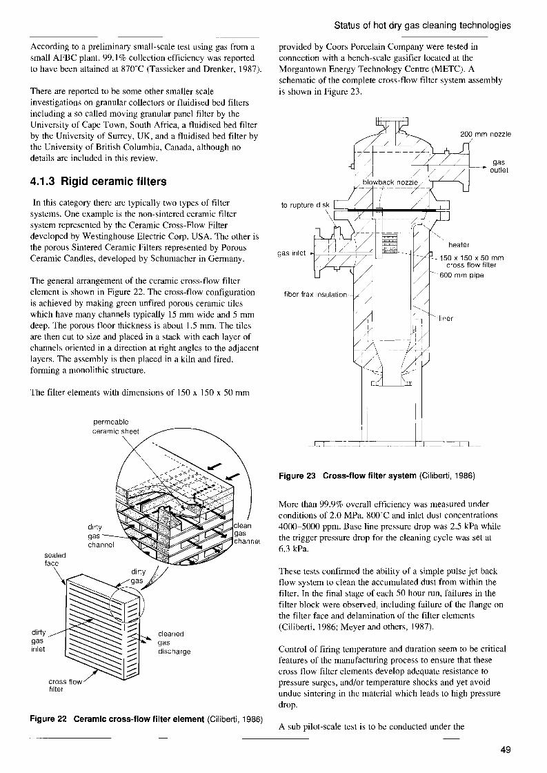
cleaned gas discharge
dirty gas channel
Status of hot dry gas cleaning technologies
According to a preliminary small-scale test using gas from a small AFBC plant, 99.1 % collection efficiency was reported to have been attained at 870°C (Tassicker and Drenker, 1987).
There are reported to be some other smaller scale investigations on granular collectors or fluidised bed filters including a so called moving granular panel filter by the University of Cape Town, South Africa, a fluidised bed filter by the University of Surrey, UK, and a fluidised bed filter by the University of British Columbia, Canada, although no details are included in this review.
4.1.3 Rigid ceramic filters
In this category there are typically two types of filter systems. One example is the non-sintered ceramic filter system represented by the Ceramic Cross-Flow Filter developed by Westinghouse Electric Corp. USA. The other is the porous Sintered Ceramic Filters represented by Porous Ceramic Candles, developed by Schumacher in Germany.
The general arrangement of the ceramic cross-flow filter element is shown in Figure 22. The cross-flow configuration is achieved by making green unfired porous ceramic tiles which have many channels typically 15 mm wide and 5 mm deep. The porous floor thickness is about 1.5 mm. The tiles are then cut to size and placed in a stack with each layer of channels oriented in a direction at right angles to the adjacent layers. The assembly is then placed in a kiln and fired, forming a monolithic structure.
The filter elements with dimensions of 150 x 150 x 50 mm
permeable ceramic sheet
dirty gas inlet
cross flow filter
provided by Coors Porcelain Company were tested in connection with a bench-scale gasifier located at the Morgantown Energy Technology Centre (METC). A schematic of the complete cross-flow filter system assembly is shown in Figure 23.
-liner
heater
150x150x50mm cross flow filter
- 600 mm pipe
gas~=+::::;:::,'::::::;=:=:::;::jf---- outlet
fiber frax insulation-
gas inlet4=~~-=~=;;:~
Figure 23 Cross-flow filter system (Ciliberti, 1986)
More than 99.9% overall efficiency was measured under conditions of 2.0 MPa, 800°C and inlet dust concentrations 4000-5000 ppm. Base line pressure drop was 2.5 kPa while the trigger pressure drop for the cleaning cycle was set at 6.3 kPa.
These tests confirmed the ability of a simple pulse jet back flow system to clean the accumulated dust from within the filter. In the final stage of each 50 hour run, failures in the filter block were observed, including failure of the flange on the filter face and delamination of the filter elements (Ciliberti, 1986; Meyer and others, 1987).
Control of firing temperature and duration seem to be critical features of the manufacturing process to ensure that these cross flow filter elements develop adequate resistance to pressure surges, and/or temperature shocks and yet avoid undue sintering in the material which leads to high pressure drop.
Figure 22 Ceramic cross-flow filter element (Ciliberti, 1986) A sub pilot-scale test is to be conducted under the
49

Status of hot dry gas cleaning technologies
sponsorship of the US DOE using an array of full-scale filter elements (300 x 300 x 100 mm) in the PFBC unit operated by the University of New York.
There are many other works on filter systems belonging to the category of Porous Sintered Ceramic Filters. For example, cylinders or candles, composed mainly of silicon carbide particles or fibres, have been undergoing tests in various programmes since 1984. The best known example of the candle filter, which has been employed in a number of test programmes, is that developed by Schumacher in Germany. The pressure drop of this kind of filter in the clean condition is low. Filtration occurs at the surface without particle penetration (Tassicker and Drenker, 1987).
manway
refractory lining' metal lining
fibre insulation
instrumentation manifold
pulse cleaning manifolds
tube sheet
tube sheet gusset gas & solids from -...._--J-H pre-cleaning shroud
filter elements impact plate
hot air in .. (preheat)
-f-Hl-----heating coils
~ to screw cooler and lockhoppers
Figure 24 Pilot-scale candle filter module at Grimethorpe (Reed, 1987)
The largest filter of this type containing 130 x 1.5 m long ceramic candles, provided by Schumacher, has been tested at the Grimethorpe PFBC Establishment, UK under the sponsorship of the Electric Power Research Institute (EPRI) of USA. A schematic of the complete filter module is shown in Figure 24.
From commissioning in March 1987, more than 600 hours of tests were logged by October 1987 under the conditions of inlet gas temperature of 776-862°C, pressure of 720 to 1050 kPa and a filtration velocity up to 0.04 mls achieving 99.4-99.7% efficiency.
Some difficulty was experienced with the tube sheet
Table 24 Summary of candle operating characteristics over 2000 cycles (Lippert and others, 1986)
Operating pressure drop characteristics Filter before Average velocity baseline, cleaning, difference, cycle time
Cycle m/minute mbar mbar mbar minutes
0-100 1.8 50.8 56.0 (5.2) 18 2.7 75.4 82.9 (7.5) 17 3.6 125.5 164.3 (38.8) 19 4.6 179.3 186.7 (7.4) 7
100-463 3.6 145.4 164.3 (18.9) 13 159.4 179.3 (19.9) 7 178.3 189.2 (10.9) 9
464-905 3.6 169.3 186.7 (17.4) 8 162.3 179.3 (17.0) 5 210.6 224.1 (13.4) 5
906-1482 2.7 148.4 161.8 (12.4) 7 141.4 149.4 (8) 9 142.4 149.4 (6) 8
1483-2005 2.7 155.4 169.3 (13.9) 7 169.3 174.3 (5) 4 180.3 194.2 (13.9) 6
mounting joint, which necessitated modification and supply of cooling air. Problems also arose with the candle to tube sheet seals when operating at off design conditions. However, it is expected that this experience will make it possible to design a full-scale filter module with much improved performance, reliability and tolerance to variations in operating conditions.
Tests on candle filters are also being carried out in many other institutions such as Rheinisch-Westfalische Technische Hochschule (RWTH), Aachen, Germany (six elements, 100-400T, atmospheric pressure, cumulative test periods 1,500 hours), KRW Energy Systems, Waltz Mill, USA (33 elements, and 550-590T, 1.5 MPa), Calver-APT, Inc, USA (12 elements, Tier Filter Structure, collection area 3 m2,
cumulative test periods 600 hours), and Westinghouse EC, Pittsburgh, USA (single candle, 870°C, 1.4 MPa).
As shown in Tables 24 and 25 published by Westinghouse, although the base line pressure drop of the candle filter is high, it appears comparatively stable with time after each cleaning cycle. This implies that dust particles do not penetrate into the micro pores of the filter. Cleaning of the filter is performed quite easily by a jet pulse and high collection efficiency of more than 99% is maintained, as shown in Table 25.
4.1.4 Ceramic fabric filters
Woven ceramic fabrics may also be applied to high temperature and pressure coal gas cleaning. A 1000 hour durability test of a filter of nine bag array has been carried out by Westinghouse at a stoker boiler of the University of North Dakota sponsored by EPRI. The ceramic bag filters were woven from Nextel fibres supplied by the 3M
50

Status of hot dry gas cleaning technologies
Table 25 Summary of candle performance (Lippert and others, 1986)
Test Filter Inlet dust Collection run velocity, concentration, efficiency,
Cycle m/minute ppm %
0-5 8054 99.99 <1 6-14 5362 99.91 5 15-18 4080 99.96 2
2 19-29 4.6 1956 99.87 3 30-82 4.6 1677 99.84 3
3 83-91 4.6 777 98.76 10 92-229 3.6 970 99.85 2 230-245 3.6 970 99.02 10
4 246-463 3.6 1377 99.87 2
5 464-474 3.6 1942 99.08 18 475-648 3.6 2158 99.09 20
6 649-741 3.6 2230 98.90 24 742-797 3.6 2230 97.47 57 798-905 3.6 2230 * *
7 941-986 2.7 3099 99.35 20 987-1118 2.7 3099 99.96 1
8 1119-14822.7 2183 99.25 16
9 1483-1892 2.7 2122 99.97 <1
10 1893-2005 2.7 3809 99.98 <I
* dust sampling line leak
Table 26 Summary of performance of recent HTHP bag filter tests (Lippert and others, 1986)
Test Test hours
Number of cleaning cycles
Filter face Collection velocity, efficiency, m/minute %
(feet/minute)
Single bag 10.8 cm x 1.5 m fibersi1 cloth (carborundum)
20 70 2.0 (6.5)
99.97
2 bag array 10.1 cm x 1.5 m 3M Co Nextel 5H 2/1 (30x30)
10 20 1.1 (3.0)
99.98
2 bag array 10.1 cm x 15 m 3M Co Nexte1 5H 3/0 (30x37.5)
50 50 1.8 (6.0)
99.96
Company. These fibres are composed of alumina, boria and silica in a 3: 1:2 mole ratio. A bag is 156 mm i.d. x 2.44 m length. The test was conducted at atmospheric pressure and 455'C. A collection efficiency of more than 99% was attained throughout the run of 882 hours. No damage to the
bag material was observed, although ash fusion on the fabric surface was noted together with formation of creases in the fabric (White and others, 1986).
4.1.5 Ceramic fibre filters
One of the filters belonging to this category is the Alumina-Silica Fibre Filter developed by the University of Essen, Germany. The filter element is made from short alumimo-silica fibres which are partially sintered together. Tests have been conducted under atmospheric pressure and at temperatures of 800 to 950'C. More than 99.9% efficiency has been achieved at face velocities of 1.8 to 3 m/min with maximum pressure drop of 2 to 4 kPa. The material of this filter element is light in weight, resilient and needs no internal support mandrel (Tassicker and Drenker, 1987).
Another filter involved in this category is the Ceramic Fibre-Ceramic Matrix Filter, developed by ORNL. This ceramic fibre-ceramic matrix composite is made by chemical vapour deposition. In this process, a reactive gas which decomposes to Silicon Carbide (SiC) at high temperature (l200'C) is forced through a fibrous Silicon Carbide (Nicalon) preform. A ceramic matrix material is thus deposited on the fibres, bonding them together, and partially filling the space between fibres. The volume and density of the fibre in the composite are up to 60% and 90%, respectively. Because of the fibre reinforcement, such a composite has shown exceptional strain tolerance, thus overcoming the problem of brittle fracture which limits the performance of many ceramic based materials.
The Nicalon felt with Nicalon cloth on one or both sides functions as the filter medium while the thin layer of deposited silicon carbide bonds the fibres together, thereby providing the necessary mechanical strength to prevent fibre movement or loss during pressure-pulse cleaning. Nicalon felt consists of a three-dimensional array of continuous filaments 15 ~m in diameter. The average pore size is about 100 ~m. Because of bridging and agglomeration of the
Table 27 Description of test dust for ceramic fibre filters (Stinton and Chang, 1987)
PFBC fly ash Gasifier char
Particle density, g/cm3 2.87 2.18 Particle diameter, 11m 4.5 5.5
51

Status of hot dry gas cleaning technologies
Table 28 Summary of test results* for ceramic fibre filters (Stinton and Chang, 198?)
Test Specimen number/ Test Collection Test time, No test dust conditions efficiency, % hours
23/PFBC fly ash 200°C 99.7 4 21.7 cm/s
2 20/PFBC fly ash 200°C 99.3 4 22.2 cm/s
3 20/pFBC fly ash 200°C 99.4 4 11.0 cm/s
4 17/pFBC fly ash 200°C 99.5 4 20.5 cm/s
5 24/pFBC fly ash 200°C 99.2 4 2.5 cm/s
6 24/pFBC fly ash 800°C >99.9 4 2.5 crn/s
7 24/PFBC fly ash 200°C >99.9 4 2.7 cm/s
8 24/Gasifier flyash 200°C 97.0 5 2.7 crn/s
9 20/Gasifier char 200°C 99.7 5 (retest) 3.0 cm/s
10 16/Gasifier 200°C 99.4 11 3.0 crn/s
11 21/Gasifier char 800°C >99.9 50 3.5 cm/s
* tests were conducted at 200°C with dust-laden air rather than combustion products. Air or nitrogen (room temperature) was used as the pulse gas for periodically removing dust from the filter surface. A pulse pressure of 0.18 MPa was generally used with a pulse duration of 0.05 s
Pressure drop, mbar Pressure, in WG 1000 400
secondary 1984-7cyclone primary
1983-7 cyclone100 40
~... 1983-7 porous ~, ceramic
1986-7 ceramic
10 fabric 4 1981-7
ESP 1982 ( )
1 '------,-__,--__---, -.-__-----.J 0.4 o 90 99 99.9 99.99
Collection efficiency, %
Figure 25 Regimes of measured pressure drop and collection efficiency (Tassicker, 198?)
50 sort of dust: fly ash/quartz dust
E 0\ E C 0 10
~ c OJ u c 0 5u tl :J
U Ul ro Ol c ro OJ U
crude gas dust concentration: 15-50 g/m 3
filter temperature: 700-1000°C
"
0
0.5 L-_-,-__.-_--,-__.-_-,-__,-_--,
1 2 3 4 5 6 7 8 Face velocity, cm/s
o CF 1 fibre element • VG 4
V' F 2 ceram ic felt " VG 6 glass o SK 1 sinter ceramic candle /'; VG 11c fabnc
• G 5 quartz fabric A VG 15
Figure 26 Clean gas concentrations as a function face velocities for various filter systems (Schmidt, 1986)
particulates, the finished element can effectively filter particles significantly smaller than 100 11m.
Descriptions of the dusts used and results obtained for the tests are shown in Tables 27 and 28, respectively. The tables show that more than 99% collection efficiency has been achieved even if the particle size is as small as 4.5 or 5.5 11m (Stinton and Chang, 1987).
Edge fractures did occur in the first few filter specimens tested. This edge weakness can be partially attributed to reduced deposition of silicon carbide at the edge during fabrication of the filter. The rest of the filter, although unsupported, had no cracks or other structural failures. Delamination of the felt from the cloth layers was also observed in some cases. It is anticipated that better bonding between layers could be obtained with heavier deposits of silicon carbide (Stinton and Chang, 1987).
4.1.6 Metallic felt filters
A large metallic felt filter system comprising four filter modules containing some 300 bags is being operated at RWTH Aachen. The felt fibres are made of Inconel 601. Total filtration area of the system is 430 m2, and cleaning is by means of the pulse system. Tests have been conducted under pressures of 100 to 360 kPa at 260 to 350T using a
52

Status of hot dry gas cleaning technologies
Table 29 Summary of filter tests
Gas Temperature, pressure, Velocity.
Filter °C kPa cm/s
ESP (Curtiss-Wright) 790-850 540-640 83-93 moving granular collector 430-460 1.8-1.9
(CMRC-MHI) moving granular collector 870 atm
(NYU) ceramic cross-flow 800 2000 2.5-9.2
(Westinghouse) candle 776-862 720-1050 4
(Grimethorpe) candle 100-400 atm
(RWTH Aachem) candle 550-590 1500
(KRW) candle 870 1400 4.5-6
(Westinghouse) woven fabric 455 atm 1.6-3.3 (Westinghouse-3M)
ceramics fibre 800-950 atm 3-5 (U of Essen)
ceramic fibre 200-800 atm 2.5-22 (ORNL)
metallic felt 260-300 360 (RWTH Aachen)
metallic felt (Battelle)
combustion gas from the PFBC (Tassicker and Drenker, 1987; Pitt and Steven, 1987). Cycle tests are now being conducted to find optimum operating conditions.
A Nested-Fibre Filter is also being developed by Battelle, Columbus, USA. This filter system is based on the concept of a nest of needle-like fibres made from an alloy suited for the application. The performance of this filter is not yet available, but according to baseline experiments, particulate capture levels are reported to be over 99.9% with 5 micron particles at 2.25 kPa (230 mm wg) pressure drop (Conkle, 1987).
4.1.7 Comparison of filter systems
Table 29 is a summary of the test results of the various types of filters mentioned above. The development stages of these filters are all different and limited information only is available in some cases. However, as seen in the table, most of the filters have achieved more than 99% dust collection efficiency. Some have not yet been tested under pressure, in a pilot plant, or been subjected to long term tests with at least 1000--2000 cycles of pulse cleaning.
Tassiker and Drenker (1987) evaluated the three filter systems, ceramic fabric, moving granular bed and porous sintered ceramic candles, as the most developed at the present time. The filtration efficiencies of many of these devices are so high that dust emissions of 20 ppm or less are regularly measured. Pressure drops are not more than those found in single stage cyclones, as shown in Figure 25.
Schmidt and others (1986) compared the functions of various
Cleaning Cumulative Collection ~P, cycle duration, Efficiency, kPa number h % Scale
95-99.5 pilot 900 99.8 pilot
>99.1 pilot
2.0-7.5 >1000 450 >99.9 pilot
11200 600 99.4-99.7 pilot
1500 pilot
pilot
15-23 2000 250 99.0-99.9 bench
<1.0 100 1000 >99 pilot
2-4 2300-18000 380-3000 >99.9 pilot
50 99.2-99.9 bench
pilot
23 >99.9 bench
types of filter including quartz fabrics, sintered ceramic candles and alumina-silica fibre elements. The results are shown in Figure 26 and Table 30. Both ceramic fibre elements and sintered ceramic candles show a clear superiority to the quartz fabric and others tested. Ceramic fibre elements have the advantage of lower pressure drop compared with ceramic candles.
The fibre elements were specially made from alumina-silica fibres under vacuum conditions. Due to the short fibre length, it was not possible to produce fabrics from the fibres or needled felts with sufficient stability (Schulz and Weber,
Table 30 Test conditions and main results for filter systems (Schmidt and others, 1986)
G5 SK3 CF3 quartz glass sinter ceramic ceramic fibre
Filter medium fabric candle element
Filter temperature, °C 720-950 800-950 800-950 Face velocity, cm/s 3.5-6 6-8 3-5 Maximum pressure
drop, kPa 1.5-3.5 6.5-7.8 2.0-4.0 Standard cleaning
cycle, min 15 6-10 10-20 Crude gas dust
concentration, g/m3 2-5 2-5 1-5 Clean gas dust
concentration, mg/m3 5 I I Test duration, h 300-370 220-240 380-3000 Cleaning impulses 1200-1500 1200-3900 2300-18000
53

--- ---
--
Status of hot dry gas cleaning technologies
1986). As discussed in Section 4.1.5, this filter element is light and resilient, and needs no internal support mandrel. It therefore appears to have an advantage when compared with woven fabric bags which need internal metal supports, or ceramic candles which are substantially heavier.
Oakey and Reed (1986) have evaluated experimentally the stabilities of filter materials under PFBC and gasification conditions. The materials have included ceramics based on alumina, alumino-silicates, zirconia and silicon carbide in the forms of blankets, woven fabrics and rigid candles. They have found that candles based on silicon carbide with ceramic fibre tufts gave the best performance while many woven ceramic fabric materials lost a considerable amount of their reserve strengths, probably due to corrosion damage in the support wires.
The following four filter systems appear to have greatest potential for application to high temperature dust cleaning:
moving granular collector; porous sintered ceramic candles; woven ceramic fabrics; ceramic fibres (ceramic felt).
Of these four systems, only the moving granular collector (two-stage granular) and the porous sintered ceramic candles have been tested under pressure and are, therefore, considered to be at a more advanced stage of development than the fabric based systems.
100
Even so, there are still many problems to be solved on these systems before they can be applied to commercial IGCC plants. In the case of the moving granular collector, erosion of the collector vessel and pipes by recycling of the silica sands could become a significant problem when operation is extended to the thousands of hours needed in commercial systems. For ceramic candles, the proper combination of temperature and duration of firing at the manufacturing stage must be established. For example elements with low collection efficiencies and/or the high pressure drops which result from reduced micro pores are the result of too much sintering, whereas fragility with tendency to delamination and cracking may result from too Iowa firing temperature.
4.2 Desulphurisation As shown in Figure 16 and mentioned in Section 3.3, a change in gas cleanup systems from wet scrubbers to dry and hot systems would make a substantial contribution to improved efficiency of coal gasification combined cycle systems. In addition to the dry and hot dust removal systems described in the previous section, the development of dry and hot desulphurisation systems has been conducted vigorously in many countries, especially under the US DOE's GSCU Programme. This section reviews the status of development of the new sulphur sorbents for coal gasification gases focusing on the efforts being made under the US DOE's GSCU Programme.
Figure 27 shows the ranges of desulphurisation abilities and working temperatures of various sorbents that have been
_UOE
cold scrubbing
oR tail gas scrubbing ~ 90-:::J
0.. eu
:s ()
.c 0- commercialS
(fJ
V
of)
t 0
;::::=...-==r:::;==-----~
zinc ferrite & zinc oxide
tail gas scrubbing
advanced metal oxides & molten salts
simplified tail gas scrubbing
IGT/JPLMETC
iron oxide
tall gas scrubbing
METC
I I I -DOE
I 250
I 500
I 750
Temperature, "C
calCium sorbents
NSPS throwaway
air products Conoco
US Steel
I 1000
Figure 27 Fuel gas desulphurisation (Voelker, 1987)
54
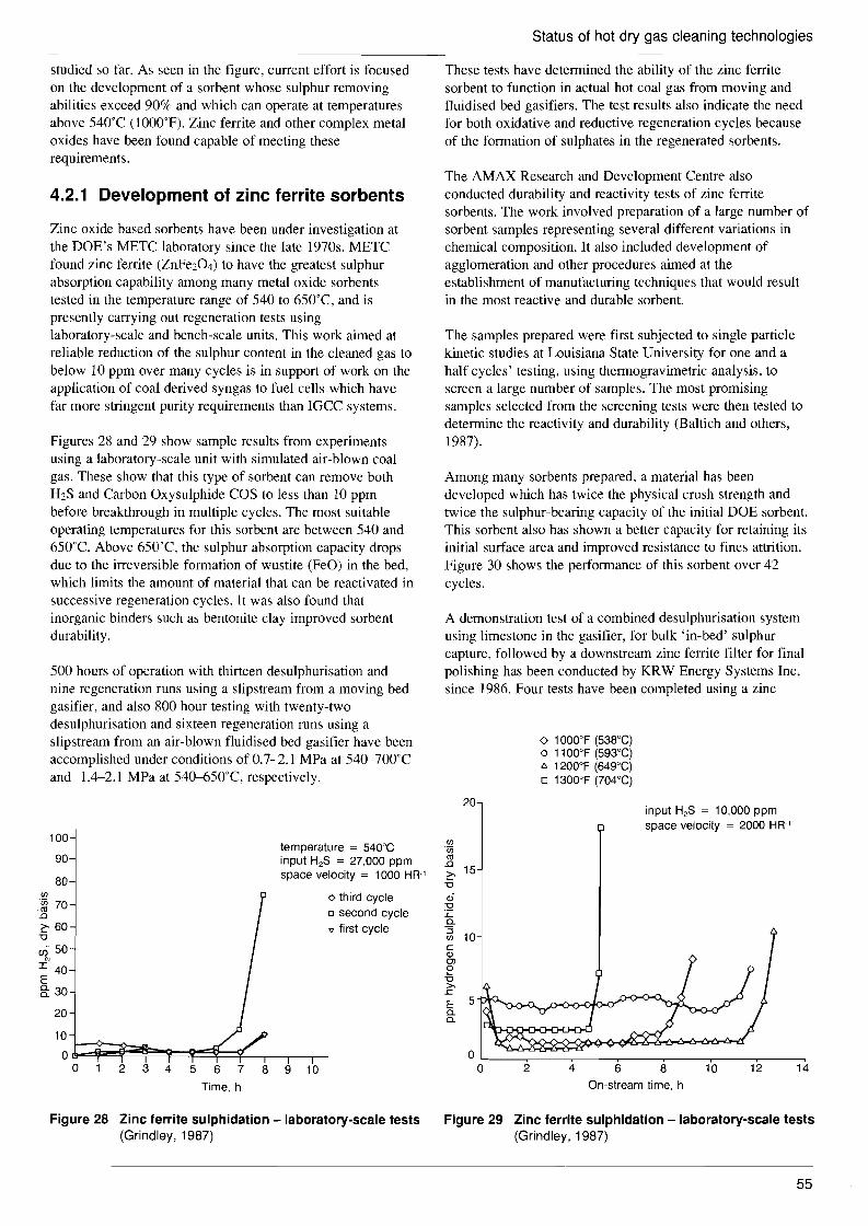
20 input H2S = 10,000 ppm space velocity = 2000 HR-1
(/) "Uj ro .0 ~ 15 -0
<Ii :l2 .r:: 0. "3(/) 10 c QJ OJ o -0 >.
.r:: E 5 0. 0.
2 4 6 128 10 14
Status of hot dry gas cleaning technologies
studied so far. As seen in the figure, current effort is focused on the development of a sorbent whose sulphur removing abilities exceed 90% and which can operate at temperatures above 540T (I OOO°F). Zinc ferrite and other complex metal oxides have been found capable of meeting these requirements.
4.2.1 Development of zinc ferrite sorbents
Zinc oxide based sorbents have been under investigation at the DOE's METC laboratory since the late 1970s. METC found zinc ferrite (ZnFe204) to have the greatest sulphur absorption capability among many metal oxide sorbents tested in the temperature range of 540 to 650T, and is presently carrying out regeneration tests using laboratory-scale and bench-scale units. This work aimed at reliable reduction of the sulphur content in the cleaned gas to below 10 ppm over many cycles is in support of work on the application of coal derived syngas to fuel cells which have far more stringent purity requirements than IGCC systems.
Figures 28 and 29 show sample results from experiments using a laboratory-scale unit with simulated air-blown coal gas. These show that this type of sorbent can remove both H2S and Carbon Oxysulphide COS to less than 10 ppm before breakthrough in multiple cycles. The most suitable operating temperatures for this sorbent are between 540 and 650T. Above 650°C. the sulphur absorption capacity drops due to the irreversible formation of wustite (FeO) in the bed, which limits the amount of material that can be reactivated in successive regeneration cycles. It was also found that inorganic binders such as bentonite clay improved sorbent durability.
500 hours of operation with thirteen desulphurisation and nine regeneration runs using a slipstream from a moving bed gasifier, and also 800 hour testing with twenty-two desulphurisation and sixteen regeneration runs using a slipstream from an air-blown fluidised bed gasifier have been accomplished under conditions of 0.7-2.1 MPa at 540-700°C
These tests have determined the ability of the zinc ferrite sorbent to function in actual hot coal gas from moving and f1uidised bed gasifiers. The test results also indicate the need for both oxidative and reductive regeneration cycles because of the formation of sUlphates in the regenerated sorbents.
The AMAX Research and Development Centre also conducted durability and reactivity tests of zinc ferrite sorbents. The work involved preparation of a large number of sorbent samples representing several different variations in chemical composition. It also included development of agglomeration and other procedures aimed at the establishment of manufacturing techniques that would result in the most reactive and durable sorbent.
The samples prepared were first subjected to single particle kinetic studies at Louisiana State University for one and a half cycles' testing, using thermogravimetric analysis, to screen a large number of samples. The most promising samples selected from the screening tests were then tested to determine the reactivity and durability (Baltich and others, 1987).
Among many sorbents prepared, a material has been developed which has twice the physical crush strength and twice the sulphur-bearing capacity of the initial DOE sorbent. This sorbent also has shown a better capacity for retaining its initial surface area and improved resistance to fines attrition. Figure 30 shows the performance of this sorbent over 42 cycles.
A demonstration test of a combined desulphurisation system using limestone in the gasifier, for bulk 'in-bed' sulphur capture, followed by a downstream zinc ferrite filter for final polishing has been conducted by KRW Energy Systems Inc, since 1986. Four tests have been completed using a zinc
o 1000°F (538°C) o 1100°F (593°C) t:. 1200°F (649°C) o 1300°F (704°C)
On-stream time, h
and
100
90
80 (/)
-~ 70 .0
~ 60 -0
en 50 I 40 E §: 30
20
10
1.4-2.1 MPa at 540-650°C, respectively.
temperature = 540°C input H2S = 27,000 ppm space velocity = 1000 HR-1
o third cycle o second cycle ., first cycle
o~~~~~~h----.----.--o 2 3 4 5 6 7 8 9 10
Time, h
Figure 28 Zinc ferrite sulphidation - laboratory-scale tests Figure 29 Zinc ferrite sulphidation - laboratory-scale tests (Grindley, 1987) (Grindley, 1987)
55

Status of hot dry gas cleaning technologies
Conditions ~ • 10,000 ppm H2 S at inlet I
• outlet 200 ppm at breakthrough
• temperature 650'C 25
• space velocity 2000 hr-1
actual • regeneration between cycles 20
oR0
Oi c 15ii co
..Q
:s 10 .<::: 0:::l
CfJ 5
L-_~_--,_---,__-,-_--._---.__,..--_.-----.0 0 5 10 15 20 25 30 35 40 45
Cycles
Figure 30 AMAX sorbent sulphidation (Voelker, 1987)
ferrite extrusion material manufactured by United Catalysts Inc in a process development unit (PDU) plant at the Waltz Mill research centre. Zinc ferrite pellet material obtained from AMAX is also to be evaluated in the same plant during this programme.
A total of 600 hours of operation, encompassing five desulphurisation and four regeneration cycles, has been accumulated on the external desulphuriser using the United Catalysts' material in two, different sized, fixed bed reactors, one 1370 mm i.d. by 1830 mm long and the other 610 mm by i.d. 1830 mm long. Performance data for the desulphurisation and regeneration are shown in Tables 31 and 32 respectively. In Table 31, the first three runs were
Table 31 PDU desulphurisation performance summary (Smith and others, 1987)
Desulphurisation run 2 3 4 5
Maximum S loading, wt% nla 29 31 nla 19
Radial temp gradient,
°C 153 167 311 56 III Axial temp gradient, °C 42 28 56 39 28
Gas inlet temp, °C 580 565 627 570 588 GHSY, hr I 565 788 794 2800-3600 1900-3300 Superficial velocity, mlmin 3.1 4.7 4.6 J5.2-22.9 11.0-21.9 ~P, MPa 0.01 0.01 0.02-0.050.01-0.04 0.01-0.04 Operating pressure, MPa 1.54 1,45 1.59 1.52 1.31
(H2S+COS) inlet,
ppm 3500 3500 3900 650-1200 800-1300 (H2S+COS) outlet, ppm 11-20 2-10 20-40 54-200 52-200
duration, hours 47 80 116 31 37
nla = not available
Table 32 PDU regeneration performance data (Smith and others, 1987)
Regeneration run 2 3 4
~T rise, °C 42 222 187 194 Inlet gas temperature, °C 579 504 551 538 Pressure, MPa 1.54 1.69 1.59 1.69 02 concentration inlet, vol % 0-0.6 0.8-2.6 1.0-2.6 1.0-2.0 Duration, hours 75 42 144 28
conducted using the larger reactor and runs 4 and 5 were conducted using the smaller reactor. It can be seen that, although the last two runs were conducted with absolute gas flow-rates similar to run 3, some significant differences in performance were observed.
Due to the smaller diameter of the second reactor, superficial velocity, gas hourly space velocity (GHSV) and pressure drop across the bed were all increased. This operating condition resulted in significantly shorter breakthrough times, poorer desulphurisation performance and lower measured sulphur loading on the zinc ferrite after breakthrough occurred (-19 wt%). Sulphur content of the outlet gas and the maximum sulphur loading on the sorbent at the point of breakthrough in runs 1 to 3 were satisfactory.
Three regenerations have been conducted on the larger reactor and one on the smaller reactor. Satisfactory removal of sulphur from the zinc ferrite has been accomplished in every case. Unfortunately there is a tendency for iron sulphate to form in the bed during regeneration, which then releases S02 back into the gas stream during the next desulphurisation cycle. To minimise this effect, the oxygen content of the regeneration gas was reduced to about 2%. Figure 31 shows the concentration of S02 produced by the reduction of iron sulphate to magnetite in the early stage of the desulphurisation cycle. Even if the period of S02 emission into the cleaned gas is short, its concentration is quite high and cannot be neglected.
A pilot-scale plant demonstration of another integrated in situ and external hot gas desulphurisation is planned by Texaco using an entrained flow coal gasification pilot plant, although details of this project are not presently available.
4.2.2 Other metal oxide sorbents
There are various kinds of single metal and mixed metal
1400
1000 E 00- 600 a CfJ 200
ott~~:--,-----,-----,-------,-------,--=~~::<;::2~ o 2 4 6 8 10 12 14 16 18 20 22 24
minutes
Figure 31 502 stack emissions (Smith,1987)
56

Status of hot dry gas cleaning technologies
oxide sorbents under development. Most of the evaluation tests are still conducted in laboratory-scale facilities with one or two exceptions, so that development of these sorbents appears to be at an earlier stage than that of the zinc ferrite sorbents. The objectives set by the US DOE for development of these advanced sorbents are that they should have potential for higher temperature applications and simpler offgas treatment schemes than the zinc ferrite desulphurisation process (Voelker and Halow, 1987).
The mixed metal oxide process being developed by the Institute of Gas Technology (IGT) is one of the more advanced sulphur removal processes. It is based on zinc oxide-on-zinc aluminate and cobalt titanate-on-titania sorbents. The two sorbents are segregated into separate beds as shown in Figure 32. The sulphur-containing fuel gas first comes into contact with the cobalt containing sorbent where more than 67% of the sulphur is removed. The partially desulphurised fuel gas then comes into contact with the sorbent containing zinc oxide where the final sulphur content of the fuel gas is reduced to less than 20 ppm.
desulphurised fuel gas (20 ppm SUlphur)
Zinc oxide sorbent removes the
} residual H2S
cobalt titanate sorbent removes
} the bUlk of the H2S
sulphur-containing 0 fuel gasLI ~~)
Figure 32 Desulphurisation - IGT mixed metal oxide process (Anderson, 1987)
The unique feature of the IGT process is in the regeneration. As shown in Figure 33, the fuel gas sulphur is recovered as elemental sulphur. The regeneration of the mixture is performed with pure 02 and a recirculating stream of S02. The 02 regenerates the zinc oxide-containing sorbent by the reaction:
2ZnS + 302 = 2ZnO + 2S02
The S02 from this reaction is then combined with the recirculating stream of S02 to regenerate the sorbent containing cobalt titanate by the reaction:
2CogSg + 9S02 + 18Ti02 = 18CoTi03 + 25S
The recirculating stream of S02 is required because this reaction is thermodynamically limited. The product gas contains both elemental sulphur and S02. The elemental sulphur is removed from the S02 by cooling and condensation and the S02 is recycled back to the cobalt titanate bed undergoing regeneration.
,--- oxygen
The zinc oxide is regenerated with pure oxygen to produce S02
S02 recycle
The cobalt titanate sorbent is regenerated with S02 to produce elemental sulphur
elemental sulphur
Figure 33 Regeneration - IGT mixed metal oxide process (Anderson, 1987)
Laboratory-scale studies to optimise the concentration of cobalt titanate in the sorbent are under way. Sulphidation testing was conducted using a 20 mm ID fixed bed test system at 650T and 1.7 MPa with a simulated coal gas containing 5000 ppm of H2S. Several cobalt titanate-on-titania sorbents, each with a different cobalt titanate content, were prepared as 4.6 mm diameter by 4.6 mm long pellets from cobalt and titania powders. Regeneration was conducted at 870T and atmospheric pressure with a variety of N2/S02 mixtures. Each sorbent was sulphided and regenerated at least three times.
At an operating space velocity of 2000 hoI, the useful sulphur removal capacity of the 50% cobalt titanate sorbent is about 3.2 kg/45.4 kg (7%) of sorbent, whereas, the useful capacities of the 25% cobalt titanate and 10% cobalt titanate sorbents are about 1.9 kg/45.4 kg (4.2%) and 0.54 kg/45.4 kg (1.2%), respectively.
The evaluation tests of the sorbents are being conducted in a bench-scale system (152 mm i.d., 2720 mm high vessel) using a real coal gas from the 152 mm fluidised bed gasifier located at the IGT Energy Development Centre.
Research Triangle Institute of Research Triangle Park, NC, is also developing advanced mixed metal oxide sorbents to reduce sulphur in coal gas from high temperature fluidised bed coal gasifiers. The emphasis of this project is on testing sorbent formulations which have shown potential for high efficiency hydrogen sulphide removal down to I ppm at sulphidation temperatures greater than 650T. The sorbents which are under testing or to be tested are as follows:
(ZnO)0.86(CUO)0.I4(Fe20 3); (ZnO)0.8(Ti02); (Cu0)3(Fe203)(Ah03); (CuO)(Ah03).
The sorbents are manufactured by United Catalyst Inc,
57
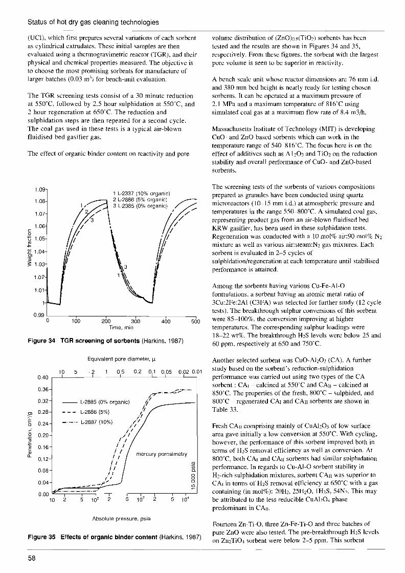
Status of hot dry gas cleaning technologies
(UCI), which first prepares several variations of each sorbent as cylindrical extrudates. These initial samples are then evaluated using a thermogravimetric reactor (TGR), and their physical and chemical properties measured. The objective is to choose the most promising sorbents for manufacture of larger batches (0.03 m3) for bench-unit evaluation.
The TGR screening tests consist of a 30 minute reduction at 550°C, followed by 2.5 hour sulphidation at 550T, and 2 hour regeneration at 650°C. The reduction and sulphidation steps are then repeated for a second cycle. The coal gas used in these tests is a typical air-blown fluidised bed gasifier gas.
The effect of organic binder content on reactivity and pore
1.09 1 L-2337 (10% organic) 2 L-2886 (5% organic) 3 L-2385 (0% organic)
•
\.
~.-1.08 / ./
I /'
1.07 /;//1.06 c o , I t5 1.05 ~ :c 1.04 ~1 OJ 'iii ~ 1.03
1.02
1.01
0.99 '----------,----,----_,- -.---__--, o 100 200 300 400 500
Time, min
Figure 34 TGR screening of sorbents (Harkins, 1987)
Equivalent pore diameter, ~
10 5 ,2 0.5 0.2 0.1 0.05 0.02 0.01 I I I0.40
0.36 .7"'_._.~';'T""_.
.~0.32 -- L-2885 (0% organic) .r.'l
OJ 0.28 - - - L-2886 (5%) .'l~ _._.- L-2887 (10%) /1u 0.24
./
0 C i/
//
0.20 .I' /~
Q) I / c 0.16
i IQ) mercury porosimetry c.. i I0.12 i I ctl
i / '00 n.0.08 ; I o/1 o
0.04 ____ -.r" o to
0.00 10 2 5 102 2 5 103 2 5 104
Absolute pressure, psia
Figure 35 Effects of organic binder content (Harkins, 1987)
58
volume distribution of (ZnO)o.s(Ti02) sorbents has been tested and the results are shown in Figures 34 and 35, respectively. From these figures, the sorbent with the largest pore volume is seen to be superior in reactivity.
A bench-scale unit whose reactor dimensions are 76 mm i.d. and 380 mm bed height is nearly ready for testing chosen sorbents. It can be operated at a maximum pressure of 2.1 MPa and a maximum temperature of 816°C using simulated coal gas at a maximum flow rate of 8.4 m3/h.
Massachusetts Institute of Technology (MIT) is developing CuO- and ZnO-based sorbents which can work in the temperature range of 540-816T. The focus here is on the effect of additives such as Ab03 and Ti02 on the reduction stability and overall performance of CuO- and ZnO-based sorbents.
The screening tests of the sorbents of various compositions prepared as granules have been conducted using quartz microreactors (10-15 mm i.d.) at atmospheric pressure and temperatures in the range 550-800°C. A simulated coal gas, representing product gas from an air-blown fluidised bed KRW gasifier, has been used in these sulphidation tests. Regeneration was conducted with a 10 mol% air:90 mol% N2 mixture as well as various air:steam:N2 gas mixtures. Each sorbent is evaluated in 2-5 cycles of sulphidation/regeneration at each temperature until stabilised performance is attained.
Among the sorbents having various Cu-Fe-AI-O formulations, a sorbent having an atomic metal ratio of 3Cu:2Fe:2Al (C3FA) was selected for further study (12 cycle tests). The breakthrough sulphur conversions of this sorbent were 85-100%, the conversion improving at higher temperatures. The corresponding sulphur loadings were 18-22 wt%. The breakthrough H2S levels were below 25 and 60 ppm, respectively at 650 and 750°C.
Another selected sorbent was CuO-Ah03 (CA). A further study based on the sorbent's reduction-sulphidation performance was carried out using two types of the CA sorbent : CAl - calcined at 550°C and CAn - calcined at 850T. The properties of the fresh, 800°C - sulphided, and 800°C - regenerated CAl and CAn sorbents are shown in Table 33.
Fresh CAll comprising mainly of CuAh03 of low surface area gave initially a low conversion at 550T. With cycling, however, the performance of this sorbent improved both in terms of H2S removal efficiency as well as conversion. At 800T, both CAl and CA" sorbents had similar sulphidation performance. In regards to Cu-Al-O sorbent stability in H2-rich sulphidation mixtures, sorbent CAn was superior to CAl in terms of H2S removal efficiency at 650°C with a gas containing (in mol%): 20H2, 25H20, IH2S, 54N2. This may be attributed to the less reducible CuAh04 phase predominant in CAn.
Fourteen Zn-Ti-O, three Zn-Fe-Ti-O and three batches of pure ZnO were also tested. The pre-breakthrough H2S levels on Zn2Ti04 sorbent were below 2-5 ppm. This sorbent

- ------ - --- - - --
Status of hot dry gas cleaning technologies
Table 33 Properties of CuO.Ab03 sorbents (Flytzani and others, 1987)
CAl CAn sulphided regenerated fresh sulphided regenerated fresh
Surface area, m2/g 98 13
Pore volume, cm3/g 0.39 0.34
Crystallinity, % low low
XRD-phases, wt% CuO CU2S(55) (X-Ah03 y-Ah03(45)
breaks down, at least in part, into ZnO and Ti02. Hence, the ZnO sulphidation properties prevail.
A (ZnO)o.43(Ti02) sorbent which is prepared in the presence of chloride ion (TiCI4) also showed a high reactivity. Sulphur loading was found to be about 10 wt% of the sulphided material.
A solid-supported molten salt (SSMS) system was investigated by Battelle at a bench-scale size. This sorbent consists of porous lithium aluminate ceramic pellets loaded with a low calcium salt. An advantage of the SSMS system is that the sorbent can be regenerated with a carbon dioxide-steam mixture to produce a hydrogen sulphide-rich gas from which elemental sulphur can be efficiently recovered. This sorbent is reported to reduce the concentration of sulphur compounds from 6,000 ppm to less than 1 ppm (Voelker and Halow, 1987).
Although much of the work on advanced metal oxide sorbents is found in the USA, there are developments in other countries. CRIEPI of Japan is testing honeycomb type metal oxide sorbents, as shown in Figure 36 using a bench-scale plant linked with a 2 tid bench-scale gasifier. Two types of honeycomb sorbent based on Fe203 have so far been tested.
Type A Multiple layered silica type honeycomb sorbent;
Type B Titania lattice type honeycomb sorbent.
Seven cycle tests have been conducted on Type A at a desulphurisation pressure of 2.0 MPa and a temperature of 500T, and regeneration temperature of 500T. The target of a pre-breakthrough exit H2S concentration of <100 ppm and a breakthrough time of >2 hours have been successfully achieved while deactivation of the sorbent was not observed during the cycles. This multiple layered type sorbent can operate better at temperatures above 500T. Both desulphurisation and regeneration capabilities of this sorbent decrease below 500T.
Figure 37, shows results of a test on Type B sorbent under the conditions of 400T and 2.0 MPa. It shows that the target is well achieved in cases where inlet H2S concentration was 2000, 1000 and 500 ppm under the
10 5 8 4
0.50 0.36 0.37 0.51
75-80 85 low
CuAh0 4(69) CuAh04(87) Cu2S(71) CuAh04(59) CuAI02 (31) CuO(13) y-Ah03(29) CuO(41)
r----
,.,.,.,.,.,.,.,.,.,.,.,.,.,. ,.,.r,.,.,.,.,.rr,.,.,.,.,.r,.,.,.,.,.,.,.rr,.,.,.,."rr,-,.,.,.,-,.r,.,.,.,.,.,.rr,.,.,.,.,.,.r,.,.,.,-",r,.r,.,.,.,.,.r,.r,.r,.r,.,.,.,.,.,.,.,.,.,.,.,.,.,.,.,-rrrr,-r,-,-,-,-'-'-rJ',.,.,.,.,.,.,.,.,.,.,.,.,.,.,. ,.,.,.,.,.,.,.,.,.,.,.,.,.,.,.r,-,-,-,-r,-rr,.,-,.r,.rr,.,.""",.,.,.,.,.,.,.,.,. ~ fFFFFFFFFFFFFF
,.,.,.,.,. r,.,.,.,.,.,.,.,,.,.,.,.,.,.,.,.,.,.,.,.,.,.,.,.,.,.,.,.,.,.,.,.,.,.,.,.,.,.,.,-,.rrrrrrr,.,rr,r,.,.,.,-rr,-,.,.,.,.,.,.,.,.,.,. ,.,.,-,.,.,.,.,.,,.,.rr,.,.,.,.,.,.,.,.,.,.,.,,.,,.,-,-,.rr,.,.rr,.,,.,"",. ,.,.,.,.,.,.,.,.,.,.,.,.,.,.r,.rrrr,.r,.r,.,r,.,.,. ,.,.r,.,."""",,,,,,,,, r ~~~;:;:~;:~;:::::;::::::::,.,.,.,.,.,.,.,.,.,.,.,.,.,.r,-"",.,.,.rr,.r,.""" ,.,.,.,.,,.,,,,.,,.,,.,. FHfFFFFF~FF~F~
~~r~IJII §~~~~~rnU~r~
........ ,..,.,.,.
Figure 36 Honeycomb type sulphur sorbent
----=
~
'~
(Ishikawa, 1987)
~- - -::~ '"7.:::::..::-•.::::::-0- 0__ --.........~ ........ ..
H2S: 2000 ppm ...... -'!::2~: 500 ppm
gas flow: 400 m3/h "' H2S: 1000 ppm\
temperature: 400°C
pressure: 2.0 MPa
. /
/ /
",/
/ " H2 S: 1000 ppm /
","..... _ -- H2S: 500 ppm •
= -:::::-=" --:::.....
2
100 >Ro
Cii 1) E ~ 90 :s ..c
:sQ.
(J)
80
E100 Q.c: 80 () c o() 60
(J) OJ
:: 40 'x w
20
o o 4 6 8 10 12
Stream time, h
Figure 37 H2S concentration as a function of on-stream time (Ishikawa, 1987)
59

6. porous filter outlet ./
• porour filter inlet~
Status of hot dry gas cleaning technologies
gas volume: 400 m3/h
pressure: 16 atg
temperature: 400°C
o 2 4 6 8 10 12 14 16 18 20 22 24 26 28 30
Time, min
Figure 40 502 content in off-gas regeneration (Cu in alumina system) (Sick, 1987)
The use of copper offers several advantages compared to that of iron. The affinity of metallic copper to sulphur is higher than that of metallic iron, and the affinity for oxygen much lower. Consequently, 10werHzS/Hz ratios can be reached with copper than with iron. at the same temperature. This is particularly so when the gas is less reducing and FeO or Fe304 would be stable and not returned to metallic iron. With regard to the regeneration process, there is the advantage with copper that no sulphate is formed as is the case with
1988).
'"' E 0,
~ .~
Cil c 0 40 ~ c OJ u c 0 u
Cii .c 0
~======:::;::;:::;:;:::;:;::;===:::;;:~~~~~0 0 regeneration desulphurisation
desulphurisation reduction regeneration
R-101
desulphurisation desulphurisation
;:;:.;:;;:,:;.;:;.;,. ....:...:re:.ilg'-=.e=neration reduction
R-102
H2S addition
Test of automatic reactor exchange C
.:!J c o u
(fJ
]! 1000 g c o .~
C target value OJ reactor outlet U C o u
(fJ 100 I 0l.(X>60~~~PQ~~~~~obco6006D0
o 2 3 4 8 9 10 11 12 13
Figure 38 Example of series test results - hot gas cleaning (Watanabe, 1988)
Leybold AG and TV Clausthal in Germany are developing a copper based sorbent, which can work at 750°C for desulphurisation and at 900T for regeneration. The copper is in the form of particles embedded in pellets of alumina. The
E 0, E
i :J o Cil
40c
~ 3-E
OJ
22! o u
1 Cii .c
0.30
0.25
(fJ 0.20I ;oR0
0.15-0 >
0.10
Figure 39
10
'" 5o (fJ
+ o 2 (fJ
?F g
0.5
0.2
conditions of 400°C and 2.0 MPa. At temperatures of 350T and 300°C, the target was also achieved showing that the sorbent operates satisfactorily at comparatively low temperatures such as those at plant start-up. During 13 cycles of desulphurisation and regeneration, no change in the reactivity was observed.
Automatic switching tests using two reactors were also conducted successfully at an interval of 4 hours for sulphiding, with 2 hours for regeneration and 2 hours for reduction. Results from one of these tests are given in Figure 38, which shows both H2S and char concentration at the inlet to and outlet from the filter. A 40 hour test was also conducted in which a combined system of the 2 tid gasifier, a porous ceramic filter and the honeycomb sorbent was operated for 156 hours successfully (Watanabe and others,
sorbent can reduce H2S in a coal gas from 3000 ppm to 300 ppm at 750T in a packed-bed reactor. Regeneration was carried out with air at 900T yielding a gas with about 10% S02 which can be processed into sulphuric acid or elemental sulphur.
Figures 39 and 40 show typical results of desulphurisation and regeneration of the sorbent containing 20% of Cu in alumina (3-5 mm diameter pellets) in a small packed-bed reactor. These show that stable performance has been achieved both in desulphurisation and regeneration cycles, while regeneration time was quite short due, perhaps, to the high temperatures employed.
H2 S starting concentration
750°C 137 cm3min-1
.. cycle 4 66%N2 . 33.7%H2
0
~ } 66%CO. 33.7%H2" • 10
5 6 7 8 g 10 11 12 13 Time, h
H25 content in off-gas during sulphidation (Cu in alumina system) (Sick, 1987)
o "
900°C 180 cm3 min-1
o cycle 6 o cycle 7 " cycle 8 • cycle 9 • cycle 10
60

Status of hot dry gas cleaning technologies
iron, and that the reduction can be performed with a low value reducing gas.
Delft University of Technology of the Netherlands is developing MnO and FeO on y-Ab03 sorbents which have a unique function. The role of y-Ab03 is not restricted to support the metal oxides but acts as an oxidic lattice in which Mn or Fe can be accommodated to form a 'surface spinel' of MeAh04 (when Me =Mn or Fe). The reversible equation for sulphidation and regeneration is considered to be as follows:
The rightward reaction is for sulphidation and the leftward for regeneration. Both reactions can occur at temperatures between 400 and 600T. The main advantage of such a sorbent is that the regeneration takes place without any oxidation. Another most important advantage of this sorbent is that the product of regeneration is H2S rather than S02 and this can easily be converted into elemental sulphur in a plant such as a Claus unit.
A typical breakthrough curve is shown in Figure 41. Almost all H2S is shown to be captured during the first 20 minutes. After about 20 minutes, a sudden breakthrough occurred, and within a few minutes, the outlet concentration of H2S had risen to 30% of the inlet value. The amount of sulphur captured at breakthrough as a function of days on stream is shown in Figure 42.
-H2S,out,%v
approx
10 ppm H2S steep front
o r , o
'breakthrough' ------:..~time
Figure 41 Typical H2S breakthrough curve - Delft system (Soerawidjaja, 1987)
Figure 42 Sulphur captured at breakthrough as a function of time - Delft system (Soerawidjaja, 1987)
The fresh sorbent is shown to capture some 2% of its weight as sulphur. After a week, this decreased to about I% and remained constant at that level for about 80 days, or about 300 cycles.
To a certain extent, this deactivation of the sorbent can be explained by the decrease in surface area. The temperature employed in the test was 600T. If fresh sorbent is used and the temperature is maintained at 400T, little or no deactivation takes place.
In the continued search for low cost sulphur sorbents, attention has been given to waste materials rejected from various industrial processes and other, naturally occurring, materials. Work along these lines has been conducted at the Energy Research Laboratories, CANMET, in Canada. Typical sorbents of this kind studied at CANMET are manganese nodules, and red mud. The chemical composition of these sorbents is shown in Table 34. Both materials contain alkali and transition metals which have been considered active for H2S absorption. Table 35 shows a comparison in performance of various sorbents including manganese nodules and red mud. Calcium doped manganese nodules appear to have potential as a new H2S sorbent capable of operating at temperatures as high as 800T.
Table 34 Chemical composition of manganese nodules and red mud, wt% (Furimsky and Yumura, 1986)
Sample Component MNA MNB RM
Si02 15.0 35.2 12.0
Ah03 4.8 3.0 22.6
Fe203 19.5 50.5 29.7
Mn304 31.8 3.3 CaO 25.9 1.2 4.5
MNA manganese nodule from the floor of an ocean MNB manganese nodule from the floor of a lake RM red mud
Table 35 Performance of absorbents at 800°C· (Furimsky and Yumura, 1986)
Breakthrough Adsorption capacity, Adsorbent time, minutes gH2S/g adsorbent
CaO 15 0.32 ZnO 4 0.25 Fe203 10 0.45 Manganese nodule 18 0.26 Manganese nodule +10% CaO 25 0.32 Red mud 22 0.25
* Results obtained at 0.1 l/min (l0% H2S+N2) using 2 g of adsorbents
4.2.3 Prospects for commercial application
As reviewed above, the development stage of dry and hot H2S sorbents appears to be far behind that of dry and hot dust removal technology. Among the many kinds of sorbents mentioned above, the most advanced stage has been reached with zinc ferrite which is now being tested on a PDU scale
61

Status of hot dry gas cleaning technologies
plant. Another pilot-scale test is planned by Texaco to evaluate this sorbent for application with an entrained flow gasification pilot plant.
To date zinc ferrite has demonstrated higher sulphur loading capacity, lower outlet H2S content and longer breakthrough times compared with other sorbents. It is the most promising material at present, provided the operating temperature is kept below 650T. However, it does have drawbacks such as the production of iron sulphate during the regeneration stage which subsequently releases high concentrations of S02 into the cleaned gas during the early stages of the next desulphurisation cycle.
The formation of iron sulphate can be minimised, although not eliminated, by reducing the oxygen content of the regeneration gas to the lowest level at which regeneration of the sorbent can still be conducted effectively. This tends to make the regeneration operation rather complicated, in that both oxidative and reductive regeneration stages may be necessary.
Another disadvantage of zinc ferrite is that it produces S02 as the offgas during regeneration. In the KRW system, the S02 is recycled to the gasifier where it is ultimately captured by limestone and withdrawn with the ash. It is expected that this system may consume substantial amounts of limestone and produce significant amounts of solid waste, which will then present disposal problems similar to those experienced by PCF power plants with FGD.
Sorbent systems in which S02 is not produced as the offgas are the zinc oxide-on-zinc aluminate/cobalt titanate-on-titania combined system being developed by IGT and MnO or FeO on y-Ah03 sorbent at Delft University. The IGT system had the advantage that the regeneration product was elemental sulphur, although its sulphur loading capacity was only up to about 7 weight% of the sorbent. In the Delft case, the regeneration product was H2S which can be converted into elemental sulphur, without producing any other solid waste, but sulphur loading capacity in this case for the MnO on y-Ah03 sorbent was only 1 or 2% by weight.
The results from testing of the FeO on y-Ah03 sorbent are not available at the moment, although some improvement in sulphur loading capacity is anticipated. It is evident, however, that both systems appear to need more development time before they will be ready for commercial application.
As shown in Table 35, and discussed in previous sections, iron based sorbents demonstrated greater potential in sulphur loading capacity than other sorbents but have the problem of forming iron sulphate during regeneration. The iron based sorbents with high sulphur loading capacities at high temperatures, where zinc ferrite cannot be used, include the CANMET calcium doped manganese nodule sorbent and the 3:2: 1 Cu-Fe-AI-O sorbent at MIT, which produced a sulphur loading capability of 32% by weight at 800T and 18-22% at 750T respectively. Both of these materials appear to have the potential to supplant zinc ferrite for operation at higher temperatures. The CANMET manganese nodule, in particular, appears very promising and full testing to confirm durability of the sorbent is expected.
The copper based sorbents of Leybold AG and TU Clausthal also seem to have potential for high temperature desulphurisation. Although the desulphurisation rate is not high at present, the fact that this sorbent does not form sulphates during regeneration and that it can operate satisfactorily at temperatures up to 900"C are important incentives toward further development. Unfortunately, no sulphur loading capacity data are available.
The honeycomb sorbent produced by CRIEPI has been tested in a PDU scale plant linked with a 2 tid entrained flow gasifier and a similar scale ceramic dust collector. This can be regarded as one of the sorbents at a more advanced stage of development. One of its advantages is that the pressure drop through the bed is low so that it can process large volumes of coal gas. Desulphurisation efficiency of the sorbent is not high at present. Here again further development to improve the efficiency and durability is necessary before it can be given serious consideration for commercial application.
4.3 Ammonia removal In many cases nitrogen contained in coal feed stock is hydrogenated to form ammonia in the raw gas. If ammonia bearing coal gas is burned in a combustion system such as a gas turbine, it tends to form undesirable NOx . Part of this NOx comes from the ammonia in the fuel and the remainder comes from nitrogen in the combustion air. Since nitrogen concentration in coal is generally between 0.5 and 2 weight% of coal, the contribution made by fuel-bound nitrogen cannot be ignored.
In conventional gas cleanup systems based on wet scrubbers, the ammonia, which is soluble in water, can easily be removed from coal gas. However, there has not so far been any commercial or established technology to remove ammonia from coal gas under high temperature, dry conditions. The development of this technology has just been started and the only information available at present is contained in a study of catalysts to decompose ammonia in a coal gas which has been carried out by SRI International, Menlo Park, CA under the sponsorship of the US DOE (Krishnan and others, 1987).
SRI International is preparing various kinds of catalysts containing Nickel, Nickel-Manganese, Nickel-Iridium, Nickel-Copper or Chromium-Cobalt supported on stabilised alumina, magnesium aluminate spinel (monoliths or pellets), silicon carbide fabric and zinc ferrite. Screening tests are conducted for catalyst activity and durability under the conditions of 550 and 800"C at atmospheric pressure using low steam/low H2S simulated coal gas (see Table 36). Detailed kinetic studies on catalysts selected from the screening process are then carried out under the following conditions:
temperatures from 550T to 870T pressures from 0.1 to 3 MPa NH3 levels from 500 to 5000 ppm H2S levels from 0 to 3000 ppm steam levels from 10 to 30 vol%
62

__
Status of hot dry gas cleaning technologies
3000 ppm H2S 100 ppm H2 S1.0Table 36 Composition of simulated coal gas in screening
tests (Krishnan and others, 1987)
Representative gasifier and concentration, mole % ~~~-
KRWair-blown GE air-blown Texaco 02-blown low H20- high IhO- high H20
Component low H2S low H2S high H2S
CO 21.8 7.1 34.5 H2 13.7 15.7 22.0 CO2 7.0 12.4 7.0 N2 39.5 26.5 0.0 H2O 7.2 27.4 28.7 NH3 0.5 0.5 0.5 H2S 0.0001 0.0001 0.3 He* 10.3 10.3 10.3
* He is the diluent in the NH3-He gas mixture used as a source of NH3
Experiments were conducted using a laboratory-scale fixed bed reactor.
Two catalysts have already been tested. The first is a commercial nickel catalyst on magnesium aluminate support designed for methanation and steam reforming of hydrocarbons, up to a temperature of 900T, with superior resistance to steam at high temperatures. Figure 43 shows the performance of this catalyst at 800T. As seen in the figure the catalyst exhibited a high activity without being affected by the presence of steam. The decrease in NH3 removal by adding 100 ppm H2S in the simulated coal gas is due to the competitive absorption of NH3 and H2S on the same active sites of the catalyst. An examination of the catalyst after about 25 minutes of testing at 800T did not show any physical deterioration.
1.0 0 0
0 SV = 1 X 10⁴h ' , BOOae 0 0 0
c 0 27.4% steam, 5000 ppm NH30 0iii ID > c 0 0
(ij 00 c 0.9
"n0
o~ LL o
NoH2 S 100 ppm H2 S.. ·1 O.B '-------,--'-------,-------,----,---.--------i
o 100 200 300 400 500 600
Time, min
Figure 43 Conversion of NH3 by a Ni/Mg.AI203 catalyst at 800°C (Krishnan, 1987)
The second is a nickel catalyst (United Catalysts Inc, G-65) modified by SRI by the addition of 1 wt% Iridium to increase its resistance to H2S poisoning. This catalyst has CaO stabilised alumina as the support. Results from an 800"C test are shown in Figure 44. The Ir-promoted Ni catalyst showed some activity at 550"C (75% without H2S, 55% with 100 ppm H2S) while the commercial one did not. Both catalysts exhibited almost the same high activity at
"1-- ·1 I
r"U"U' oooou I I I
I I
0 I 00...1 I
00000
DOD SV = 1 x 10⁴h1, BOOae I00
27.4% steam, 5000 ppm NH3 1
I 0 100 200 310
Time, min
400 500
Figure 44 Conversion of NH3 by Ir-promo(Krishnan, 1987)
ted Ni catalyst
800T and 100 ppm H2S conditions. It can also be seen that H2S did not act as a poison to this catalyst.
From these results it appears that both catalysts may have a potential to be applied in hot and dry desulphurisation systems. However, further development of other kinds of catalyst are in progress and much better results can be expected in the future.
4.4 Alkali removal As shown in Table 18, the acceptable content of alkali metals in a fuel gas for a gas turbine is limited to 0.05--0.08 ppm to protect the gas turbine blade materials from corrosion. However, little work has been done on removal of alkali metals from high temperature coal gas. Westinghouse R&D Centre, Pittsburgh, PA, is one of the few institutions to have developed the technology to remove sodium from high temperature fuel gas.
The sorbent Westinghouse has chosen is emathlite, a kind of naturally occurring clay. Sodium is collected on emathlite pellets by the formation of glass from sodium vapour combining with the silica in emathlite. The glass is predominantly Na2ShOs which establishes the ultimate collection capacity. In the collection tests using a thermogravimetric analysis unit and a packed-bed bench-scale plant, the following findings were obtained (Bachovchin and others, 1987).
collection kinetics were determined by the rate of diffusion across the product glass layer; kinetics were insensitive to temperature over the range of interest (800-900T); collection rate was proportional to Na concentration; no operational problems such as pellet attrition or bed plugging occurred in the packed-bed tests.
A summary of the fixed bed tests is shown in Table 37. This DOE funded project was completed late in 1986. High temperature potassium removal was left undeveloped. However, if alkali metal removal becomes necessary in a
0.9 c 0 'iii
O.B > ID c 0 0
(ij 0.7 c 0 -~
Cll It 0.6
0.5
63

Status of hot dry gas cleaning technologies
commercial IGee plant, this technology could be applied to the high temperature fuel gas before entering a gas turbine.
Table 37 Summary of fixed bed alkali capture tests (Bachovchin and others, 1987)
Tests 2 3 4 5
Duration, h 102 85 98 46 29.5 Pellet diameter, cm 0.64 0.64 1.27 1.27 0.64
length, cm 1.3 1.3 2.8 2.8 1.3 Bed depth, cm 13 40 40 40 40 Bed area, cm2 314 314 314 314 314 Bed weight, kg 4.0 12.2 11.9 11.8 12.7 Velocity, cm/s 37-43 43-49 38-47 46-47 46-47 Temperature, K 1106-1133 1080-1174 1030-1165 1141-1159 1142-1168 Pressure, kPa 1140-936 1140 1136-1074 1134 1127 Bed ~P, kPa Start 2.9 4.3 3.0 2.7 3.2 Final 58 lOA 3.0 3.9 4.8
NaCl concentration, ppm In 12 10 10 10 10 Out -2 -0.2 0.3-2 0.7-1.1 0.3
Dust feed, g 0 0 696 950 200 Pellet analyses. wt% Na Inlet 4.2 3.1 0.95 Outlet 2.3 0.32 0040
64
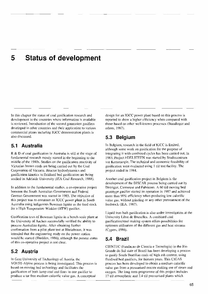
5 Status of development
In this chapter the status of coal gasification research and development in the countries where information is available is reviewed. Introduction of the second generation gasifiers developed in other countries and their application to various commercial plants including IGCC demonstration plants is also discussed.
5.1 Australia R&D of coal gasification in Australia is still at the stage of fundamental research mostly started in the beginning to the middle of the 1980s. Studies on the gasification reactivity of Victorian brown coals are being carried out by the Coal Corporation of Victoria. Reactor hydrodynamics and gasification kinetics in fluidised bed gasification are being studied in Adelaide University (lEA Coal Research, 1988).
In addition to the fundamental studies, a co-operative project between the South Australian Government and Federal German Government was started in 1985. The objective of this project was to construct an IGCC power plant in South Australia using indigenous Bowman lignite as the feed stock for a High Temperature Winkler (HTW) gasifier.
Gasification tests of Bowman lignite in a bench-scale plant at the University of Aachen successfully verified the ability to process Australian lignite. After obtaining further confirmation from a pilot plant test at Rheinbraun, it was intended that the engineering study on the power station would be started (Shedden, 1986), although the present status of this co-operative project is not clear.
5.2 Austria In Graz University of Technology of Austria. the VOEST-Alpine process is being investigated. This process is based on moving bed technology and facilitates the gasification of both lump coal and fines in one gasifier to produce a tar-free medium calorific value gas. A conceptual
design for an IGCC power plant based on this process is reported to show a higher efficiency when compared with those based on other well-known processes (Staudinger and others, 1987).
5.3 Belgium In Belgium, research in the field of rGCC is limited, although some work on gasification for the purpose of integrating it with combined cycles has been carried out. In 1983, Project EDELSTEEN was started by Studiecentrum vor Kernenergie. The technical and economic feasibility of gasification were evaluated using 1 tid test facility. The project ended in 1984.
Another coal gasification project in Belgium is the development of the DISCAR process being carried out by Distrigaz, Carmeuse and Fabricom. A 60 tid moving bed prototype gasifier started its operation in 1987 and achieved more than 90% efficiency when producing low calorific value gas, without grinding or any other pretreatment of the feedstock (lEA, 1987).
Liquid iron bath gasification is also under investigation at the University Libre de Bruxelles. A combined coal gasification/steel making system offers possibilities for optimum utilisation of the different gas and heat streams (Cypres, 1986).
5.4 Brazil CIENTEC (Fundacao de Ciencia e Tecnologia) in the Rio Grande do SuI state of Brazil has been developing a process to gasify South Brazilian coals of high ash content, using fluidised bed gasifiers, for thirteen years. This CIGAS process has been developed to obtain a medium calorific value gas from a pressurised reactor making use of steam and oxygen. The long term programme of this project includes 17 tid atmospheric and 2.4 tid pressurised plants which
65

Status of development
operated from 1984 to 1988, and also a 72 tid pressurised prototype plant for which construction and operation are being projected from 1989 to 1993. Full-scale demonstration plant construction and operation are being projected from 1994 to 1998.
5.5 Canada Some Canadian utilities have shown interest in IGCC power generation and given consideration to evaluation of the most suitable processes to gasify their indigenous coals.
For example. TransAlta Utilities Corporation carried out an evaluation of various coal gasification technologies and their suitability for using Alberta coals under the sponsorship of Alberta/Canada Energy Resources Fund. In this study, Texaco and BG/Lurgi were selected as good candidates for near-term application to 1990, while it was thought that KRW, DOW, Shell and PRENFLO could become viable commercial processes by 1995. Based on the findings and recommendations of the TransAlta study, the Alberta Office of Coal Research and Technology, which is spearheading a National Coal Gasification Technology Research Development and Demonstration Programme, has identified three major objectives for the programme, one of which is to design and build a 150 MW prototype IGCC plant in Canada (Alberta Office of Coal Research and Technology Center, 1988), to be in operation by 1994. The other objectives are to establish and standardise gasification testing methods in Canada and to facilitate evaluation of Canadian coals in various type of gasifier.
Saskatchewan Power has also evaluated IGCC in its Shaunavon Coal Utilisation Study. Phase 1, completed in 1978, concluded that this system would be preferable to either PFB - combined cycle or AFB - steam turbine processes. This utility has chosen the Shell process as the most suitable for gasification of Saskatchewan coals, after a detailed assessment of a number of IGCC alternatives in Phase 2 of the study. A decision on whether to proceed with design and construction of a plant has not yet been made.
A variety of research programmes on lignite and wood gasification have also been carried out by Saskpower Research since 1977. One of the achievements from these programmes was finding catalytic effects of both calcium and sodium in steam gasification of Saskatchewan lignite chars (Weekes, 1980; Van Der Heijden, 1983).
In the maritime provinces there is also interest in IGCC technology, and work is being done to evaluate gasification processes which may be suitable for eastern Canadian coals (Furimsky, 1987).
The Energy Research Centre, CANMET has been involved in hot gas cleanup research aimed at increasing the thennal efficiency of IGCC. The current focus of this work is on screening solid wastes from various industrial processes as possible cheap sources of materials for sulphur sorbents. Calcium doped manganese nodules have been found to have potential as a sulphur sorbent as referred to in Section 4.2.2 (Furimsky and Yumura. 1986; Yumura and Furimsky, 1985;
Furimsky, 1987). The entrained flow plant. which can gasify 5 to 20 kgjh of coal is being used to identify gasification characteristics of Canadian coals under conditions which approach those found in dry feed entrained gasifier.
The University of British Columbia is also involved in both gasification and hot gas cleanup research and is developing a process to remove particulate matter from product gas effectively at elevated temperatures. A spouted bed gasifier of 0.3 m i.d. is used to supply coal gas for testing the efficiency of vortex cyclones and a granular collector. It is also used for gasification performance testing on various Canadian coals (Furimsky. 1987; Watkinson and others, 1987).
The Canadian Coal Gasification Technical Committee has been active since 1987 and been responsible for a number of projects aimed at assessing the suitability of particular technologies for application in Canada. The Canadian Electrical Association also sponsored a study in which performance and cost estimates were prepared for IGCC plants at three different sites across the country, one each in Nova Scotia, Ontario and Alberta. The Coal Association of Canada too has been active in the field and has put forward proposals for a five-year plan leading to construction and operation of a commercial demonstration plant at a host utility.
5.6 China The Chinese Government has a long-term policy to utilise indigenous coal as the major source of energy. During the past two decades, bench-scale, PDU and pilot-scale gasifiers have been built for various kinds of gasification studies. The types of plants built include pressurised moving bed, fluidised bed, turbulent bed, entrained flow and molten bath gasifiers.
In the Beijing Research Institute of Coal Chemistry, development of low-cost, multi-component catalysts for catalytic gasification of coal is being carried out. A 10 tid pressurised moving bed gasifier with a gas cleanup system is in operation for gasification studies at this institute (Flowers, 1986). Commercial application of a second generation gasification process has been planned.
In August 1985, Kellogg Rust Synfuels Inc and the Ministry of Machine Building Industry (MMBI) signed a contract for the construction of a KRW gasifier at the First Heavy Machinery Works (FHMW) in Fulargi. If the performance of this gasifier meets expectations, there is a possibility that existing gasifiers at this site, 25 Russian designed moving bed gasifiers of the first generation, could be replaced with KRW units.
The first gasifier was to be constructed by late 1987 as Phase 1 of the project, in which Kellogg Rust was to provide all basic engineering services including detailed design of the gasifier together with specialised components and instrumentation not available in China. Completion of the detailed design, fabrication, supply and erection of all equipment were allocated to the Chinese participants.
66

Status of development
The first KRW gasifier at Fulargi has a design specification as follows:
Coal feed rate: 249 tid Oxidant: 456 tid (28% 02 enriched air) Steam requirements: 120 tid Pressure: 2.0 MPa Product gas heating value: 5.4 MJ/m3 (LHV)
The gasifier was intended to supply fuel gas to the machinery works (Holmgren, 1985), although these plans have been suspended temporarily because of some re-organisation within the Chinese Government agency that would have been a partner.
Arrangements have also been made for two Texaco gasifiers to be installed. The first is a 400 tid plant to make syngas feedstock for an ammonia plant at the Lunan Fertilizer Company in Shandung Province and is scheduled to commence operation in mid-1990. The second is an 1100 tid plant for the production of fuel gas at the Shougang Iron and Steel Works in Beijing. This unit is planned to enter service in 1991 and feature a radiant boiler for syngas cooling, similar to that which might be applied in IGCC application.
In China, there seem to be no plans at the moment to build a gasifier specifically for the demonstration of IGCC technology for power generation.
5.7 Czechoslovakia In Czechoslovakia, development of innovative gasifiers for commercial town gas production is under way. This work has made use of stationary bed type pressurised oxygen-blown gasifiers having an inside diameter of 2.76 m, with capacities from 5,000 to 12,000 m3jh and has been in progress since 1960. Development of larger and more efficient gasifiers of a similar type is now being pursued. In the past, four gasifiers were exported to Greece and China in 1985 (Jerabek and others, 1987).
No information about specific development of IGCC technology in Czechoslovakia has been forthcoming during this study.
5.8 Denmark There is very little published information available about the R&D of coal gasification in Denmark. One of the two major utility groups in Denmark, Elsam, has been developing plans for an IGCC demonstration unit at Abenra for some time, in association with Preussenelektra in Germany. There seems to be a possibility that others may join the project which will seek funding approval in 1991.
5.9 Finland Atmospheric pressure gasification of biofuels has been the subject of intensive research in Finland. There are several laboratory- and pilot-scale fixed bed and fluidised bed gasifiers in the Laboratory of Fuel Processing and Lubrication Technology of VTT (Valtion Teknillinen
Tutkimuskeskus) in Otamiemi. A pressurised fluidised bed test reactor for coal gasification studies has also been put into operation in Otaniemi.
Beside these government funded research facilities, there are a number of first generation commercial gasifiers in operation. A commercial pressurised fluidised bed oxygen-blown gasifier of the second generation was commissioned at Oulu in April, 1988 by Kemira Oy. This gasification plant is based on the HTW technology. 600 tid dried sod peat are gasified under a pressure of 1.0 MPa and produce synthesis gas for ammonia production.
Recently, interest in IGCC power generation has increased in Finland. A number of decisions about the construction of new power plants based on IGCC technology are expected to be made in the next few years (lEA, 1987; SipiIa and others, 1987).
5.10 France In France. several institutions are carrying out work on coal gasification, although most of them are still in the stage of fundamental study. Among them, Institut de Genie Chimique carries out kinetic studies of steam gasification by means of thermogravimetry using a 150 mm i.d. fluidised bed of hot sand particles. Oxygen-steam gasification is also investigated without sand particles (lEA Coal Research, 1988; Saffer and others. 1985).
Charbonnages de France and IGT/GDC agreed to construct a 200 tid U-Gas demonstration plant at Mazingarbe site in 1983 (Schora and others, 1985). although it is believed that this plan has collapsed because of a decision by the French Government to focus its financial support primarily on developing combustion technologies such as CFBC.
5.11 Germany Germany is well known as the country which invented and commercialised many of the coal gasifiers of the fust generation including Lurgi moving bed. Winkler fluidised bed and the Koppers-Totzek entrained flow systems. It also developed various types of molten bath gasifiers. The fust commercial IGCC power plant at Liinen. using Lurgi gasifiers to provide fuel gas for a combined cycle system featuring KWU gas and steam turbines, as described in Section 2.3.1 was started up in 1972. Superseded by other technology developments, this project was terminated in 1978.
Development work is now directed towards modification of the traditional types of gasifier into second generation systems where high pressure and temperature together with high coal throughput are desirable objectives.
For example, the high pressure PRENFLO system has been developed on the basis of the atmospheric pressure Koppers-Totzek gasifier. A 48 tid PRENFLO demonstration plant was constructed in Furstenhausen and started operation in 1986. A 1000 tid gasifier and 150 MWe commercial IGCC power plant is in the design stage using the engineering data obtained in the operation of the 48 tid plant.
67

Status of development
Similarly, the fluidised bed Winkler process has been developed into the High Temperature Winkler (HTW) system. A demonstration plant of 700 tid capacity was constructed in Berrenrath near Cologne in 1985, and operated at a pressure of 1.0 MPa to produce synthesis gas for methanol production. A pilot plant operating at 2.5 MPa commenced operation in 1989 in oxygen-blown mode and has demonstrated carbon conversion exceeding 90%. From mid-1990 it was intended that the plant would be converted to air blowing. This pilot plant includes ceramic filters for dry gas cleaning. This development is aimed at application of the HTW gasifier to IGCC power generation in order to make lignite-fired power generation environmentally more acceptable.
The Lurgi dry ash gasifiers have been well established for many years. About 170 units have been installed throughout the world including 97 units for synthesis gas production by Sasol, South Africa, and 14 units for SNG production at Great Plains, North Dakota, USA. Lurgi is also developing a new power plant concept in co-operation with BEWAG, one of the utilities in Berlin. At present the c6mpanies are conducting basic engineering for a 180 MW combined heat and power plant with partial gasification in a circulating fluidised bed followed by a second circulating fluidised bed, in a boiler configuration, to bum the residue from the gasifier and a gas cleaning system.
The YEW (Vereinigte Elekrizitatswerke) process uses an entrained flow gasifier and is recognised in Germany as one of the most advanced processes alongside the PRENFLO process. A 240 tid prototype plant has been operated since 1985 at Gersteinwerke near Dortmund. It is different from other entrained flow gasifiers in that coal is only partly gasified with air in this system and the remaining char burned separately. Three different gas cleaning options are being tested which include both wet and dry gas systems. In particular, a novel hot gas cleaning system using a limestone circulating fluidised bed is under development for the removal of halogens from the fuel gas stream before admission to the gas turbine.
MAN and Bergbau-Forschung are planning a pilot plant for steam gasification for integration into a combined cycle power plant. Unlike most other gasifiers in which part of the coal is burned to provide autothermal heating, this process is one of the externally heated, allothermal, processes and uses a long horizontal fluidised bed reactor with minimum back-mixing of ash with the unreacted coal. The expected advantage of this process is considered to lie in the fact that it needs no air separating plant and can be integrated closely with the power generation system.
VEB Gaskombinat Schwarze Pumpe is developing the GSP Process. A demonstration plant was built at VEB in 1983. The aim of this process development is to reduce the dependency on coal quality while increasing the efficiency and productivity of the gasifier.
The GSP gasifier is a top-feed entrained flow slagging gasifier with a water cooled refractory lining. coated with solidified slag. Pulverised lignite, having a particle size less
than 0.2 mm (80% or more), is fed to the gasifier pneumatically. Oxygen and steam are used as oxidants. The throughput of the gasifier is 720 tid, and it is operated under conditions of 3 MPa and 1800-2200T to produce a synthesis gas rich in hydrogen and carbon monoxide. Gasification efficiency is reported to be between 71 % and 73%. On completion of the experimental programme it is planned to use this demonstration plant in commercial operation (Schingnitz, 1987).
Recently, an agreement was made between Deutsche Babcock Werke AG and GSP with its research centre, Brennstoffinstitut Freiberg and plans made for the construction of an IGCC demonstration power plant based on the GSP process with a gross output of about 175 MWe (Rehwinkel and others, 1989)
Much effort in Germany has been devoted to the development of hot gas cleanup systems and gas turbines which can increase the efficiency of power generation. The target of the gas turbine development is to achieve an entry temperature of 1220T and the capacity rating of 200 MW by the beginning of the 1990s. The main development points are improvement of burners and combustion chambers and also the cooling system of turbine blades. A basic and long-term programme for the 'high temperature gas turbine' is being supported by co-operation between about 20 companies and institutes (lEA, 1987).
5.12 India
The Indian Government and Utilities are very much interested in the development of both coal gasification and IGCC technology.
India produces mainly low quality coals containing ash up to 40--45%. There is much interest in finding ways of utilising these low grade fuels.
At the Regional Research Laboratory. Hyderabad, a 24 tid pilot plant using moving bed pressure gasification was commissioned in late 1983. Gasification characteristics of Indian coals have been studied using this plant at different pressures from 1.0 to 2.4 MPa under oxygen/steam-blown conditions. Air/steam blown operation has also been studied at pressures up to 1.0 MPa (Vaidyeswaran, 1987).
The Central Fuel Research Institute in Dhanbad is also carrying out coal gasification studies using a 20 tid moving bed pilot plant. Here, the effects of pressure on carbon conversion and coal throughput have been investigated at pressures up to 3.0 MPa. The prime importance of this study is to make clear whether the high ash coal can be used commercially in high pressure moving bed or entrained flow gasifiers (Juneja and others, 1986).
The first IGCC demonstration plant in India was set up in 1987 by Bharat Heavy Electrical Ltd (BHEL) at the Tiruchy Complex, and was funded completely by BHEL. The gasifier was based on moving bed technology having dimensions of 2700 mm i.d. and 9000 mm height. Coal throughput is 144 tid and the unit accepts sized coal of between 6 and
68

Status of development
30 mm. About 6 MWe of electricity is generated by the plant of which 4 MWe comes from the gas turbine and a further 2.1 MWe from the steam turbine (Rajan, 1987).
5.13 Italy
Italy had two big coal gasification projects which have been supported by the European Community. One of them was the Agip Carbone demonstration plant (200-400 tid) based on the Texaco process to produce syngas from Italian high sulphur coal. The other was a fluidised bed demonstration plant for IGCC application, developed by FIAT TTG and Ansaldo Spa, where the gasification system consisted of two fluidised bed units from Westinghouse Electric Corp operating at 2.0 MPa and 900-1100T. The combined cycle power plant was expected to supply 140 MWe (lEA Coal Research, 1988).
A feasibility study for an IGCC plant has recently been commissioned by Sotacarbo Spa, a joint company of EN!, ENEL, ENEA and the Sardinian Regional Authority. This study is being perfonned by a consortium led by Ansaldo and Snamprogetti Spa and relates to a demonstration plant in Sardinia to use the local, high sulphur, Sulcis coal as main feedstock.
5.14 Japan
An important requirement of coal gasification for Japan is a technology to operate satisfactorily with the widest possible range of coal resources. The strategy for energy security in Japan is to convert every kind of coal and coal liquefaction residue into useful gases. This has a major influence on the types of gasifier chosen for development (Bandou and others, 1987).
The first evaluation study of gasification processes which might be applicable for IGCC power generation was carried out using a 5 tid pressurised fluidised bed PDU plant for several years. Starting in 1974 this work was carried out by JCMR as one of the projects supported by government under the new energy development programme called the Sunshine Project. This initiative was sponsored by MIT! (Ministry of International Trade and Industry). In 1980, a 40 tid pilot plant of the same type was constructed and operated also by JCMR under the sponsorship of NEDO. The plant tenninated its operation in 1987 after accumulating the engineering data necessary for design of a demonstration plant.
A study on entrained flow gasification has also been conducted using a 2 tid PDU scale gasifier by CRIEPI and MHI since 1983.
Based on the evaluation of the results from both types of gasifiers in the light of the above mentioned strategy, MIT! and NEDO decided to support further study of the entrained flow system with hot and dry gas cleanup. Construction of a 200 tid gasifier based on these technologies started in 1987. Mechanical completion is expected in 1990.
This 200 tid gasifier is expected to become one of the most advanced and efficient gasifiers so far developed. It has a dry
coal feed, and is an air-blown, two-stage, slagging entrained flow gasifier. The reactor is comprised of three sections: combustor, diffuser and reductor in sequence from the bottom upwards. Dry powdered coal and air are injected into the combustor tangentially to fonn a spiral flow of gas and solid particles. In the combustor, part of the coal and recycled char from the hot cyclone is burned to produce high temperature gases and char as the first process stage. Further coal and air are then introduced in a similar manner into the diffuser where devolatilisation of the coal takes place utilising the high temperature heat from the combustor. The diffuser is a transition zone between the two stages, where unifonn mixing of reactants also takes place. The main gasification reaction occurs in the reductor which fonns the upper section of the reactor or second stage. Here, product gas is cooled by endothennic reaction and leaves the reactor without further cooling or need for quench gas. The gasifier is to be operated at 1800T in the combustor and a pressure of 3.0 MPa, with carbon conversion and cold gas efficiency expected to reach more than 98% and 78% respectively.
Another 20-50 tid entrained flow gasifier of a similar type is also under construction by NEDO. This is an oxygen-blown gasifier for hydrogen production and will be operated from 1991 at 1.0-3.0 MPa and 1500-1800°C.
Hot and dry particulate and sulphur removal systems have also been developed using the above mentioned three PDU and pilot-scale gasifiers (see Chapter 4). Selected dust collectors and sulphur sorbents are to be tested in both new pilot plants.
Development of high temperature gas turbines is also under way aimed at operation with at least 1300°C inlet temperature. A developed gas turbine is to be installed in an IGCC system based on the 200 tid gasifier (IEA, 1987; CRIEPI, 1986; Bandou and others, 1987).
5.15 Netherlands
In the Netherlands, there were six potential projects to produce coal gas, SNG and electricity during the period 1978 to 1983, but by 1983 all these projects had been cancelled because of low oil prices. Recently, the utility industry in the Netherlands began to pay increasing attention to IGCC power generation after reviewing the excellent achievements of the Cool Water demonstration plant.
Because a major part of the land area already lies below sea level and control of groundwater is so important, environmental considerations, especially acid rain and the international problem of global wanning are major concerns when considering new power generation plants. This is the main reason why IGCC attracted the attention of both government and Samenwerkende Electriciteits Productiebedrijven (SEP). An engineering study on commercial IGCC plants has already been finished together with process and economic evaluations on four different 600 MWe IGCC systems based on Texaco, Shell, BG/Lurgi and PRENFLO.
After a review of these four coal gasification processes
69

Status of development
lasting more than a year, SEP selected Shell technology for the first 250 MWe IGCC plant in the Netherlands in May 1989. The demonstration power station is to be built by SEP's affiliate subsidiary Demkolec BV at the Buggenum site near Roermond, the Netherlands (Clean-Coal, 1989).
In 1985 the government started a national R&D programme aimed at increasing the fundamental knowledge of the use of coal especially for coal gasification and flue gas desulphurisation. The FUGA programme, as it is known, is mainly being carried out by universities and ECN (Energy Research Foundation). A 200 kW moving bed bench-scale gasifier was installed at ECN to test the laboratory results on a more realistic scale. A research programme on low cost, alkali based regenerative sorbents has started at the Technical University of Twente, in association with other universities in Greece and Portugal, under the European Community Joule programme.
An industrial programme is also being carried out by industrial sectors at Shell and KEMA. KEMA is involved in the design of a 225 MWe IGCC plant with Texaco gasifiers (2 x 850 tid). A decision to construct this plant was to be taken in 1988 (lEA, 1987; Booij, 1987), although, with SEP's decision to choose the Shell gasifier, this programme seems to have been suspended.
5.16 Portugal
The interest and activity in coal gasification R&D in Portugal is generally low. Among the few institutions engaged in coal research, the Department of Conventional Energy is currently working on gasification of coal with steam in the absence of air, by encouraging pyrolytic reaction, using a fluidised bed reactor operated under atmospheric pressure at about 1000°C. The reactor is to be operated at elevated pressure in the future (Gulyurtlu, 1987).
5.17 South Africa
It is well known that SASOL of South Africa produces motor fuel from coal by means of coal gasification and Fischer-Tropsch synthesis. SASOL has constructed 97 Lurgi dry ash gasifiers of which the 36 oldest units at SASOL-l began commercial operation in 1980. Now the whole system at SASOL consumes about 100,000 tonnes of coal a day.
There is no information about development of any specific IGCC technology in South Africa. Development of a fluidised bed gasifier for processing duff and other coal discards, in order to recover usable energy and reduce wastage, is being carried out (Bonapace, 1987).
5.18 Spain
Since OCIDE and OCICARBON were established in 1983 and 1985, as the managing associations for research and development of electricity and coal respectively, the interest in coal gasification as a clean use of coal and an effective way of power generation has increased markedly in Spain. Both organisations started financing research projects just
after they had been established, with laboratory-scale plants on atmospheric fluidised bed gasification.
In the industrial sector, Fuentes de Ebro has a pilot plant to gasify powder pellets of lignite in operation, which produces mixed gas having a calorific value of 4.8-5.6 MJ/m3 for industrial applications.
For combined cycle power generation, Hidroelectrica Espanola, SA has started a study relating to the Lada plant as one of the OCIDE programmes financed by The European Community and the Spanish Electric Utility Research Programme. At this stage of the project, Hidroelectrica Espanola is working in collaboration with Krupp-Koppers and Empresarios Agrupados, a Spanish engineering company (lEA, 1987).
At the University Politecnica de Catalunya, atmospheric fluidised bed gasification is also being studied. On the basis of the experience at atmospheric pressure, high pressure operation will be evaluated in future studies. A small-scale plant for this purpose is under construction (Arnaldos and others, 1987).
5.19 Sweden
A 12 tid fluidised bed MINO-PILOT plant was operated in the early 1980s at Studvik. This project developed a high pressure process for the production of synthesis gas from wood, peat or brown coal. The next step of this project is to adapt the process to combine gas and steam turbine cycles to generate electricity (lEA Coal Research, 1988).
A demonstration plant of the MIP (Molten Iron Puregas) process developed by KHD Humboldt Wedag Ag and Sumitomo Metal Industries Ltd, has been in operation to produce low sulphur fuel gas and synthesis gas from coal at MEFOS in Lulea, Sweden since 1985 (Henrich and others, 1984).
Utilities in Sweden have an interest in IGCC power generation and both Vattenfall and Sydkraft are studying the possibility of introducing gasification systems for IGCC power plants, in the foreseeable future.
5.20 United Kingdom
Coal gasification R&D in the UK is represented mainly by the British Gas BG/Lurgi process and the fluidised bed gasifier being developed by British Coal.
British Gas started its pilot plant development work on a slagging version of the moving bed gasifier in the early 1960s at the Midlands Research Station, Solihull, using a 1 m diameter reactor. Collaboration with Lurgi started in 1975.
The first demonstration plant was established at Westfield, Scotland by conversion of an existing dry bottom gasifier for slagging operations at a throughput of 320 tid. This plant gasified 91,000 tonnes of coal during 377 days of operation. A 90-day run was carried out which consumed 27,500 tonnes
70

Status of development
of coal and achieved stable operation over the range of 30% to 110% load with no significant change in gas quality. Amongst other things, operation of this plant verified the capability to operate with coal fines content up to 40% of the total throughput and the ability to handle caking coals satisfactorily.
A 500 tid demonstration plant was constructed in 1984 and this too has demonstrated excellent operating stability over a 25% to 110% load range. A two-month operation of the gasifier combined with the Hi CoM methanation plant was successfully completed, after consuming more than 18,000 tonnes of UK and US coals, early in 1989 (British Gas, 1989).
Although the British development is aimed primarily at the production of pipeline gas, the suitability of the BG/Lurgi gasifier for combined cycle power generation system has also been demonstrated by trials at Westfield. The 500 tid plant has been used to supply fuel gas to a Rolls Royce SK-30 gas turbine, which has been installed on site. Results of this work have shown the suitability of this gasifier for combined cycle application (Lacey, 1984). During the two-month trial mentioned above the SK-30 gas turbine was in operation and 27 MWe power was exported to the national grid (British Gas, 1989).
British Coal and Otto-Simon Carves Ltd (OSC) have been co-operating to develop a fluidised bed gasification process to produce fuel gas for furnaces, kilns and other industrial applications.
A 12 tid gasifier was constructed at The Coal Research Establishment (CRE) in Cheltenham, England in 1985. CRE has used this plant to confirm the technical and economic viability of the process, and plans to continue development of this technology in order to provide an alternative for eventual replacement of more expensive fuels in a wide range of industrial processes in the future. Work is also proceeding on a high pressure partial gasifier to provide fuel gas for a hybrid, IGCC/FBC system which British Coal has designated as its Topping Cycle project.
OSC has designed three standard plant models, 1.5 t/h, 2.5 t/h and 4 t/h. Those plants are now being offered commercially worldwide (Smith, 1986).
5.21 United States of America
The world's first commercial IGCC plant using an entrained flow gasifier, at Cool Water in California, commenced operation in 1984 and successfully completed its planned programme in 1989. This project was based on the Texaco gasification process and was run to evaluate the superior capability of an IGCC system to meet stringent environmental standards. The Cool Water plant achieved more than 97% reduction of S02 emission, substantially below the level allowed by US EPA New Source Performance Standards (NSPS). It also reduced NOx emissions to 10% of the standards (lEA, 1987; Watts and others, 1987).
Two other second generation entrained flow gasifiers, based
on the DOW Syngas Process and Shell Coal Gasification Process, started demonstration operation in April and July 1987, respectively. The DOW system had logged 1752 hours on stream by 17 of October 1987, while the Shell unit logged 3636 hours on stream including a continuous operation of 1500 hours by 11 May 1988 (Coal and Synfuels, 1987; Modem Power Systems, 1988; Clean Coal, 1988).
The DOW gasifier can process 2200 tonnes of coal a day and currently is the largest single unit coal gasifier operating in the world.
In 1987, the US DOE selected two IGCC projects from proposals submitted in response to its first solicitation under the Clean Coal I Technology Demonstration Programme.
One was the 'Magic' project proposed by Consolidation Coal Company and Foster Wheeler Power Corporation. This system was designed to convert approximately 450 tid of high sulphur West Virginia coal into electric power (30 MWe) and steam (91 t/h, 1.7 MPa, 290T). It was intended that the steam produced would be used in the buildings and laboratories of West Virginia University in Morgantown, replacing three obsolete coal-fired boiler plants, while the power would be sold to the Monongahela Power Company. The proposed system was based on the U-Gas coal gasification process with direct desulphurisation in the gasifier using limestone. Downstream hot gas cleaning with ceramic filterslzinc ferrite hot gas cleanup system was included in this proposal (lEA, 1987; Clean coal, 1988).
The second project was called the Appalachian project proposed by Kellogg in association with General Electric Co. It was aimed at IGCC power generation using Appalachian bituminous coal at a rate of 440 tid in an air-blown fluidised bed KRW gasifier to provide fuel gas for a MS 6001 gas turbine. Here again, direct desulphurisation with limestone in the gasifier and downstream hot gas cleaning using ceramic candle filters and zinc ferrite were proposed (lEA, 1987). Licensing difficulties and other commercial problems have caused this project to be dropped from the Clean Coal I programme.
Texaco has arranged to purchase the Cool Water facility and continue its operation as an independent power producer. The plant is to be converted to gasify a mixed feed of coal and sewage sludge. Product power will be sold to the local utility. Two other joint venture projects, using Texaco technology, are also in the planning stage. The first is the Delaware Clean Energy Project, which will make use of petroleum coke from a local refinery. The second is the Freetown Energy Project in Massachusetts, based on coal utilisation, which is rated at 440 MWe and due to enter service in 1994.
The US DOE has been promoting the development of advanced coal gasification and hot gas cleanup systems under its own R&D programmes. Several contractors and the Morgantown Energy Technology Centre (METC) are involved in these programmes which include work on the fixed bed gasification process (22-44 tid) at METC, and hot and dry gas cleanup applied to both the KRW fluidised bed
71

Status of development
(14-27 tid) and the Texaco entrained flow (14-23 tid) gasifiers all with in-bed desulphurisation and external gas polishing using zinc ferrite, to reduce sulphur emissions below 10 ppm.
Advanced particulate control techniques and novel sulphur removal technologies have also received attention under the DOE's GSCU programmes as described in Section 4.1.
As reviewed above, the activity of the US Government in both internal programmes and sponsorship of jointly funded projects in the private sector to develop efficient gasification systems and IGCC power plants is quite high. Especially strong is the will to achieve a clean environment and much attention is being given to improved techniques for gas cleaning.
5.22 Other countries
In other countries such as Mexico, Colombia, Chile, Greece and Israel, coal gasification R&D is known to be under way. However, almost no information has been obtained so far about these countries.
The situation is the same for Eastern European countries, including the USSR and Poland, where R&D is believed to be carried out actively.
5.23 Commentary
As reviewed above, there are many countries with interests in IGCC power generation. Among them, some are developing their own technologies and some are thinking of introducing
foreign technologies, although the latter countries at present seem to be hesitating to press ahead with IGCC systems. This can be attributed to the present situation where the Cool Water plant is the only recent example of the commercialisation of IGCC technology. Although it has shown excellent environmental acceptability, so far it has not shown any superiority in operating efficiency over conventional PCF power plant operating with super-critical steam conditions and using FGD to meet environmental standards.
Apart from technological considerations discussed in this report, a fresh approach to the management of intellectual property rights also seems necessary. Most gasification and gas cleaning technology has developed in the chemical process industry, where system developers traditionally maintain tight control over their design and operating data while manufacturers hold patent protection for particular equipment items. In the case of utilities, however, while manufacturers of boilers, turbogenerators and other items similarly hold patent protection, the overall system design is usually the property of the user utility, which sees little reason to seek protection from competitors in this area.
Consequently, the notion of secrecy agreements relating to transfer of essential system data between suppliers of technology designers and potential end-users, which is common practice in the process industry, is somewhat alien to utilities. A clear opportunity exists for a means to overcome this difference in philosophy such that chemical process technology, which will be of increasing importance in meeting environmental and other criteria, may be assimilated more quickly and easily by utilities.
72

6 Conclusions
Representative coal gasification processes are ready for application to IGCC power generation in utility service. The main incentive for utilities to adopt this technology seems likely to be stringent environmental requirements. Well proven commercial gas processing options are available with capability to clean fuel gases to almost any desired standard. In many cases there is scope for further development to improve efficiencies in the gasification step, reduce energy losses from the cleaning stage and optimise the whole IGCC system.
Coal gasification for electric power generation is not a new concept. Early efforts were related to the invention of the internal combustion engine. Development continued in parallel with steam based systems until the appearance of the steam turbine led to virtual eclipse of gasification from this field. In recent years, the arrival of large reliable combustion turbines, and the opportunity to develop combined cycle systems with steam turbines for enhanced overall cycle efficiency, has resulted in renewed interest in coal gasification for utility power generation.
Because of the complexity of these systems, comparative evaluation of performance can be difficult. A simplified approach has been developed here which permits plants to be evaluated in terms of five main elements. Use of this system helps to focus attention on those areas of the plant which contribute most to differences between systems. This approach introduced the concept of heat by-pass, as a separate entity to describe energy which is released from the fuel and passed directly to the steam cycle. It is often found desirable to design for the lowest possible heat by-pass in order to obtain maximum overall cycle efficiency.
Heat by-pass usually arises from waste heat recovery associated with temperature control requirements in the gas processing stream, such as cooling of gasifier walls and temperature adjustments at the inlet to scrubbing systems.
Hot wall operation of the gasifier and hot, dry gas cleaning represent major countermeasures to reduce heat by-pass.
Other factors affecting gasification efficiency are the nature of the feed and choice of oxidant. From a performance viewpoint, there are advantages to using dry coal feed and air as oxidant. Dry coal feed is used in several systems and work is in progress to tailor the design of air separation systems to the special requirements for oxygen production in IGCC applications. This includes close integration into the system which shows promise of offsetting the apparent advantage of air-blown gasifiers.
Development of any gasification system was usually undertaken in the first instance to meet a particular requirement. Despite considerable effort on the part of the developers to broaden the application of their systems, identifiable characteristics from the original concept often are retained. This means that different processes can have particular attributes which may be more appropriate in specific applications. All processes may not be equally applicable in any situation.
Three large-scale demonstration plants have been built and operated while others are now under construction. Valuable lessons have been learned from the plants at Liinen (1972), Cool Water (1984) and Plaquemine (1987). A new plant, based on Shell technology is under construction at Buggenum in the Netherlands.
The Lurgi system has a long history of development and commercial application, including an IGCC demonstration in air-blown mode at Liinen. This gasifier tends to be somewhat selective with regard to size and quality of the coal feed although the British Gas/Lurgi slagging system has been demonstrated satisfactorily on a wide range of coals. This system demonstrates the highest cold gas efficiency among those considered here, probably because it was developed primarily for the manufacture of pipeline gas.
73

Conclusions
The Texaco system has been widely used for oil gasification and several commercial coal gasification examples are in operation for the production of synthesis gas for the manufacture of chemicals. There is a substantial background of operating experience for this system with stringent gas cleaning in large industrial applications. It too has been demonstrated in an IGCC application, in oxygen-blown mode, at Cool Water.
The Dow system was primarily developed for the conversion of lignite and uses two stage coal injection to take advantage of the reactivity of this fuel. The only installation is operating in a commercial scale IGCC system at Plaquemine. Work is now in progress to evaluate and demonstrate operation of this unit on a wider range of coals.
Both the Shell and PRENFLO systems are high pressure developments from the Koppers Totzek system, which operates at near atmospheric pressure and has been used quite widely in commercial applications. These new pressurised units are of sophisticated design and both have given promising results in tests on a wide variety of coals in experimental facilities.
Fluidised bed gasifiers tend to have lower carbon conversion than other types due to unavoidable carry-over with the ash. This shortcoming can be overcome by the addition of a carbon bum-up stage, usually a boiler for steam raising, which presents a special case of heat by-pass. Unlike the temperature control cases mentioned earlier, heat by-pass
here is in the form of potential heat which leaves greater scope for optimisation of the steam cycle. Minimising the by-pass is less critical in these cases.
While considerable development effort is being applied to hot gas cleaning, the greatest progress has been made with particulate removal systems, which have reached the demonstration stage. The main effort is currently directed toward sulphur removal under high temperature dry conditions. In this case, zinc ferrite sorbents look promising but have not yet reached such an advanced stage as particulate filters. Still less well developed are systems for the control of ammonia, to limit availability of nitrogen for eventual release as NOx , and capture of alkali metals to protect the turbine blades and avoid fugitive emissions.
A review of activities around the world showed that more than twenty countries have active Research and Development projects associated with IGCC applications and several have plans for the construction of demonstration plants in the near term.
The approach to protection of commercial property rights shows marked differences between normal practice in the chemical process industry and that customary to utilities. In particular, secrecy agreements which are widely used in the process industries are not readily acceptable to utilities. Improved interchange of information between potential participants is required to facilitate more rapid implementation of these technologies in utility service.
74

Appendix: Status of demonstration and commercial plants
Gasifier Project Location Coal Product Start-up or company throughput, (final)
tonnes/day
2nd generation gasification plants in commercial operation
Texaco Tennessee Eastman Tennessee, USA 820 methanol 1983 Texaco Cool Water California, USA 910 IGCC 1984 Texaco Ube Industry Ube, Japan 1500 ammonia 1984 Texaco Ruhrkohle/Ruhrchemi Oberhausen, FRG 1720 Oxo chemicals 1986 HTW KemiraOy Oulu, Finland 600 ammonia 1988
2nd generation gasification plants in demonstration operation
Ruhr 100 Ruhrgas FRG 100-200 fuel & synthesis 1979 BG/Lurgi British Gas Westfield, UK 500 fuel & synthesis 1984 Kiln Gas Allis-Chalmers Illinois, USA 540 fuel gas 1983 U-Gas IGT Chicago, USA 27 fuel & synthesis 1974 KRW Kellog-Rust-Westinghouse Pennsylvania, USA 14-27 fuel gas 1975 HTW Rheinbraun Berrenrath, FRG 720 methanol 1985 VEW VEW Dortmund, FRG 240 fuel & synthesis 1985 PRENFLO Koppers-Totzek Furstenhausen, FRG 48 fuel & synthesis 1986 Shell Shell Texas, USA 230-360 fuel & synthesis 1987 Dow Dow Louisiana, USA 2200 IGCC 1987 Saarberg-Otto Saarberg-Otto Furstenhausen, FRG 260 fuel & synthesis 1979 MIP Humboldt/Sumitomo Lulea, Sweden 240 fuel & synthesis 1986
(MEFOS)
2nd generation gasification plants under construction or planned
NEDO NEDO Chiba, Japan 20-50 hydrogen 1991 NEDO NEDO Iwaki, Japan 200 IGCC 1991 KRW Appalachian project Pennsylvania, USA 440 IGCC 1990 U-Gas CCC-FWPSC Virginia, USA 450 IGCC 1990
75

References
Alberta Office of Coal Research and Technology Centre (1988) Gasification of Western Canadian Coals. Alberton, AB, Canada, Alberta Energy, Scientific and Engineering Services and Research Division, (1988) Anderson G L, Berry F 0 (1987) Development of a hot gas clean-up system. In: Proceedings of the seventh annual gasification and gas stream clean-up systems contractors review meeting. M R Ghate, K E Jr Markel, L A Jarr, S J Bossart (eds). Morgantown, WV, USA, 16 Jun 1987, DOE/METC-87/6079-VoI2, Palo Alto, CA, USA, Electric Power Research Institute, Nuclear Power Division, pp 642-655 (Aug 1987) Arnaldos J, Casal J, Coli T, L10p M, Puigjaner L (1987) Effects of pressure on fluidised-bed coal gasifiers. Paper presented at the seventh conferencia sobre planificacion, ahorro y alternativas energeticas, Zaragoza, Spain, Oct 1987, vp (1987) Bachovchin D M, Alvin M A, Day L M (1987) A study of high temperature removal of Alkalima pressurised gasification system. In: Proceedings of the seventh annual gasification and gas stream clean-up systems contractors review meeting. M R Ghate, K E Markel, L A Jarr, S J Bossart (eds). Morgantown, WV, USA, 16 Jun 1987, DOE/METC-87/6079-Vol 2, Palo Alto, CA, USA, Electric Power Research Institute, Nuclear Power Division, pp 495-504 (Aug 1987) Baltich L K, Berggren M H, Harrison D P (1987) Enchanced durability and reactivity for zinc ferrite desulphurisation sorbent. In: Proceedings of the seventh annual gasification and gas stream clean-up systems contractors review meeting. M R Ghate, K E Markel, L A Jarr, S J Bossart (eds). Morgantown, WV, USA, 16 Jun 1987, DOE/METC-87/.6079 - Vol 2, Palo Alto, CA, USA, Electric Power Research Institute, Nuclear Power Division, pp 693-703 (Aug 1987) Balzhiser R E, Yaeger K E (1987) Coal fired power plants for the future. Scientific American; 257 (3); 92-99 (1987) Bandou S, Furuya K, Ameniya K, Ishikawa H, Hona K, Ogawa K (1987) Outline of a 200 t/d coal gasification
combined cycle pilot plant. In: Proceedings of the international conference on advanced coal power technology and hot gas cleaning. Dusseldorf, Federal Republic of Germany, 2-4 Dec 1987, FGD V34, Palo Alto, CA, USA, Electric Power Research Institute, (1987) Baron R E, Porter J H, Hammond 0 H (1975) Composition vs temperature plots. In: Chemical equillibria in carbon-hydrogen-oxygen systems. London, UK, The MIT Press, pp 30 (1975) Bonapace A C (1987) Duff and coal discards in South Africa; their utilisation as a beneficiated fuel by a fluidised-bed gasification process. South African Mining World; 6 (8); 78-81 (Sep 1987) Booij M (1987) Fundamental coal gasification research (FUGA): interim report 1985-1987. Utrecht, the Netherlands, Management Office for Energy Research (PEO), 52 pp (1987) Brame J S S, King J G (1955) Producer gas. In: Fuel, solid, liquid and gaseous. London, UK, Edward Arnold, pp 410-411 (1955) British Gas press information (1989) British Gas demonstrates successful integrated gas making process at Westfield. British Gas press information; (26 Jun 1989) British Petroleum Company, Government and public affairs department (1987) Stastistical review of world energy. British Petroleum; 37 (lun 1987) CRIEPI (Central Research Institute of Electric Power Industries) (1986) The realisation of coal gasification combined cycle power generation. Denken review; 15; vp (lun 1986) Ciliberti D F, Lippert T E (1986) Ceramic cross flow filters for hot gas cleaning. In: Proceedings of the transactions of the Institution of Chemical Engineering symposium. Guildford, UK, 16-18 Sep 1986, Rugby, UK, Institution of Chemical Engineers, pp 193-213 (1986) Clark E (1988) Cool water coal gasification programme an update. EPRI Journal; 13 (6); 45-48 (1988) Clean-Coal, Synfuels letter (1988) Shell completes gasification demonstration. Clean-Coal/Synfuels letter; 2-3 (3 Jun 1988)
76

References
Clean-Coal, Synfuels Letter (1989) Dutch utility chooses Shell IGCC process for 250 MW coal gasification plant. Clean-Coal/Synfuels Letter; (22 May 1989) Coal and Synfuels Technology (1987a) Clean coal project to test advanced IGCe. Coal and Synfuels Technology; 8; 6 (26 Oct 1987) Coal and Synfuels Technology (1987b) Good year for IGCC tests. Coal and Synfuels Technology; 8; 6-8 (2 Nov 1987) Coal and Synfuels Technology (1989) IGCC units planned in Denmark. Coal and Synfuels Technology; 10 (17); (1 May 1989) Conkle H N (1987) Development of a novel nested-fiber filter concept for high temperature and high pressure physical clean-up. In: Proceedings of the seventh annual gasification and gas steam clean-up systems contractors review meeting. M R Ghate, K E Markel, L A Jarr, S J Bossart (eds). Morgantown, WV, USA, 16 Jun 1987, DOE/METC-87/6079 - Vol 2, Palo Alto, CA, USA, Electric Power Research Institute, Nuclear Power Division, pp 610-613 (Aug 1987) Cool water coal gasification (1986) Cool Water coal gasification programme. EPRI-AP-4832, Palo Alto, CA, USA, Electric Power Research Institute, 224 pp (Oct 1986) Cornett M S (1987) Process improvements makes integrated gasification combined cycle viable. Modern Power Systems; 7 (10); 25-31 (Oct 1987) Curran P F (1987) Clean power at cool water. Mechanical Engineering; 109 (8); 68-71 (Aug 1987) Cypres R (1986) Modern carbochemical processes for hydrogen production from coal. In: Proceedings of the Beijing international symposium on hydrogen systems. TN Veziroglu, Y Zhu, D Bao. Beijing, China, 7 May 1985, Elmsford, NY, USA, Pergamon Press, pp 25-38 (1986) Dawkins R P, Hughes M K, Lamprecht D G, Rao A D, Sander M T (1985) Cost and performance of Kellogg Rust Westinghouse based gasification combined cycle plant. In: EPRI Research Project. AP-40l8 2029-4, Palo Alto, CA, USA, Energy Power Research Institute, vp (1985) Dorstewitz U, Wien H (1980) Die KDV-Anlage L(lnen. In: Proceedings ofYGB conference on Kohlevergasung in del' Energietechnik. Dortmund, Federal Republic of Germany, 27-28 Mar 1979, Essen, Federal Republic of Germany, VGB Technische Vereinigung der Grosskraftwerksbetreiber eV, pp 135-173 (1980) Elliott M (1981) Coal gasification processes. In: Chemistry of coal utilization-second supplementary volume. New York, USA, John Wiley & Sons, pp 1608-1611 (1981) Engelhard J, Adlhock W (1988) The high temperature Winkler process operational experience and new development. Paper presented at the eighth EPRI coal gasification contractor's conference, Palo Alto, CA, USA, 19-20 Oct 1988, vp (1988) Engelhard J, Femmer U, Adlhock W (1987) The Rheinbraun high temperature Winkler demonstration plant for synthesis gas production: construction and start-up. In: Proceedings of the sixth annual EPRI contractor's conference on coal gasification. Palo Alto, CA, USA, 15-16 Oct 1986, AP-5343-SR, Palo Alto, CA, USA, Electric Power Research Institute, pp 10.1-10.26 (Oct 1987) Femmer U, Lambertz J, Theis K A (1987) Gasification of brown coal for the generation of synthesis gas. Energy Progress; 7 (3); 130-133 (Sep 1987)
Firestone R F, Kennedy C R, Greaves M J (1981) Refractory liners for slagging coal gasifiers. Papers presented at the 1981 international gas research conference, Los Angeles, CA, USA, 28 Sep-l Oct 1981, pp 480-490 (1981) Fisackerly R H, Sundstrom D G (1987) The DOW syngas project; description and status report. In: Proceedings of the fourteenth biennial lignite symposium on the technology and utilisation of low-rank coals. Dallas, TX, USA, 19 May 1987, Grand Forks, ND, USA, North Dakota University, pp l.B3-1.B312. (1987) Flowers A B (1986) Coal Gasification in China. Paper presented at the Alternate energy '86 worldwide trends & prospects in synthesis fuels and clean coal technologies, Captiva Island, FL, USA, 18-21 May 1986,9 pp (1986) Flytzani-Stephanopoulos M, Jothimurugesan K, Lew S, Gavalas G R, Patrick V (1987) Detailed studies of novel regenerable sorbents for high temperature coal-gas desulphurisation. In: Proceedings of the seventh annual gasification and gas stream clean-up systems contractors review meeting. M R Ghate, K E Markel, L A Jarr, S J Bossart (eds). Morgantown, WV, USA, 16 Jun 1987, DOE/METC-87/6079 - Vol 2, Palo Alto, CA, USA, Electric Power Research Institute, Nuclear Power Division, pp 726-740 (Aug 1987) Furimsky E (1987) Ottawa, Oregon, Canada, Energy Research Laboratories, Private communication (Oct 1987) Furimsky E, Yumura M (1986) Solid adsorbents for removal of hydrogen sulphide from hot gas. Erdol und Kohle - Erdgas - Petrochemie vereinigt mit Brennstoff-Chemie; 39 (4); 163-172 (1986) Garside P G (1986) KILnGAS process for producing clean gas from high-sulphur coal; major technical accomplishment and plans. Energy Progress; 6 (1); 5-11 (1986) Grindley T (1987) Sidestream zinc ferrite regeneration testing. In: Proceedings of the seventh annual gasification and gas stream systems contractors review meeting. M R Ghate, K E Markel, L A Jarr, S J Bossart (eds). Morgantown, WV, USA, 16 Jun 1987, DOE/METC-87/6079 Vol 2, Palo Alto, CA, USA, Electric Power Research Institute, Nuclear Power Division, pp 567-578 (Aug 1987) Gulyurtlu I (1987) Lisboa, Portugal, Ministerio de industria e comercia, departamento de energias convencionais Laboratorio nacional de engenharia e tecnologia industrial, Private Communication (26 Oct 1987) Haldipur G B, Cherish P, Lewandowski D A, Pavel J (1985) Hot gas clean-up using the KRW gasifier. In: Proceedings of the fifth annual EPRI contractors' conference on coal gasification. Palo Alto, CA, USA, 30 Oct 1985, EPRI-AP-4680, Palo Alto, CA, USA, Electric Power Research Institute, pp 11.1-11.21 (JuI1986) Harkins S M, Gangwal S K (1987) Bench scale testing of Novel desulphurisation sorbents. In: Proceedings of the seventh annual gasification and gas stream clean-up systems contractors reviewm meeting. M R Ghate, K E Markel, L A Jarr, S J Bossart (eds). Morgantown, WV, USA, 16 Jun 1987, DOE/METC-87/6079 Vol. 2, Palo Alto, CA, USA, Electric Power Research Institute, Nuclear Power Division, pp 749-757 (Aug 1987) Hartman J J, Matchak T A, Sipe H E, Wu M (1983) Shell based gasification combined cycle power plant evaluations. In: Research Project 239. AP-3129, Irvine, II, USA, Fluor engineers, 2.13-2.15 pp (1983)
77

References
Hasset D J, Henke K R, McCarthy G J (1985) Leaching behaviour of fixed-bed gasification ash derived from North Dakota lignite. In: Proceedings of symposium on fly ash and coal conversion by-products: characterisation: utilisation and disposal Il. Boston, MA, USA, 2-4 Dec 1985, Pittsburgh, PA, USA, Materials Research Society, (1985) Hebden D, Stroud H J F (1981) Coal gasification process. In: Chemistry of coal utilisation - second supplementary volume. M A Elliott (ed). New York, NY, USA, John Wiley & Sons, pp 1599-1752 (1981) Henley J P (1986) Development and commercialisation of the DOW coal gasification technology. Plaquemine, LA, USA, The DOW Chemical Company, vp (1986) Henley J P, Sundstrom D G (1987) Initial experience of the commercial DOW coal gasification plant. In: Proceedings of the fourth annual Pittsburgh coal conference. Pittsburgh, PA, USA, 28 Sept 1987, Plaquemine, LA, USA, The DOW Chemical Company, pp 497-503 (1987) Henrich G, Barion I, Pook H, Waldhecker H D, Yamamori K, Okamura S, Shimizu D, Okane Ks (1984) Coal gasification in a liquid iron bath by the MIP process. Chemie-Technik; 13 (10); 45-53 (1984) Hirato M (1986) Coal gasification technology. Sunshine Journal; 7 (2); 4-13 (1986) Hirato M (1987) Coal gasification technology for electric power generation. Kagaku Kogaku; 51 0); 35-38 (1987) Holmgren J D (1985) Commercial applications of the KRW coal gasification technology in the peoples republic of China. In: Proceedings of the synfuel's fifth worldwide symposium. Washington DC, USA, 11-13 Nov 1985, Madison, PA, USA, KWR Energy Systems inc, vp (1985) Hozumi S (1986a) Integrated coal gasification and combined cycle power generation. Enerugi Shigen; 7 (5); 42-48 (1986) Hozumi S, Hukui J, Kodama K, Kamei K, Mori T, Izumi N, Husada L (1986b) Gas cleaning at high temperatures; present stage of granular dust removal process development for gas cleaning of coal gasification. In: Proceedings of the Transactions of the Institution of Chemical Engineers symposium. Guildford, UK, 16-18 Sep 1986, Rugby, UK, Institution of Chemical Engineers, pp 385-399 (1986) lEA 1987 (1987) Activity reports. Paper presented at the lEA-workshop on coal power plants with combined cycle, Dusseldorf, Federal Republic of Germany, 4 Dec 1987, vp (1987) lEA Coal Research (1988) Coal Research Projects 1988. London, UK, lEA Coal Research, pp 514 (1988) Ishikawa H (1987) Technical development of coal gasification combined cycle power generation. Neuryo Kyokaishi; 66 (2); 94-106 (1987) Japan's Sunshine project (1989) Development and evaluation of materials for slagging gasifiers. In: 1988 annual summary of coal liquefaction and gasification. Tokyo, Japan, Sunshine project promotion headquarters, vp (989) Jerabek V, Vitezneko Z, Kralove H (1987) Gasification of coal and innovation of pressure generators. Coal International; 6 (2); 3-4 (Apr 1987) Juneja M N, Majumdar A, Biswas D K, Rao S K (1986) A new approach to power generation by IGCC technology. Fuel Science and Technology; 5 (3); 111-121 (Jul 1986)
Kennedy C R (1981) Selection of refractories for slagging coal-conversion system. In: Proceedings of the sixth annual conference on materials for coal conversion and utilisation. Gaithersburg, MD, USA, 13 Oct 1981, DE-82013244, Argonne, II, USA, Argonne National Laboratory, pp IV 1.2-IV 2.2 (1981) Kimura H, Fujii S (1984) Sekitan-Kagaku to Kogyo. Tokyo, Japan, Sankyo Shuppan, vp (1984) Klingspor J S, Vernon J L (1988) Particulate control for combustion. London, UK, lEA Coal Research, 60-70 pp (Feb 1988) Krieb K H, Dorstewitz U, Rhein H (1979) Weiterentwicklung einer 170 MW-prototypanlage eines in Ltinen mit Kohledruck-vergasung und gas/dampfturbine arbeitenden kraftwerkes. BMFT-FB T79-78, vp (1979) Krishnan G N, Wood B J, McCarty J G (1987) Study of ammonial removal in coal gasification processes. In: Proceedings of the seventh annual gasification and gas stream clean-up systems contractors review meeting. M R Ghate, K E Markel, L A Jarr, S J Bossart (eds). Morgantown, WV, USA, 16 Jun 1987, DOE/METC-87/6079 - Vol 2, Palo Alto, CA, USA, Electric Power Research Institute, Nuclear Power Division, pp 403-412 (Aug 1987) Kuwabara K (1986) Development of entrained-flow gasification combined cycle power generation technologies. Sunshine Journal (Sanshain Janaru); 7 (1.2); 59-69 (1986) Lacey J A (1988) Gasification: a key to the clean use of coal. Energy World; (155); 3-4 (Feb 1988) Lacey J A, Scott J E, Thompson B H, Lienhard H, Vierrath H (1984) Further development of the British Gas/Lurgi slagging gasifier. EPRI-AP-3586, Palo Alto, CA, USA, Energy Power Research Institute, 8.1-8.32 pp (Feb 1984) Lippert T E, Giliberti D F, Tassicker 0 J, Drenker S G (1986) Test and development of woven ceramic bag and ceramic candle filter for HTHP application. In: Proceedings of the Transactions of the Institution of Chemical Engineers Symposium. Guildford, UK, 16-18 Sep 1986, Rugby, UK, Institution of Chemical Engineers, pp 215-231 (1986) Makansi J (1987) Gasifier makes coal fired turbine a commercial power plant. Power; 131 (4); 75-80 (1987) Maude C W, Jones D M (1974) Practical approaches to power generation from low grade fuels. The Chemical Engineer; 298-303 (May 1974) Meyer J H, Westervelt D, Anestis T (1987) Evaluation of a ceramic cross-flow filter in a bench scale gasifier. In: Proceedings of the seventh annual of gasification and gas stream clean-up systems contractors review meeting. M R Ghate, K E Markel, L A Jarr, S J Bossart (eds). Morgantown, WV, USA, 16 Jun 1987, DOE/METC-87/6079 - Vol 1, Palo Alto, CA, USA, Electric Power Research Institute, Nuclear Power Division, pp 279-288 (Aug 1987) Mizutani H (1986) On coal gasification combined cycle power plant. Turbo Kikai; 14 (9); 46-55 (1986) Modern Power Systems (1988) Deer Park unit points the way. Modern Power Systems; 8 (8); 53-59. (988) Modern Power Systems (1989) Prenflo: operating results confirm performance. Modern Power Systems; 9 (3); 77-83 (Mar 1989) Oakey J E, Reed G P (1986) The behaviour of high temperature filter materials in hot gasifier and combustor gas atmospheres. In: Proceedings of the Transactions of the
78

Institution of Chemical Engineering. Guildford, UK, 16-18 Sept 1986, Rugby, UK, Institution of Chemical Engineers, pp 421-443 (1986) Ohachi K, Sanada Y (1982) Sekitan energy tokuhan. Tokyo, Japan, Ohmu-sha, vp (1982) Patel J G, Schora F C (1986) The U-Gas process; clean fuel gas from coal. Urja; 19 (14); 283-291 (Apr 1986) Pitt R U, Steven H (1987) Operating experience with the flue gas filter of the pressurised fluidised-bed system at the heating power plant of the RWTH Aachen. In: Proceedings of the advanced coal power plant technology and hot gas cleaning. Dusseldorf, Federal Republic of Germany, 2-4 Dec 1987, Palo Alto, CA, USA, Energy Power Research Institute, vp (1987) Rajan S N (1987) BHEL Programme of development of coal gasification based combined cycle plant. Urja; 21 (2); 98-100 (Feb 1987) Reed G P, Burnard G K, Tassicker 0 J, Leitch A J (1987) A large ceramic candle filter module on a pressurised fluidised-bed combustor description and preliminary data. Papers presented at the international conference on advanced coal power technology and hot gas cleaning, Dusseldorf, Federal Republic of Germany, 2-4 Dec 1987, vp (1987) Rehwinkel H, Kmoch G, Brandt H, Schingnitz M (1989) Electricity production from saliniferous brown coal in combined-cycle power plants wiht GSP entrained-f1ow gasifier. VGE Kraftwerkstechnik 69; 1; (Jan 1989) Rothfeld L B (1988) Recent development in new coal utilization technologies. Mining Engineering; 400); 33-38 (1988) Rudolph P F H (1983) Lurgi coal gasification (moving-bed gasifier). In: Handbook of Synfuels Technology. R A Meyers. Los Angeles, CA, USA, McGraw-Hill, pp 3.127-3.148 (1983) Saffer M, Ocampo A, Laguerie C (1985) Coal gasification in a fluidised-bed; reactor experimental study and modelling attempt. Entropie; 21 (124); 5-17 (1985) Schellberg W, Muller R (1987) Gasification integrates well with combined cycle. Modern Power Systems; 7 (8); 29-31 (1987) Schingnitz M, Brandt H, Berger F, Gohler P, Kretschmer H(l987) Developments in the field of pressurised gasification of pulverised brown coal in the German Democratic Republic. Journal of the Institute of Energy; 6 (444); 125-131 (Sep 1987) Schmidt D, Schulz R, Bender J (1986) Long term tests with ceramic dust separaters at gas temperatures between 800"C and 1000T. Papers presented at the Transactions of the Institution of Chemical Engineering Symposium, Guildford, UK, 16-18 Sep 1986, pp 245-262 (986) Schora R C, Palat P, Patel J G (1985) Present status of the U-Gas process. In: Proceedings of the conference on coal gasification systems and synthetic fuels for power generation. San Francisco, CA, USA, 14-18 Apr 1985, AP-4237-SR, Palo Alto, CA, USA, Energy Power Research Institute, vp (1985) Schulz R, Weber E (1986) New filtering dust collector elements for extreme gas conditions. In: Proceedings of the Transactions of the Institution of Chemical Engineering. Guildford, UK, 16-18 Sep 1986, Rugby, UK, Institution of Chemical Engineers, pp 233-243 (1986) Schwartz C W (1982) Combined cycle coal gasification. Energy Progress; 2 (4); 207-212 (1982)
References
Shedden I W (1986) Power generation by combined cycle from South Australian lignite using a high temperature Winkler gasifier. Paper presented at the CHEMECA 86-chemical engineering-initiatives, attitudes, cycles, Adelaide, SA, Australia, 19-22 Aug 1986, pp 313-317 (1986) Sick G, Schwerdfeger K (1987) Hot desulphursiation of coal gas with regenerable copper. Papers presented at the international conference on advanced coal power technology and hot gas cleaning, Dusseldorf, Federal Republic of Germany, 2-4 Dec 1987, (1987) Sipila, Kai, Kurlela, Esa (1987) Activities in gasification technology and the potential for integrated gasification combined cycle power production in Finland. Paper presented at the international conference of advanced coal power plant technology and hot gas cleaning, Dusseldorf, Federal Republic of Germany, 2-4 Dec 1987, vp (1987) Skarbek R L, Wayne W N (1985) Cool water gasification programme. Synthetic Fuels; 63; 9-19 (1985) Smith A (1986) Industrial gasification comes of age. Coal Transformation; 1 (3); 64-65 (Sep/Oct 1986) Smith K J, Haldipur G B, Lucas J L (1987) KRW process development coal gasification/hot gas clean-up. In: Proceedings of the seventh annual gasification and gas stream clean-up systems contractors review meeting. M R Ghate, K E Markel, LA Jarr, S J Bossart (eds). Morgantown, WV, USA, 16 Jun 1987, DOE/METC-87/6079 - Vol 2, Palo Alto, CA, USA, Electric Power Research Institute, Nuclear Power Division, pp 668-678 (Aug 1987) Soerawidjaja T H, Gerritsen A W (1987) H2S removal at temperatures of 400 to 600T in a steam regeneration process. Papers presented at the international conference on advanced coal power technology and hot gas cleaning, Dusseldorf, Federal Republic of Germany, 2-4 Dec 1987, vp, (1987) Staudinger G, Pecht! P, Freimann P (1987) The VA process for gasification of lump coal and fines. Paper presented at the international conference on advanced coal power technology and hot gas cleaning, Dusseldorf, Federal Republic of Germany, 2-4 Dec 1987, vp (1987) Stinton D P, Chang R (1987) Ceramic-fibre ceramic matrix hot gas filters. In: Proceedings of the seventh annual gasification and gas stream clean-up systems contractors review meeting. M R Ghate, K E Markel, L A Jarr, S J Bossart (eds). Morgantown, WV, USA, 16 Jun 1987, DOE/METC-87/6079 - Vol 1, Palo Alto, CA, USA, Electric Power Research Institute, Nuclear Power Division, pp 610-613 (Aug 1987) Sundstrom D G (1989) Dow coal gasification progress report. Paper presented at the Alternate energy '89, Tuscon, AZ, USA, 18 Apr 1989, vp (1989) Tassicker 0 J (1986) High temperature and pressure electrostatic precipitator for electric power generation technologies; an overview of the status. In: Proceedings of the transactions of the Institution of Chemical Engineering. Guildford, UK, 16-18 Sep 1986, Rugby, UK, Institution of Chemical Engineers, pp 331-349 (1986) Tassicker 0 J, Drenker S (1987) Pilot scale gas filtration at extreme temperature and pressure. In: Proceedings of the international conference on advanced coal Power technology and hot gas cleaning. Dusseldorf, Federal Republic of Germany, 2-4 Dec 1987, Palo Alto, CA, USA, Energy Power Research Institute, vp (1987)
79

References
Taylor C H (1988) The purification of gases derived from coal. In: Handbook of Synfuels Technology. R A Meyers. Los Angeles, CA, USA, McGraw-Hili, pp 3-251-3-268 (1988) Thompson B H, Vierrath H E (1988) Recent development in the demonstration of the BGL gasifier. Paper presented at the eighth EPRI coal gasification contractors conference, Palo Alto, CA, USA, 19-20 Dec 1988, vp (1988) Thompson B H, Vierrath H E, Lacey J A (1987) The application of the British Gas/Lurgi (BGL) slagging gasifier for integrated coal gasification combined cycle power generation. Paper presented at the fourth annual Pittsburgh coal conference, Pittsburgh, PA, USA, 28 Sep 1987, pp 460-467 (1987) Vaidyeswaran R (Consultant) (1987) Research Hyderabad, India, Regional Research Laboratory, Private communication (29 Oct 1987) Van der Burgt M, Van Klinken J (1986) The shell coal gasification process. In: 'Selected Papers' prepared for the fourth advanced coal gasification symposium. Su Zhou, China, Nov 1986, Houston, TX, USA, Shell Development Company, pp S5-SlO (1986) Van Der Heijden S P, Wild D J, Szladow A J, Mysak L P (1983) Catalytia effect of cations on the steam and steam/air gasification oj'Saskatchewan lignite char. Ottawa, ON, Canada, Canadian Society for Chemical Engineering, ~84-389 pp (2-5 Oct 1983) Voelker G E, Halow J S (1987) Overview of the hot gas clean-up projects sponsored by the United States Department of Energy. Papers presented at the international conference on advanced coal power technology and hot gas cleaning, Dusseldorf, Federal Republic of Germany, 2-4 Dec 1987, vp (1987) Vogt E V, Weller P J, Vanderburgt M J (1983) The Shell coal gasification process. In: Handbook of Synfuels Technology. R A Meyers. Los Angeles, CA, USA, McGraw-Hill, pp 3.27-3.44 (1983) Watanabe M, Makino H, Hoh G, Shira H, Tanaka T, Suehiro M, Kawamura, S (1988) Development of hot gas clean-up technology for gasification combined cycle. Karvoku Genshirvoku Hatsuden; 39 (4); 365-376 (1988)
Watkinson A P, Cheng G, Quan R (1987) Hot gas clean-up of gasification products. In: Contract report. OST85-00033, Department of Chemical Engineering, 73 pp (Mar 1987) Watts D H, Dinkel P W (1988) Cool Water plant reliability and efficiency improvements achieved during four years of operation. In: Proceedings of the eighth EPRI coal gasification contractors' conference. Palo Alto, CA, USA, 19-20 Oct 1988, Palo Alto, CA, USA, Electric Power Research Institute, vp (1988) Watts D H, Dinkel P W, McDaniel J E (1987) Cool Water IGCC performance to date and its future in the electric utility industry. Paper presented at the US Utility Symposium, Palm Springs, CA, USA, 21-23 Oct 1987, vp (1987) Webb R M, Moser K W (1988) The Dow syngas project, recent operating experience. In: Proceedings of the eighth EPRI coal gasification contractors' conference. Palo Alto, CA, USA, 19-20 Oct 1988, Plaquemine, LA. USA, The DOW Chemical Company, (1988) Weekes M E, Barabas M F (1980) Shaunavon coal utilisation study phase II. 4407-1979-1, Saskatchewan, Canada, Saskmont Engineering Co Ltd, (1980) Wetzel R E (1988) The Krupp Koppers PRENFLO process for coal gasification. In: Proceedings of the first contractors' meeting on the results of the sub-program 'production and utilisation of new energy vectors' sponsored by the Commission of the European Communities. Saarbruecken, Federal Republic of Germany, 6-8 Jun 1988, EUR-11843, Graham & Trotman, Imarisio G; Bemtgen J M, pp 232-263 (1988) White L R, Forester R J, O'Brian D L, Schmitt G A (1986) Ceramic Fabrics for filtration at high temperatures 290-870"C. In: Proceedings of the Transactions of the Institution of Chemical Engineering. Guildford, UK, 16-18 Sep 1986, Rugby, UK, Institution of Chemical Engineers. pp 263-276 (1986) Yumura M, Furimsky E (1985) Hydrogen sulphide adsorption and decomposition in the presence of manganese nodules. Applied Catalysis; 16; 157-167 (19 Feb 1985)
80

Related publications
Further lEA Coal Research publications on coal utilisation are listed below:
Lignite upgrading G R Couch, IEACR/23, ISBN 92-9029-176-1, 72 pp, May 1990
Power generation from lignite G R Couch, IEACR/19, ISBN 92-9029-170-2, 67 pp, December 1989
Lignite resources and characteristics G R Couch, IEACR/13, ISBN 92-9029-163-X, 100 pp, December 1988
Coal-fired MHD G F Morrison, IEACR/06, ISBN 92-9029-151-6, 32 pp, April 1988
Biotechnology and coal G R Couch, ICTISITR38, ISBN 92-9029-147-8, 56 pp, March 1987
Understanding pUlverised coal combustion G F Morrison, ICTIS/TR34, ISBN 92-9029-138-9, 46 pp, December 1986
Atmospheric fluidised bed boilers for industry J F Thomas, ICTIS/TR35, ISBN 92-9029-136-2, 69 pp, November 1986
Power generation from coal - what does it cost? L Verbeek, R W Gregory, ICEAS/E10, ISBN 92-9029-135-4, 49 pp, September 1986
Conversion from oil to coal firing - will it pay? L Verbeek, ICEAS/E9, ISBN 92-9029-134-6, 31 pp, September 1986
Economic potential of coal-water mixtures J R Siemon, ICEAS/E8, ISBN 92-9029-119-2, 100 pp, September 1985
All reports are priced at £60/£180 (member/non-member countries)
Other lEA Coal Research publications
Reviews, assessments and analyses of: supply, transport and markets coal science coal utilisation coal and the environment
Coal abstracts Coal calendar Coal research projects
Details of lEA Coal Research publications are available from:
IEA Coal Research Gemini House 10-18 Putney Hill London SW15 6AA United Kingdom
Tel: 081-780 2111 Telex: 917624 Fax: 081-7801746

ISBN 92-9029-190-7