LDSLDSLDS USER MANUAL LMS MANUEL DE SERVICE ...
84
USER MANUAL USER MANUAL USER MANUAL USER MANUAL USER MANUAL MANUEL DE SERVICE MANUEL DE SERVICE MANUEL DE SERVICE MANUEL DE SERVICE MANUEL DE SERVICE BEDIENUNGSANLEITUNG BEDIENUNGSANLEITUNG BEDIENUNGSANLEITUNG BEDIENUNGSANLEITUNG BEDIENUNGSANLEITUNG ISTRUZIONI D'USO ISTRUZIONI D'USO ISTRUZIONI D'USO ISTRUZIONI D'USO ISTRUZIONI D'USO LDS LDS LDS LDS LDS LMS LMS LMS LMS LMS LHS LHS LHS LHS LHS 170.IU0.LXS.000 01-04/F LXS-0-0F.pmd 16/01/2004, 9.57 1
Transcript of LDSLDSLDS USER MANUAL LMS MANUEL DE SERVICE ...
USER MANUALUSER MANUALUSER MANUALUSER MANUALUSER MANUAL MANUEL DE SERVICE MANUEL DE SERVICE MANUEL DE SERVICE MANUEL DE SERVICE MANUEL DE SERVICE BEDIENUNGSANLEITUNGBEDIENUNGSANLEITUNGBEDIENUNGSANLEITUNGBEDIENUNGSANLEITUNGBEDIENUNGSANLEITUNG ISTRUZIONI D'USO ISTRUZIONI D'USO ISTRUZIONI D'USO ISTRUZIONI D'USO ISTRUZIONI D'USO
LDSLDSLDSLDSLDSLMSLMSLMSLMSLMSLHSLHSLHSLHSLHS
170.IU0.LXS.000 01-04/F
LXS-0-0F.pmd 16/01/2004, 9.571

INDEXINDEXINDEXINDEXINDEX
OUTLINE AND CUT OUT DIMENSIONS .......... I VMOUNTING REQUIREMENTS .......................... 1CONNECTION DIAGRAMS ................................ 2PRELIMINARY HARDWARE SETTINGS ........... 5CONFIGURATION PROCEDURE ...................... 6OPERATIVE MODE .......................................... 10
Indicators ................................................... 10Pushbutton function ................................... 11Manual reset of the alarms ........................ 11SMART algorithm ...................................... 11Output power OFF ..................................... 12Direct access to the set point .................... 12Display of the set point value (LDS only) .. 12Bargraph operating (LDS only) .................. 13Lamp test ................................................... 13
OPERATIVE PARAMETERS ............................ 13ERROR MESSAGES ........................................ 15GENERAL INFORMATIONS ............................ 17MAINTENANCE ................................................ 19DEFAULT PARAMETERS ............................... A.1
GBGBGBGBGB FFFFFINDEXINDEXINDEXINDEXINDEX
DIMENSIONS ET PERCAGE ............................ I VMONTAGE .......................................................... 1RACCORDEMENTS ELECTRIQUES ................ 2MISE AU POINT PRELIMINAIRE ....................... 5PROCEDURE DE CONFIGURATION ................ 6DIALOGUE UTILISATEUR ............................... 10
Indicateurs ................................................. 10Description du clavier ................................ 11Acquit manuel de l'alarme ......................... 11Algorithme SMART .................................... 11Invalidationdu signal de sortie ................... 12Modification directe du point de consigne12Visualisation du point de consigneprogramme (uniquement LDS) .................. 12Etat de fonctionnement du bargraph (uniquement LDS) ........................... 13Lamp test ................................................... 13
PARAMETRES DE FONCTIONNEMENT ........ 13MESSAGES D’ERREUR .................................. 15CARACTERISTIQUES TECHNIQUES ............. 17ENTRETIEN ...................................................... 19DEFAULT PARAMETERS ............................... A.1
II
LXS-0-0F.pmd 16/01/2004, 9.572

INDICEINDICEINDICEINDICEINDICE
DIMENSIONI E FORATURA ............................. I VMONTAGGIO ...................................................... 1COLLEGAMENTI ELETTRICI ............................ 2IMPOSTAZIONI HARDWARE PRELIMINARI .... 5PROCEDURE DI CONFIGURAZIONE ............... 6MODO OPERATIVO ......................................... 10
Indicatori .................................................... 10Descrizione della tastiera .......................... 11Riarmo manuale dell'allarme ..................... 11Algoritmo SMART ...................................... 11Inibizione dell'uscita regolante ................... 12Modifica diretta del set point ...................... 12Visualizzazione del set pointimpostato (solo LDS) ................................ 12Funzionalità del bar graph (solo LDS) .... 13Lamp test .................................................. 13
PARAMETRI OPERATIVI ................................ 13MESSAGGI DI ERRORE ................................. 15CARATTERISTICHE TECNICHE .................... 17MANUTENZIONE ............................................ 19DEFAULT PARAMETERS ............................. A.1
IIIIIDDDDDINHALINHALINHALINHALINHALTSVERZEICHNISTSVERZEICHNISTSVERZEICHNISTSVERZEICHNISTSVERZEICHNIS
MESSUNGEN UNDFRONTTAFELAUSSCHNITT ............................. I VMONTAGE .......................................................... 1ELEKTISCHE ANSCHLÜßE ............................... 2HARDWAREEINSTELLUNGEN ......................... 5KONFIGURATIONSVERFAHREN ...................... 6BETRIEBSMODUS ........................................... 10
Anzeiger. .................................................... 10Beschreibung der Tastatur ......................... 11Manuelles Rücksetzen der Alarme ............ 11SMART-Algorithmus ................................... 11Sperre des Ausgangssignals ...................... 12Direkte Änderung des Sollwetes ............... 12Anzeige des eingestellten Sollwertes(nur LDS) .................................................. 12Funktion des Bargraphs (nur LDS) ......... 13Überprüfung der Kontrollampen ............. 13
BETRIEBSPARAMETER ................................. 13FEHLERMELDUNGEN ................................... 15TECHNISCHE MERKMALE ............................ 17WARTUNG ....................................................... 19DEFAULT PARAMETERS ............................. A.1
III
LXS-0-0F.pmd 16/01/2004, 9.573

I V
- OUTLINE AND CUT OUT DIMENSIONS- OUTLINE AND CUT OUT DIMENSIONS- OUTLINE AND CUT OUT DIMENSIONS- OUTLINE AND CUT OUT DIMENSIONS- OUTLINE AND CUT OUT DIMENSIONS- DIMENSIONS ET PERCAGE- DIMENSIONS ET PERCAGE- DIMENSIONS ET PERCAGE- DIMENSIONS ET PERCAGE- DIMENSIONS ET PERCAGE- MESSUNGEN UND FRONTTAFELAUSSCHNITT- MESSUNGEN UND FRONTTAFELAUSSCHNITT- MESSUNGEN UND FRONTTAFELAUSSCHNITT- MESSUNGEN UND FRONTTAFELAUSSCHNITT- MESSUNGEN UND FRONTTAFELAUSSCHNITT- DIMENSIONI E FORATURA- DIMENSIONI E FORATURA- DIMENSIONI E FORATURA- DIMENSIONI E FORATURA- DIMENSIONI E FORATURA
LXS-0-0F.pmd 16/01/2004, 9.574

1GBGBGBGBGB
MOUNTING REQUIREMENTSMOUNTING REQUIREMENTSMOUNTING REQUIREMENTSMOUNTING REQUIREMENTSMOUNTING REQUIREMENTS
Select a mounting location where there isminimum vibration and the ambient temperaturerange between 0 and 50 °C.The instrument can be mounted on a panel up to15 mm thick with a square cutout of 45 x 45 mm.For outline and cutout dimensions refer to pageIV.The surface texture of the panel must be betterthan 6,3 µm.The instrument is shipped with rubber panelgasket (50 to 60 Sh).To assure the IP65 and NEMA 4 protection, insertthe panel gasket between the instrument and thepanel as show in fig. 1.While holding the instrument against the panelproceed as follows:1) insert the gasket in the instrument case;2) insert the instrument in the panel cutout;3) pushing the instrument against the panel,
insert the mounting bracket;4) with a screwdriver, turn the screws with a
torque between 0.3 and 0.4 Nm.
Fig. 1
Panelbracket
Screw
Gasket
lxs-1-0f.pmd 16/01/2004, 9.291

2GBGBGBGBGB
A) MEASURING INPUTSA) MEASURING INPUTSA) MEASURING INPUTSA) MEASURING INPUTSA) MEASURING INPUTSNOTENOTENOTENOTENOTE: Any external components (like zenerbarriers etc.) connected between sensor andinput terminals may cause errors in measurementdue to excessive and/or not balanced lineresistance or possible leakage currents.
TC INPUTTC INPUTTC INPUTTC INPUTTC INPUT
Fig. 4 THERMOCOUPLE INPUT WIRING
NOTENOTENOTENOTENOTE:1) Don’t run input wires together with power
cables.2) For TC wiring use proper compensating cable
preferable shielded.3) when a shielded cable is used, it should be
connected at one point only.
Shield
Shield
3
2
+
_
3
2
+
_
CONNECTION DIAGRAMSCONNECTION DIAGRAMSCONNECTION DIAGRAMSCONNECTION DIAGRAMSCONNECTION DIAGRAMS
Connections are to be made with the instrumenthousing installed in its proper location.
Fig. 2 REAR TERMINAL BLOCK
lxs-1-0f.pmd 16/01/2004, 9.292

3GBGBGBGBGB
RTD INPUTRTD INPUTRTD INPUTRTD INPUTRTD INPUT
Fig. 5 RTD INPUT WIRING
NOTENOTENOTENOTENOTE:1) Don’t run input wires together with power
cables.2) Pay attention to the line resistance; a resistance
higher than 20 Ω/wire may cause measurementerrors.
3) When shielded cable is used, it should begrounded at one side only to avoid ground loopcurrents.
4) The resistance of the 3 wires must be thesame.
1
RTD
32 1
RTD
32
B) RELAY OUTPUTSB) RELAY OUTPUTSB) RELAY OUTPUTSB) RELAY OUTPUTSB) RELAY OUTPUTS
Fig. 6 RELAY OUTPUTS WIRINGThe OUT 1 NO contact and the OUT 2 contactareprotected by varistor against inductive load withinductive component up to 0.5 A.The contact rating of the OUT 1 is 3A/250V AC onresistive load.The contact rating of the OUT 2 is 1A/250V AC onresistive load.The number of operations is 1 x 10⁵ at specifiedrating.
NOTESNOTESNOTESNOTESNOTES 1) To avoid electric shock, connect powerline at the end of the wiring procedure.
2) For power connections use No 16 AWGor larger wires rated for at last 75 °C.
3) Use cupper conductors only.4) Don’t run input wires together with
power cables.
The following recommendations avoid seriousproblems which may occur, when using relayoutput for driving inductive loads.
8
6
7C
NC
NO
OUT 1
4
5C
NO
OUT 2
lxs-1-0f.pmd 16/01/2004, 9.293

4GBGBGBGBGB
VOLTAGE OUTPUTS FOR SSR DRIVEVOLTAGE OUTPUTS FOR SSR DRIVEVOLTAGE OUTPUTS FOR SSR DRIVEVOLTAGE OUTPUTS FOR SSR DRIVEVOLTAGE OUTPUTS FOR SSR DRIVE
Fig. 8 SSR DRIVE OUTPUT WIRINGIt is a time proportioning output.Logic level 0Logic level 0Logic level 0Logic level 0Logic level 0: Vout < 0.5 V DC.Logic level 1Logic level 1Logic level 1Logic level 1Logic level 1:- 14 V + 20 % @ 20 mA- 24 V + 20 % @ 1 mA.
Maximum current = 20 mA.NOTENOTENOTENOTENOTE: This output is not isolated.A duble or reinforced Isolation between instrumentoutput and power supply must be assured by theexternal solid state relay.
+
_ _+
8
7
OUT 1
SOLID STATERELAY
INDUCTIVE LOADSINDUCTIVE LOADSINDUCTIVE LOADSINDUCTIVE LOADSINDUCTIVE LOADSHigh voltage transients may occur when switchinginductive loads.Through the internal contacts these transientsmay introduce disturbances which can affect theperformance of the instrument.The internal protection (varistor) assures a correctprotection up to 0.5 A of inductive component butthe OUT 1 NC contact is not protected.The same problem may occur when a switch isused in series with the internal contacts as shownin Fig. 7.
Fig. 7 EXTERNAL SWITCH IN SERIES WITHTHE INTERNAL CONTACT
In this cases it is recommended to install anadditional RC network across the external contactas show in Fig. 7The value of capacitor (C) and resistor (R) areshown in the following table.
Anyway the cable involved in relay output wiringmust be as far away as possible from input orcommunication cables.
LOAD(mA)
<40 mA<150 mA<0.5 A
C(µF)
0.0470.10.33
R(Ω )
1002247
P.(W)
1/222
OPERATINGVOLTAGE
260 V AC260 V AC260 V AC
C R
LOAD
POWERLINE
lxs-1-0f.pmd 16/01/2004, 9.294

5GBGBGBGBGB
PRELIMINARY HARDWAREPRELIMINARY HARDWAREPRELIMINARY HARDWAREPRELIMINARY HARDWAREPRELIMINARY HARDWARESETTINGSSETTINGSSETTINGSSETTINGSSETTINGS1) Remove the instrument from its case.2) Set the internal switch V2 in open condition
3) These device are able todetect leads break for TC andRTD inputs. It shows thisstatus as an overrangecondition as standard factorysetting.For termocouple input only, itis possible, if underrangeindication is desired, to setSH401 and CH401 inaccordance with the followingtable .
SH401 CH401 Indication
open close overrange (standard)
close open underrange
9
R (
S,T
)R (S,T)
N
10N
POWER LINE100 V to 240 V AC (50/60Hz)
or 24 V AC/DC
A) POWER LINE WIRINGA) POWER LINE WIRINGA) POWER LINE WIRINGA) POWER LINE WIRINGA) POWER LINE WIRING
Fig. 3 POWER LINE WIRING
NOTENOTENOTENOTENOTE:1) Before connecting the instrument to the power
line, make sure that line voltage corresponds tothe descrtiption on the identification label.
2) To avoid electric shock, connect power line atthe end of the wiring procedure.
3) For supply connections use No 16 AWG or largerwires rated for at last 75 °C.
4) Use copper conductors only.5) Don’t run input wires together with power cables.6) For 24 V AC/DC the polarity is a do not care
condition.7) The power supply input has NO fuse protection.
Please, provide externally a T type 1A, 250 Vfuse.
8) The safety requirements for Permanently Con-nected Equipment say:- a switch or circuit-breaker shall be included inthe building installation;- It shall be in close proximity to the equipmentand within easy reach of the operator;- it shall be marked as the disconnecting devicefor the equipment.
NOTENOTENOTENOTENOTE: a single switch or circuit-breaker can drivemore than one instrument.
V2
SH401CH401
Fig. 9
lxs-1-0f.pmd 16/01/2004, 9.295

6GBGBGBGBGB
CONFIGURATION PROCEDURECONFIGURATION PROCEDURECONFIGURATION PROCEDURECONFIGURATION PROCEDURECONFIGURATION PROCEDURE
P1 - Input type and standard rangeP1 - Input type and standard rangeP1 - Input type and standard rangeP1 - Input type and standard rangeP1 - Input type and standard range0 = TC type L range 0 / +800 °C1 = TC type J range 0 / +800 °C2 = TC type K range 0 / +999 °C3 = TC type N range 0 / +999 °C4 = RTD type Pt 100 range -199 / +500 °C5 = RTD type Pt 100 range -19.9 /+99.9 °C6 = TCtype T range 0 / +400 °C8 = TC type L range 0 / +999 °F9 = TC type J range 0 / +999 °F10 = TC type K range 0 / +999 °F11 = TC type N range 0 / +999 °F12 = RTD type Pt 100 range -199 / +999 °F13 = TC type T range 0 / +752 °FNOTENOTENOTENOTENOTE: setting a readout with °F as engineeringunit it is necessary to put on the front of theinstrument, the additional label located in the“INDEX” of this manual.
P2 = Initial scale valueP2 = Initial scale valueP2 = Initial scale valueP2 = Initial scale valueP2 = Initial scale valueNot present when P1 = 5Insert the initial and full scale values which aregoing to be used by the PID algorithm to calculatethe input span.
P3 = Full scale valueP3 = Full scale valueP3 = Full scale valueP3 = Full scale valueP3 = Full scale valueNot present when P1 = 5Insert the initial and full scale values which aregoing to be used by the PID algorithm to calculatethe input span.NOTESNOTESNOTESNOTESNOTES:1) the minimum input span (P3 - P2) is 300 °C or
600 °F for TC input and 100 °C or 200 °F forRTD input.
2) Changing P2 and/or P3 parameters, the rLand rH parameters will be realligned to it.
4) If, during configuration procedure, a readout in°F has been selected, it is necessary to put on thefront of the instrument, the additional label,located at the INDEX page, in order to cover the°C indication.
5) Re-insert the instrument.6) Switch the instrument “ON”. The display will show COnF.
NOTE NOTE NOTE NOTE NOTE : If “CAL” indication is displayed, pressimmediately the pushbutton to return tothe configuration procedure.
7) Push the FN pushbutton.Models LMS and LHS show, on the lowerdisplay the parameter code and on the upperdisplay the actual parameter value.Model LDS shows the parameter code andits value alternately on the display.
GENERAL NOTES for configuration.GENERAL NOTES for configuration.GENERAL NOTES for configuration.GENERAL NOTES for configuration.GENERAL NOTES for configuration.FN = This will memorize the new value of
the selected parameter and go to thenext parameter (increasing order).
ST = This will scroll back the parameterswithout memorization of the new value.
= This will increase the value of theselected parameter
= This will decrease the value of theselected parameter.
°F°F°F°F°F
lxs-1-0f.pmd 16/01/2004, 9.296

7GBGBGBGBGB
When P5=5 (LHS only) this parameter selects thecooling medium. AIr = Air
OIL = OilH2O = Water
NOTENOTENOTENOTENOTE: different set of cooling medium producethe automatic modification of the relative coolinggain and of the cooling cycle time.
P6 C RCGAir 10 (s) 1OIL 4 (s) 0.8H2O 2 (s) 0.4
P7 = Alarm actionP7 = Alarm actionP7 = Alarm actionP7 = Alarm actionP7 = Alarm actionAvailable only when P5 is different from 0 or 5.r = reverse (relay de-energized in alarm condition)d = direct (relay energized in alarm condition)
P8 = Stand by of the alarmP8 = Stand by of the alarmP8 = Stand by of the alarmP8 = Stand by of the alarmP8 = Stand by of the alarmAvailable only when P5 is different from 0,4 or 5.
OFF = stand by disabledON = stand by enabled
NOTENOTENOTENOTENOTE: the alarm stand by function allows todisable the alarm indication at instrument start upand/or after a set point modification until theprocess variable reach the alarm threshold.
P9 = OFFSET applied to the measured valueP9 = OFFSET applied to the measured valueP9 = OFFSET applied to the measured valueP9 = OFFSET applied to the measured valueP9 = OFFSET applied to the measured valueThis OFFSET is applied along the whole range.When P1= 5 P9 is programmable from -19.9
to 19.9 °C.When P1 ≠ 5 P9 is programmable from -199
to 199 °C or °F.
P4 = Main output actionP4 = Main output actionP4 = Main output actionP4 = Main output actionP4 = Main output actionThe LHS skips this parameter when P5 = 5r = reverse action (heating)d = direct action (cooling)
P5 = Output 2 functionsP5 = Output 2 functionsP5 = Output 2 functionsP5 = Output 2 functionsP5 = Output 2 functions0 = Not provided1 = Process alarm2 = Band alarm3 = Deviation alarm4 = instrument failure indicator5 = cooling output (LHS only)NOTENOTENOTENOTENOTE: for the model LHS, when P5 = 5 the P4parameter is forced to “r”.
P6 = Output 2 operative mode.P6 = Output 2 operative mode.P6 = Output 2 operative mode.P6 = Output 2 operative mode.P6 = Output 2 operative mode.P6 is available only when P5 is different from 0.When P5 = 1,2 or 3H.A = high alarm (outside band) with automaticresetL.A = low alarm (inside band) with automatic resetH.L= high alarm (outside band) with manual resetL.AL= low alarm (inside band) with manual reset
When P5 = 4 theselections H.A and L.A show aninstrument failure indicator with automatic resetwhile the H.L and L.L selections show an instrumentfailure indicator with manual reset.
t
INPUT
t
OUTPUT
t
INPUT
t
OUTPUT
Reverse Direct
lxs-1-0f.pmd 16/01/2004, 9.297
8GBGBGBGBGB
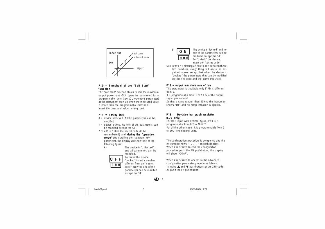
P10 = Threshold of the “Soft Start”P10 = Threshold of the “Soft Start”P10 = Threshold of the “Soft Start”P10 = Threshold of the “Soft Start”P10 = Threshold of the “Soft Start”func t ion .func t ion .func t ion .func t ion .func t ion .The “Soft start” function allows to limit the maximumoutput power (see OLH operative parameter) for aprogrammable time (see tOL operative parameter)at the instrument start up when the measured valueis lower then the programmable threshold.Insert the threshold value, in eng. unit.
P11 = Safety lockP11 = Safety lockP11 = Safety lockP11 = Safety lockP11 = Safety lock0 = device unlocked. All the parameters can be
modified1 = device locked. No one of the parameters can
be modified except the SP.2 to 499 = Select the secret code (to be
remembered) and during the “operativeduring the “operativeduring the “operativeduring the “operativeduring the “operativemode” mode” mode” mode” mode” and scrolling the “software key”parameter, the display will show one of thefollowing figures:A) The device is “Unlocked”
and all parameters can bemodified.To make the device“Locked” insert a numberdifferent from the “secretcode”. Now no one of theparameters can be modifiedexcept the SP.
B) The device is “locked” and noone of the parameters can bemodified except the SP.To “Unlock” the device,insert the “secret code”.
500 to 999 = Selecting a secret code between thesetwo numbers, every thing will occur as ex-plained above except that when the device is“Locked” the parameters that can be modifiedare the set point and the alarm threshold.
P12 = output maximum rate of riseP12 = output maximum rate of riseP12 = output maximum rate of riseP12 = output maximum rate of riseP12 = output maximum rate of riseThis parameter is available only if Pb is differentfrom 0.It is programmable from 1 to 10 % of the outputsignal per second.Setting a value greater then 10%/s the instrumentshows “InF” and no ramp limitation is applied.
P13 = Deviation bar graph resolutionP13 = Deviation bar graph resolutionP13 = Deviation bar graph resolutionP13 = Deviation bar graph resolutionP13 = Deviation bar graph resolution(LDS only)(LDS only)(LDS only)(LDS only)(LDS only)For RTD input with decimal figure, P13 is isprogrammable from 0.2 to 20.0 °C.For all the other inputs, it is programmable from 2to 200 engineering units.
The configuration procedure is completed and theinstrument shows " -.-.-.-. " on both displays.When it is desired to end the configurationprocedure push the FN pushbutton; the displaywill show "COnF".
When it is desired to access to the advancedconfiguration parameter procede as follows:1) using and pushbutton set the 219 code.2) push the FN pushbutton.
Readout
P9
Real curve
adjusted curve
Input
O F FO F FO F FO F FO F Fn n nn n nn n nn n nn n n
O NO NO NO NO N
n n nn n nn n nn n nn n n
lxs-1-0f.pmd 16/01/2004, 9.298

9GBGBGBGBGB
P14 -Display of the protect parameterP14 -Display of the protect parameterP14 -Display of the protect parameterP14 -Display of the protect parameterP14 -Display of the protect parameterenabling/disabling.enabling/disabling.enabling/disabling.enabling/disabling.enabling/disabling.This parameter is available only if P11 is differentfrom 0.This parameter allows to enable/disable thedisplay of the protected parameter during"operative mode".OFF = protected parameter cannot be displayedON = protected parameter can be displayed
P15 - SMART function enabling/ disablingP15 - SMART function enabling/ disablingP15 - SMART function enabling/ disablingP15 - SMART function enabling/ disablingP15 - SMART function enabling/ disabling0 = The SMART function is disabled1 = The SMART function enabling/disabling is
NOT protected by the safety key.2 = The SMART function enabling/disabling is
protected by the safety key.
P16 - Maximum value of the proportional bandP16 - Maximum value of the proportional bandP16 - Maximum value of the proportional bandP16 - Maximum value of the proportional bandP16 - Maximum value of the proportional bandsettable by the SMART functionsettable by the SMART functionsettable by the SMART functionsettable by the SMART functionsettable by the SMART functionThis parameter may be programmed from P17orP18 value to 99.9.
P17 - Minimum value of the proportionalP17 - Minimum value of the proportionalP17 - Minimum value of the proportionalP17 - Minimum value of the proportionalP17 - Minimum value of the proportionalband settable by the SMART function inband settable by the SMART function inband settable by the SMART function inband settable by the SMART function inband settable by the SMART function inheating control only.heating control only.heating control only.heating control only.heating control only.This parameter is present only if P5 is different from5.It may be programmed from 1.0% to P16 value.
P18 - Minimum value of the proportional bandP18 - Minimum value of the proportional bandP18 - Minimum value of the proportional bandP18 - Minimum value of the proportional bandP18 - Minimum value of the proportional bandsettable by the SMART function in heating/settable by the SMART function in heating/settable by the SMART function in heating/settable by the SMART function in heating/settable by the SMART function in heating/cooling control only (LHS)cooling control only (LHS)cooling control only (LHS)cooling control only (LHS)cooling control only (LHS)This parameter is present only when P5 is equal to5.This parameter may be programmed from 1.5% toP17 value.
P19 - Automatic modif ication of "relativeP19 - Automatic modif ication of "relativeP19 - Automatic modif ication of "relativeP19 - Automatic modif ication of "relativeP19 - Automatic modif ication of "relativecooling gain" cooling gain" cooling gain" cooling gain" cooling gain" (LHS)This parameter is present only when P5 is equalto 5.OFF = the SMART function do not not not not not modify the
"relative cooling gain" parameter.ON = the SMART function modify the "relative
cooling gain" parameter.
P20 - Minimum value of integral time settableP20 - Minimum value of integral time settableP20 - Minimum value of integral time settableP20 - Minimum value of integral time settableP20 - Minimum value of integral time settableby SMART function.by SMART function.by SMART function.by SMART function.by SMART function.P20 is programmable from 00.1 (10 seconds) to02.0 (2 minutes).
P21 = Extension of the anti-reset-wind upP21 = Extension of the anti-reset-wind upP21 = Extension of the anti-reset-wind upP21 = Extension of the anti-reset-wind upP21 = Extension of the anti-reset-wind upRange: from -30 to +30 % of the proportionalband.NOTENOTENOTENOTENOTE: a positive value encreases the high limit ofthe anti-reset-wind up (over set point) while anegative value decreases the low limit of the anti-reset-wind up (under set point).
The advanced configuration procedure iscompleted and the instrument shows " CnF" on thedisplay.
lxs-1-0f.pmd 16/01/2004, 9.299

10GBGBGBGBGB
OPERATIVE MODEOPERATIVE MODEOPERATIVE MODEOPERATIVE MODEOPERATIVE MODE
PRELIMINARYPRELIMINARYPRELIMINARYPRELIMINARYPRELIMINARYTo make the instrument operative as controller theinternal switch V2 located on the input card (seeFig. 9) must be closed.
It is assumed, at this point, that the instrument hasbeen correctly configured as detailed in Section 3.
- Models LMS and LHS show on the upperdisplay the measured value and on the lowerdisplay the programmed set point value (wedefine this display condition as “normal displaymode”).
- Model LDS shows the measured value or theset point value (in this case the SP LED will beflashing). In order to revert the indication pushthe pushbutton. (We define this displaycondition as “normal display mode”).
Pressing the FN pushbutton it is possible toscroll all the parameters.- Models LMS and LHS show on the lower
display the abbreviated names and on theupper display the parameters value.
- Model LDS will alternate its reading betweenthe parameter code and its value and, duringmodification, it will show only the parametervalue.
To modify a parameter, first select the desiredparameter by the FN pushbutton, then set thenew value by or pushbuttons. Press FNpushbutton to memorize the new value and stepto the next parameter.NOTENOTENOTENOTENOTE: 1) If, during parameter modification, no
pushbutton is pressed for more than 10seconds, the instrument reverts
automatically to the “normal displaymode” and the new setting of the lastparameter will be lost.
2) The instrument doesn't displays allthe parameters.It select the parameters in accord-ance with:
a) The instrument configuration ingeneral (see chapter 3),
b) The P14 parameter in particular (seechapter 3),
c) The set of the proportional band (seepage 4.2).
INDICATORSINDICATORSINDICATORSINDICATORSINDICATORSST Flashing when the first part of the SMART
algorithm is active.Lit when the second part of the SMARTalgorithm is active.
OUT Lit when the OUT 1 is in ON condition.ALM/COOL - Lit when the alarm 1 is in the alarm
state or, for LDS only, when this output isused as time proportioning control outputand it is in ON condition.
SP (LDS only) Flashing when the displayshows the operative set point.
lxs-1-0f.pmd 16/01/2004, 9.2910

11GBGBGBGBGB
Pushbuttons function:Pushbuttons function:Pushbuttons function:Pushbuttons function:Pushbuttons function:FN = It allows to memorize the new value of
the selected parameter and go to thenext parameter (increasing order).
ST = It allows to enable or disable theSMART function and to scroll back allthe parameters without storing them.
= It allows to increase the value of theselected parameter or (LDS only) todisplay the set point value or themeasured value.
= It allows to decrease the value of theselected parameter.
+ FN = allows to enable/disable the "LAMPTEST"
NOTENOTENOTENOTENOTE: a 10 seconds time out become opera-tional during parameter modification.If, during operative parameter modification, nopushbutton is pressed during this time out, theinstrument reverts automatically to the “normaldisplay mode”. The new setting of the lastparameter modified is going to be memorizzed,prior to the time out, only if the FN pushbuttonwas depressed.
MANUAL RESET OF THE ALARMSMANUAL RESET OF THE ALARMSMANUAL RESET OF THE ALARMSMANUAL RESET OF THE ALARMSMANUAL RESET OF THE ALARMSIf the alarm has been configured as a latchedalarm, the alarm status persists also after thealarm condition disappears.When it is desired to reset the alarm, pushing FNpushbutton select the "n.rS" parameter (thedisplay will show "n.rS" and "OFF"). By the and
pushbuttons select "ON" and push the FNpushbutton again.The alarm reset action will be successful if thealarm condition has disappeared only.
SMART ALGORITHMSMART ALGORITHMSMART ALGORITHMSMART ALGORITHMSMART ALGORITHMIt is used to obtain automatically the best controlaction.To enable the SMART function, push the STpushbutton for more than 1,5 s, when theinstrument is in normal display mode. The STLED will lit continuously or flashing according tothe algorithm automatically selected.When the smart function is enabled, it is possibleto display but not to modify the control param-eters (PB, TI, TD and rC).When the traditional control (PID) is desired, pushthe ST pushbutton again (for more than 1.5 s) toturn the "SMART" OFF. The instrument maintainsthe actual set of control parameters and allowsparameter modification.NOTESNOTESNOTESNOTESNOTES:1) During the SMART function operation, the
relative cooling gain (if present and controlledby SMART) is limited within the followingranges:
Cooling element rangeAir 0.85 to 1.00OIL 0.80 to 0.90H2O 0.30 to 0.60
2) The SMART function use a derivative time equalto 1/4 of the integral time.
3) The limits of the proportional band settable bythe SMART function is programmed by P16,P17 and P18 parameters.
4) The lower limit of the integral time settable bySMART function is programmed by P20parameter.
5) When ON/OFF control is programmed (PB=0),the SMART function is disabled.
6) The SMART enabling/disabling can beprotected by the safety lock (see P15parameter).
lxs-1-0f.pmd 16/01/2004, 9.2911

12GBGBGBGBGB
the instrument will automatically enabled againthis function.
DIRECT ACCESS TO THE SET POINTDIRECT ACCESS TO THE SET POINTDIRECT ACCESS TO THE SET POINTDIRECT ACCESS TO THE SET POINTDIRECT ACCESS TO THE SET POINTMODIFICATIONMODIFICATIONMODIFICATIONMODIFICATIONMODIFICATIONThe instrument allows to modified the set pointvalue without to use the FN pushbutton.When a direct access to set point modification isrequired, proceed as follow:1) Push, for more than 3 seconds, the or
pushbutton; the set point value, will bedisplayed and it will start to change.
2) Using the and pushbuttons, it ispossible to set the desired value.
3) When the desired value is reached, do notpush any pushbutton for more than 3 second,the new set point will become operative after3 second from the last pushbutton pressure.
If, during this procedure, there is no interest inmemorizing the new value, push the FNpushbutton; the instrument returns automaticallyto the normal display mode without havingmemorized the new set point.
DISPLAY OF THE SET POINT VALUEDISPLAY OF THE SET POINT VALUEDISPLAY OF THE SET POINT VALUEDISPLAY OF THE SET POINT VALUEDISPLAY OF THE SET POINT VALUE(LDS only)(LDS only)(LDS only)(LDS only)(LDS only)To display the programmed set point value pushthe pushbutton.The display will show the set point value and thedecimal point of the last significant digit will flashto indicate that the number shown is the set pointvalue.To come back to display the measured value,push the pushbutton again.
OUTPUT POWER OFFOUTPUT POWER OFFOUTPUT POWER OFFOUTPUT POWER OFFOUTPUT POWER OFFThese products allow to turn OFF, manually, theoutput signal in order to stop the control.To turn OFF the output signal, push continuouslythe pushbutton first and then push FNpushbutton.Maintaining pressure on both of them for morethan 3 seconds, the instrument will show "OFF"instead of the set point value.For LDS model, since it has only one display, it ispossible to toggle from "OFF" to measured valueby depressing the pushbutton (the LEDs of thebargraph will be flashing to show that theinstrument is working as an indicator only).In the output power off condition the alarms are in noalarm condition (the alarm output status depends bythe type of alarm action programmed) and theparameters can be re-viewed and modified.When it is desired to come back to the normalcontrol, push continuously the pushbutton firstand then push the FN pushbuttons.Maintaining the pressures on both of them formore than 3 seconds, the instrument returns inNORMAL DISPLAY MODE.NOTES NOTES NOTES NOTES NOTES :1) If the output is turned OFF when the SMART
function was performing the first part of thealgorithm (LED ST is flashing), the SMARTfunction will be aborted and when theinstrument comes back to the normal control,the SMART function will be disabled.If the output is turned OFF when the SMARTfunction was performing the second part of thealgorithm (LED ST is lighting), the SMARTfunction will be stopped and, when theinstrument comes back to the normal control,the smart function also will be activated.
2) If the instrument is turned OFF with the outputpower off function enabled, at the next start up
lxs-1-0f.pmd 16/01/2004, 9.2912

13GBGBGBGBGB
BARGRAPH OPERATINGBARGRAPH OPERATINGBARGRAPH OPERATINGBARGRAPH OPERATINGBARGRAPH OPERATING (LDS only) (LDS only) (LDS only) (LDS only) (LDS only)The 3 LEDs bargraph shows the deviation betweenthe measured value and the set point value.The central LED (green) is lit when the deviation islower than one half of the value programmed withP13 parameter.If the deviation is higher than 1/2 P13 but lowerthan 3/2 P13, one of the red LED will be lit (theright or the left LED according to the deviationdirection).When the deviation is higher than 3/2 P13 therelative LED (left or right) will be flashing.
LAMP TESTLAMP TESTLAMP TESTLAMP TESTLAMP TESTWhen it is desired to verify the display efficiency,push + FN pushbuttons. the instrument willturn ON, with a 50 %duty cicle,all the LED of thedisplay (we define this function "LAMP TEST").No time out is applied to the LAMP TEST.When it is desired to come back to the normaldisplay mode, push + FN pushbuttons again.No other keyboard function are available duringLAMP TEST.
OPERATIVE PARAMETERSOPERATIVE PARAMETERSOPERATIVE PARAMETERSOPERATIVE PARAMETERSOPERATIVE PARAMETERSThe following is a list of all the available controlparameters. Note that some parameters may benot visualized according to the specific instrumentconfiguration.Push the FN pushbutton, the lower display willshow the code while the upper display will showsthe value or the status (ON or OFF) of theselected parameter.By or pushbutton it is possible to set thedesired value or the desired status.Pushing the FN pushbutton, the instrumentmemorizes the new value (or the new status) andgoes to the next parameter.
Param. DESCRIPTIONSP Set point (in eng. units).
Range: from rL to rH.n.rS Manual reset of the alarms.
This parameter is available only whenone alarm with manual reset has beenprogrammed.Set ON and push the FN pusbutton toreset the alarms.
nnn Software key for parameter protection.This parameter is skipped if P11 = 0 or 1ON = the instrument is in LOCKconditionOFF = the instrument is in UNLOCK con-ditionWhen it is desired to switch from LOCKto UNLOCK condition, set a value equalto P11 parameter.When it is desired to switch fromUNLOCK to LOCK condition, set a valuedifferent from P11 parameter.
AL Alarm threshold (in eng. units).This parameters is present if the alarm
lxs-1-0f.pmd 16/01/2004, 9.2913

14GBGBGBGBGB
is configured only.Ranges:- From P2 to P3 for process alarm.- From 0 to 500 units for band alarm.- From -199 to 500 units for deviationalarm.
HSA Alarm hysteresis (in % of P3 - P2 span)This parameters is present if the alarmis configured only.Range:From 0.1% to 10.0% of the inputspan or 1 LSD.NoteNoteNoteNoteNote: If the hysteresis of a band alarm islarger than the alarm band, theinstrument will use an hysteresis valueequal to the alarm band minus 1 digit.
Pb Proportional band (in % of P3 - P2 span)Range::::: from 1.0 % to 99.9 % of span forheating output.From 1.5 % to 99.9 % of span forheating/cooling output (LHS).When PB parameter is set to 0, theinstrument performs an ON-OFF control;the ti, td, C, C2, rC, OLP, OLH and tOLparameters are skipped and SMARTfunction is disabled.
HS Hysteresis for ON/OFF control action (in% of P3 - P2 span)This paameter is available only whenPb=0.Range: from 0.1% to 10.0% of the inputspan.
ti Integral time (in minutes and seconds[mm.ss]). This parameter is skipped ifPb=0 (ON/OFF action).Range: from 00.1 to 20.0 [mm.ss].Above this value the display blanks andintegral action is excluded
td Derivative time (in minutes and seconds[mm.ss]). This parameter is skipped if
Pb=0 (ON/OFF action).Range: from 1 s to 9 min. and 59 s; if 0 isset, the derivative action is excluded.
IP Integral pre-loadThis parameter isskipped when PB = 0.Range:- from 0 to 100% for one control output- from -100 to 100% for two controloutputs (LHS only).
C Output 1 (heating) cycle time (inseconds)This parameter is present if PBparameter is different from 0 only.Range:From 1 to 200 s.
C2 Output 2 (cooling cycle time (LHS only)This parameter is available only if P5=5.Range:From 1 to 200 s.
rC Relative Cooling gain (LHS only).This parameter is present if P5 = 5 andPB parameter is different from 0 only.Range: from 0.20 to 1.00
OLP Dead band/Overlap between H/C outputs(LHS only).This parameter is present if P5 = 5 and PBparameter is different from 0 only.Range: from -20 to 50 % of theproportional band.A negative OLAP value shows a deadband while a positive value shows anoverlap.
rL Set point low limit (in eng. units).Range: from min. range value (P2) to rH.NoteNoteNoteNoteNote: When P2 has been modified, rLwill be realigned to it.
rH Set point high limit (in eng. units).Range:from rL to full scale value (P3).NoteNoteNoteNoteNote: When P3 has been modified, rHwill be realigned to it
lxs-1-0f.pmd 16/01/2004, 9.2914

15GBGBGBGBGB
ERROR MESSAGESERROR MESSAGESERROR MESSAGESERROR MESSAGESERROR MESSAGES
OVERRANGE, UNDERRANGE AND BURN-OVERRANGE, UNDERRANGE AND BURN-OVERRANGE, UNDERRANGE AND BURN-OVERRANGE, UNDERRANGE AND BURN-OVERRANGE, UNDERRANGE AND BURN-OUT INDICATIONSOUT INDICATIONSOUT INDICATIONSOUT INDICATIONSOUT INDICATIONSThe instrument shows the OVERRANGE andUNDERRANGE conditions with the followingindications:
Overrange Underrange
The sensor leads break can be signalled as:- for TC input : OVERRANGE or
UNDERRANGE selected by asolder jumper (see chapter 3)
- for RTD input : OVERRANGE
Sensor leads short circuit detection:On RTD input, a special test is provided to signalOVERRANGE when input resistance is less than15 ohm (Short circuit sensor detection).
NOTENOTENOTENOTENOTE: When:- The instrument is set for one output only and an
OVERRANGE is detected, the OUT 1 turnsOFF (if reverse action) or ON (if direct action).
- The instrument is set for heating/cooling actionand an OVERRANGE is detected, OUT 1 turnsOFF and OUT 2 turns ON.
- The instrument is set for one output only and anUNDERRANGE is detected, the OUT 1 turnsON (if reverse action) or OFF (if direct action).
- The instrument is set for heating/cooling actionand an UNDERRANGE is detected, OUT 1turns ON and OUT 2 turns OFF.
OLH Output high limit (in % of the output).This parameter is present if PBparameter is different from 0 only.Range:- From 0.0 to 100.0 when device isconfigured with one control output.- From -100.0 to 100.0 when device isconfigured with two control outputs (LHSonly).
tOL Time duration of the output powerlimiter.The tOL is a programmable time inwhich the output level is limited to OLHvalue. The count of this time starts atinstrument switching on if the measuredvariable is less than the threshold valueprogrammed (P10 parameter).This parameter is present if PBparameter is different from 0 only.Range: from 1 minute to 100 minutes.Above this limit, the upper display shows"InF" and the limiter will be ever enabledindependently from P10 parametervalue.NoteNoteNoteNoteNote: The tOL can be modified but thenew value will become operative only atthe next instrument start up.
lxs-1-0f.pmd 16/01/2004, 9.2915
16GBGBGBGBGB
NOTE:NOTE:NOTE:NOTE:NOTE: when an overrange or an underrange isdetected, the alarm operate as inpresence of the maximum or theminimum measurable value respectively.
To eliminate the OUT OF RANGE condition,proceed as follows:1) Check the input signal source and the
connecting line.2) Make sure that the input signal is in
accordance with instrument configuration.Otherwise, modify the input configuration (seechapter 3.2).
3) If no error is detected, send back theinstrument to your supplier for a check.
ERRORSERRORSERRORSERRORSERRORSDiagnostics are made at instrument switch-onand during normal mode of operation.If a fault condition (error) is detected, the lowerdisplay will show the message "Er" while theupper display shows the relative error code.For LDS model, the display will show alternatly"Er" and the error number.The following is a list of possible errors innumerical order.Also causes, instrument output conditions andpossible remedies are briefly described.Some errors reset the instrument; if the errorpersist, send back the instrument to your supplier.
ERROR LISTERROR LISTERROR LISTERROR LISTERROR LIST
100 Write EEPROM error.150 General hardware error on the CPU
card.200 Tentative to write on protected
memory.201 - 2xx Configuration parameter error. The
two less significant digit’s shown thenumber of the wrong parameter (ex.209 Err show an Error on P9parameter)
301 RTD calibration error.305 Thermocouple input calibration
error.307 RJ input calibration error400 Control parameters error500 Auto-zero error502 RJ error510 Error during calibration procedure
NOTENOTENOTENOTENOTE1) When a configuration parameter error is
detected, it is sufficient to repeat the configura-tion procedure of the specify parameter.
2) If an error 400 is detected, push contemporar-ily the and pushbuttons for loading thedefault parameters then repeat controlparameter setting.
3) For all the other errors, contact your supplier.
lxs-1-0f.pmd 16/01/2004, 9.2916

17GBGBGBGBGB
GENERAL INFORMATIONGENERAL INFORMATIONGENERAL INFORMATIONGENERAL INFORMATIONGENERAL INFORMATION
GENERAL SPECIFICATIONSGENERAL SPECIFICATIONSGENERAL SPECIFICATIONSGENERAL SPECIFICATIONSGENERAL SPECIFICATIONSCaseCaseCaseCaseCase: ABS grey color (RAL 7043); self-extinguish-
ing degree: V-0 according to UL 94.Front protectionFront protectionFront protectionFront protectionFront protection - designed for IP 65 (*) and NEMA4X (*) for indoor locations (when panel gasket isinstalled).(*) Test were performed in accordance with CEI 70-1and NEMA 250-1991 STD.InstallationInstallationInstallationInstallationInstallation: panel mounting by means of mountingbraket. Instrument removable from case.Rear terminal blockRear terminal blockRear terminal blockRear terminal blockRear terminal block:10 screw terminals ( screwM3, for cables from φ 0.25 to φ 2.5 mm2 or fromAWG 22 to AWG 14 ) with connection diagramsand safety rear cover.DimensionsDimensionsDimensionsDimensionsDimensions: 48 x 48 mm, depth 100 mm (DIN43700).WeightWeightWeightWeightWeight: 160 g max.Power supplyPower supplyPower supplyPower supplyPower supply:- 100V to 240V AC 50/60Hz (-15% to + 10% ofthe nominal value).- 24 V AC/DC (+ 10 % of the nominal value).Power consumptionPower consumptionPower consumptionPower consumptionPower consumption: 6 VA max.Insulation voltagensulation voltagensulation voltagensulation voltagensulation voltage: 2300 V rms according toEN 61010-1.Display updating timeDisplay updating timeDisplay updating timeDisplay updating timeDisplay updating time: 500 ms.Sampling time: Sampling time: Sampling time: Sampling time: Sampling time: 500 ms.ResolutionResolutionResolutionResolutionResolution: 30000 counts.Accuracy Accuracy Accuracy Accuracy Accuracy (@ 25 °C): +0.3% of the input span +1 °C.Common mode rejectionCommon mode rejectionCommon mode rejectionCommon mode rejectionCommon mode rejection: 120 dB at 50/60 Hz.Normal mode rejection:Normal mode rejection:Normal mode rejection:Normal mode rejection:Normal mode rejection: 60 dB at 50/60 Hz.Electromagnetic compatibility and safetyElectromagnetic compatibility and safetyElectromagnetic compatibility and safetyElectromagnetic compatibility and safetyElectromagnetic compatibility and safetyrequirementsrequirementsrequirementsrequirementsrequirements: This instrument is marked CE.Therefore, it is conforming to council directives89/336/EEC and to council directives 73/23/EECand 93/68/EEC.Instal lation categoryInstal lation categoryInstal lation categoryInstal lation categoryInstal lation category: IITemperature driftTemperature driftTemperature driftTemperature driftTemperature drift: < 200 ppm/°C (RJ excluded)
< 400 ppm/°C for RTD input with -19.9/99.9 °C rangeand TC type T.Reference junction driftReference junction driftReference junction driftReference junction driftReference junction drift: 0.1 °C/°C.Operative temperatureOperative temperatureOperative temperatureOperative temperatureOperative temperature: from 0 to 50 °C.Storage temperature : Storage temperature : Storage temperature : Storage temperature : Storage temperature : -20 to +85 °CHumidityHumidityHumidityHumidityHumidity: from 20 % to 85% RH, non condensing.Protect ionsProtect ionsProtect ionsProtect ionsProtect ions:1) WATCH DOG circuit for automatic restart.2) DIP SWITCH for protection against tampering ofconfiguration and calibration parameters.Altitude : Altitude : Altitude : Altitude : Altitude : this product is not suitable for useabove 2000m (6562 ft)
INPUTSINPUTSINPUTSINPUTSINPUTSA) A) A) A) A) THERMOCOUPLETHERMOCOUPLETHERMOCOUPLETHERMOCOUPLETHERMOCOUPLETypeTypeTypeTypeType: L, J, K, N, T programmable by frontpushbuttons.Line resistanceLine resistanceLine resistanceLine resistanceLine resistance: max. 100 Ω with error <+0.1%of the input span.Engineering unitEngineering unitEngineering unitEngineering unitEngineering unit: °C or °F programmable.Reference junctionReference junctionReference junctionReference junctionReference junction: automatic compensationfrom 0 to +50 °C.Reference junction driftReference junction driftReference junction driftReference junction driftReference junction drift : 0.1 °C/°C.Burn-outBurn-outBurn-outBurn-outBurn-out: Up or down scale selectable.CalibrationCalibrationCalibrationCalibrationCalibration: according to IEC 584-1 and DIN43710 - 1977 (TC L)STANDARD RANGES TABLE
TCTCTCTCTC
typetypetypetypetype
LLLLL
JJJJJ
KKKKK
NNNNN
TTTTT
0 - +800 °C
0 - +800 °C
0 - +999 °C
0 - +999 °C
0 - + 400 °C
Measuring rangesMeasuring rangesMeasuring rangesMeasuring rangesMeasuring ranges
0 - +999 °F
0 - +999 °F
0 - +999 °F
0 - +999 °F
0 - +752 °F
lxs-1-0f.pmd 16/01/2004, 9.2917

18GBGBGBGBGB
B) RTDB) RTDB) RTDB) RTDB) RTD (RRRRResistance TTTTTemperature DDDDDetector)TypeTypeTypeTypeType: Pt 100 3 wires connection.CurrentCurrentCurrentCurrentCurrent: 135 µA.Line resistanceLine resistanceLine resistanceLine resistanceLine resistance: automatic compensation up to20 Ω/wire with :- error <+0.1% of the input span for range -19.9 a99.9 °C.- not measurable error for the other ranges.Engineering unitsEngineering unitsEngineering unitsEngineering unitsEngineering units: °C or °F programmable.Burn-outBurn-outBurn-outBurn-outBurn-out: up scale. NOTENOTENOTENOTENOTE: a special test isprovided to signal OVERRANGE when inputresistance is less than 15 Ω.CalibrationCalibrationCalibrationCalibrationCalibration: according to DIN 43760
STANDARD RANGES TABLE
CONTROL ACTIONSCONTROL ACTIONSCONTROL ACTIONSCONTROL ACTIONSCONTROL ACTIONS
Control actionsControl actionsControl actionsControl actionsControl actions: PID + SMARTProportional bandProportional bandProportional bandProportional bandProportional band: from 1.0 % (for heatingaction) or 1.5 % (for heating and cooling action)to 99.9 % of the input span.Setting Pb = 0 an ON/OFF control is performed.Hysteresis Hysteresis Hysteresis Hysteresis Hysteresis (for ON/OFF control action): from 0.1% to 10.0 % of the input span.Integral timeIntegral timeIntegral timeIntegral timeIntegral time: from 10 seconds to 20 minutes;resolution 10 second. Setting a value upper than20 minutes the integral action will be excluded.Derivative timeDerivative timeDerivative timeDerivative timeDerivative time: from 0 to 9 minutes and 59seconds.
Integral preload:Integral preload:Integral preload:Integral preload:Integral preload:- from 0 to 100% for one control output.- from -100 to 100% for two control outputs (LHS only).Heating cycle timeHeating cycle timeHeating cycle timeHeating cycle timeHeating cycle time: from 1 to 200 s.Cooling cycle timeCooling cycle timeCooling cycle timeCooling cycle timeCooling cycle time: from 1 to 200 s (LHS only).Relative cooling gainRelative cooling gainRelative cooling gainRelative cooling gainRelative cooling gain: from 0.20 to 1.00 (LHSonly).NOTENOTENOTENOTENOTE: the PB, TI, TD and RCG parameter maybe limited when the SMART function is enabled.Overlapping/dead bandOverlapping/dead bandOverlapping/dead bandOverlapping/dead bandOverlapping/dead band: from - 20 % to 50 %(LHS only)
CONTROL OUTPUTSCONTROL OUTPUTSCONTROL OUTPUTSCONTROL OUTPUTSCONTROL OUTPUTS
OUTPUT 1 - heatingOUTPUT 1 - heatingOUTPUT 1 - heatingOUTPUT 1 - heatingOUTPUT 1 - heating:a ) Relay output with SPDT contact;
contact rating 3A / 250 V ac on resistive load.b) Logic voltage for SSR drive.
Logic status 1: 24 V +20% @ 1 mA.14 V +20% @ 20 mA
Logic status 0: <0.5 VOutput actionOutput actionOutput actionOutput actionOutput action: direct/reverse programmable (notavailable for LHS used for heating/coolingcontrol).
OUTPUT 2 - cooling OUTPUT 2 - cooling OUTPUT 2 - cooling OUTPUT 2 - cooling OUTPUT 2 - cooling (LHS only) / alarm 1/ alarm 1/ alarm 1/ alarm 1/ alarm 1a ) Relay output with SPST contact;
contact rating 1A / 250 V ac on resistive load.By internal jumper it is possible to select theNC or NO contact.
RTDRTDRTDRTDRTD
TYPETYPETYPETYPETYPE
RTD Pt 100
RTD Pt 100
-199 - +500 °C
-19.9 - +99.9 °C
Measuring rangeMeasuring rangeMeasuring rangeMeasuring rangeMeasuring range
-199 - +999 °F
-----
lxs-1-0f.pmd 16/01/2004, 9.2918
19GBGBGBGBGB
MAINTENANCEMAINTENANCEMAINTENANCEMAINTENANCEMAINTENANCE1) REMOVE POWER FROM THE POWER SUPPLY
TERMINALS AND FROM RELAY OUTPUTTERMINALS
2) Remove the instrument from case.3) Using a vacuum cleaner or a compressed air jet
(max. 3 kg/cm2) remove all deposit of dust anddirt which may be present on the louvers and onthe internal circuits trying to be careful for notdamage the electronic components.
4) To clean external plastic or rubber parts useonly a cloth moistened with:- Ethyl Alcohol (pure or denatured) [C2H5OH] or- Isopropil Alcohol (pure or denatured)[(CH3)2CHOH] or- Water (H2O)
5) Verify that there are no loose terminals.6) Before re-inserting the instrument in its case,
be sure that it is perfectly dry.7) re-insert the instrument and turn it ON.
lxs-1-0f.pmd 16/01/2004, 9.2919

1FFFFF
MONTAGEMONTAGEMONTAGEMONTAGEMONTAGE
Choisir une position propre pour le montage,d'accès facile même à l'arrière et, autant quepossible, sans vibrations. La températureambiante doit être comprise entre 0 et 50°C.L'instrument peut être monté sur un panneaud'épaisseur maxi. 15 mm après avoir exécuté untrou de 45 x 45 mm.Pour les dimensions d'encombrement et deperçage, se reporter à la page IV.La rugosité superficielle du panneau doit êtremeilleure que 6,3 µm.L'instrument est doté d'un joint en caoutchoucpour panneau (de 50 à 60 Sh).Pour garantir les protections IP65 et NEMA 4,introduire le joint livrée avec l'appareil entrel'instrument et le panneau (voir Figure 1)Pour fixer l'instrument au panneau, agir commesuit:1) enfiler le joint sur le boîtier de l'instrument,2) introduire l'instrument dans le trou,3) en maintenant fermement l'instrument sur lepanneau, introduire la bretelle de fixation4) au moyen d'un tourne-vis, serrer les vis à uncouple compris entre 0,3 et 0,4 Nm
panneau
bretellevis
Joint
Fig. 1
LXS-2-0F.pmd 16/01/2004, 9.251

2FFFFF
A) ENTREES DE MESUREA) ENTREES DE MESUREA) ENTREES DE MESUREA) ENTREES DE MESUREA) ENTREES DE MESURENOTENOTENOTENOTENOTE: Des éléments extérieurs (ex. barrièrezener) raccordés entre le capteur et les bornesd'entrée de l'instrument, peuvent provoquer deserreurs de mesure dues à une impédence tropélevée ou déséquilibrée, ou à la présence decourants de perte.
ENTREE POUR THERMOCOUPLEENTREE POUR THERMOCOUPLEENTREE POUR THERMOCOUPLEENTREE POUR THERMOCOUPLEENTREE POUR THERMOCOUPLE
Fig. 4 RACCORDEMENT DE THERMOCOUPLESNOTESNOTESNOTESNOTESNOTES:1) Ne pas placer de câbles de signaux parallèlement
ou à proximité des câbles de puissance ou dessources de perturbations
2) Pour le raccordement de la TC utiliser un câblede compensation/extension approprié et,autant que possible, blindé.
3) Quand on utilise un câble blindé, une seuleextrémité du blindage doit être raccordée à laterre.
3
2
+
_
3
2
+
_
Blindage
Blindage
RACCORDEMENTS ELECTRIQUESRACCORDEMENTS ELECTRIQUESRACCORDEMENTS ELECTRIQUESRACCORDEMENTS ELECTRIQUESRACCORDEMENTS ELECTRIQUES
Les raccordements électriques ne doivent êtreeffectués que si le boîtier de l'instrument estrégulièrement monté sur le panneau.
Fig. 2 FACE ARRIERE
LXS-2-0F.pmd 16/01/2004, 9.252
3FFFFF
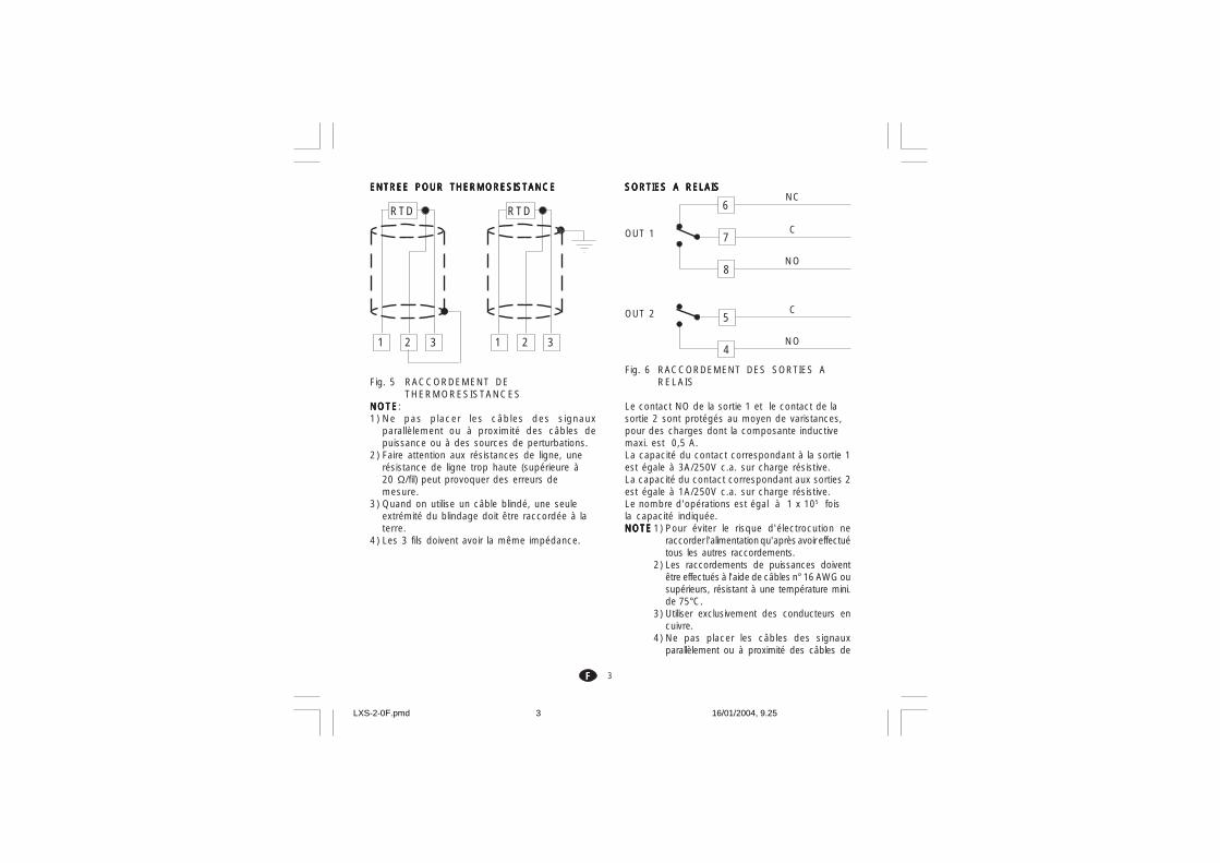
ENTREE POUR THERMORESISTANCEENTREE POUR THERMORESISTANCEENTREE POUR THERMORESISTANCEENTREE POUR THERMORESISTANCEENTREE POUR THERMORESISTANCE
Fig. 5 RACCORDEMENT DETHERMORESISTANCES
NOTENOTENOTENOTENOTE:1) Ne pas placer les câbles des signaux
parallèlement ou à proximité des câbles depuissance ou à des sources de perturbations.
2) Faire attention aux résistances de ligne, unerésistance de ligne trop haute (supérieure à20 Ω/fil) peut provoquer des erreurs demesure.
3) Quand on utilise un câble blindé, une seuleextrémité du blindage doit être raccordée à laterre.
4) Les 3 fils doivent avoir la même impédance.
1
RTD
32 1
RTD
32
SORTIES A RELAISSORTIES A RELAISSORTIES A RELAISSORTIES A RELAISSORTIES A RELAIS
Fig. 6 RACCORDEMENT DES SORTIES ARELAIS
Le contact NO de la sortie 1 et le contact de lasortie 2 sont protégés au moyen de varistances,pour des charges dont la composante inductivemaxi. est 0,5 A.La capacité du contact correspondant à la sortie 1est égale à 3A/250V c.a. sur charge résistive.La capacité du contact correspondant aux sorties 2est égale à 1A/250V c.a. sur charge résistive.Le nombre d'opérations est égal à 1 x 10⁵ foisla capacité indiquée.NOTENOTENOTENOTENOTE 1) Pour éviter le risque d'électrocution ne
raccorder l'alimentation qu'après avoir effectuétous les autres raccordements.
2) Les raccordements de puissances doiventêtre effectués à l'aide de câbles n° 16 AWG ousupérieurs, résistant à une température mini.de 75°C.
3) Utiliser exclusivement des conducteurs encuivre.
4) Ne pas placer les câbles des signauxparallèlement ou à proximité des câbles de
8
6
7C
NC
NO
OUT 1
4
5C
NO
OUT 2
LXS-2-0F.pmd 16/01/2004, 9.253

4FFFFF
+
_ _+
8
7
OUT 1
RELAISSTATIQUE
CHARGE(mA)
<40 mA<150 mA<0.5 A
C(mF)
0.0470.10.33
R(W)
1002247
P.(W)
1/222
Tension deservice
260 V AC260 V AC260 V AC
puissance ou à des sources de perturbations.Les recomandations suivantes peuvent éviter desérieux problèmes causés par l'utilisation dessorties à relais pour piloter les charges inductives.
CHARGES INDUCTIVESCHARGES INDUCTIVESCHARGES INDUCTIVESCHARGES INDUCTIVESCHARGES INDUCTIVES
Dans la commutation des charges inductives, certainescharges inductives peuvent provoquer des transitoires etdes perturbations qui peuvent compromettre lesprestations de l'instrument.Les protections internes (varistances) garantissent laprotection contre les perturbations pour des chargesayant une composante inductive maxi. de 0,5 A.Des problèmes analogues peuvent être créés par lacommutation des charges via un contact extérieurmonté en série sur le contact de sortie de l'instrumentou par l'utilisation du contact NC de la sortie 1.
Fig. 7 CONTACT EXTERIEUR MONTE EN SERIESUR LE CONTACT DE SORTIE DE L'INSTRUMENT
En de tels cas, nous recommandons de raccorderun filtre RC en parallèle avec le contact extérieur,suivant les indications fig. 7Les valeurs de la capacité (C) et de la résistance(R) sont indiquées au tableau suivant:
De toute façon, les câbles raccordés aux sorties àrelais, doivent être aussi éloignés plus que possibledes câbles des signaux.
SORTIE LOGIQUE POUR LA COMMANDE DESORTIE LOGIQUE POUR LA COMMANDE DESORTIE LOGIQUE POUR LA COMMANDE DESORTIE LOGIQUE POUR LA COMMANDE DESORTIE LOGIQUE POUR LA COMMANDE DESSRSSRSSRSSRSSR
Fig. 8 RACCORDEMENT POUR LEPILOTAGE DE RELAIS STATIQUES
Il s'agit d'une sortie à temps proportionnel.Niveau logique 0Niveau logique 0Niveau logique 0Niveau logique 0Niveau logique 0: Vout < 0.5 V c.c.Niveau logique 1Niveau logique 1Niveau logique 1Niveau logique 1Niveau logique 1: Courant maxi. = 20 mA.- 14 V + 20 % @ 20 mA- 24 V + 20 % @ 1 mA.NOTENOTENOTENOTENOTE: Cette sortie N'EST PAS isolée.Un isolement double ou renforcè entre l'instrumentet la ligne de puissance doit être effectué par lerelais statique extérieur.
C) ALIMENTATIONC) ALIMENTATIONC) ALIMENTATIONC) ALIMENTATIONC) ALIMENTATION
Fig. 3 RACCORDEMENT A L'ALIMENTATION
9
R (
S,T
)R (S,T)
N
10N
Réseau de 100 V à 240 V c.a (50/60Hz)
ou 24 V c.c./c.a
C R
LOAD
POWERLINE
LXS-2-0F.pmd 16/01/2004, 9.254

5FFFFF
NOTENOTENOTENOTENOTE:1) Avant de raccorder l'instrument au réseau,
vérifier que la tension de ligne correspond auxindications de la plaque signalétique del'instrument.
2) Pour éviter le risque d'électrocution ne raccorderl'alimentation qu'après avoir effectué tous lesautres raccordements.
3) Le raccordement au réseau doit être effectué àl'aide de câbles n° 16 AWG ou supérieurs,résistant à une température mini. de 75°C.
4) Utiliser exclusivement des conducteurs en cuivre.5) Eviter de placer les câbles des signaux
parallèlement ou à proximité des câbles depuissance ou des sources de perturbations.
6) En cas d'alimentation 24 V c.c./c.a. la polarité n'aaucune importance.
7) Les circuits d'alimentation NE sont PASprotégés par un fusible, nous conseillons d'enprévoir un à l'extérieur ayant lescaractéristiques suivantes:Fusible type T, 1 A, 250V.
8) Les normes sur la sécurité concernant lesinstruments raccordés en permanence àl'alimentation électrique exigent:- un interrupteur ou un disjoncteur sur
l'installation électrique de l'immeuble;- cet interrupteur doit se trouver à proximité de
l'instrument et l'opérateur doit pouvoir yaccéder facilement;
- cet interrupteur doit être marqué comme ledispositif de coupure de l'instrument.
NOTENOTENOTENOTENOTE: un seul interrupteur ou disjoncteur peutcommander plusieurs instruments.
MISE AU POINT PRELIMINAIREMISE AU POINT PRELIMINAIREMISE AU POINT PRELIMINAIREMISE AU POINT PRELIMINAIREMISE AU POINT PRELIMINAIREDU MATERIEL INFORMATIQUEDU MATERIEL INFORMATIQUEDU MATERIEL INFORMATIQUEDU MATERIEL INFORMATIQUEDU MATERIEL INFORMATIQUE1) Extraire l'instrument de son boîtier.2) Positionner le contact interne V2 sur la positionouverte.
3) Ces instruments permettentde relever l'ouverture ducircuit d'entrée(TC ou RTD)visualisé comme une conditionde dépassement d'échellepositif. Uniquement pour lesthermocouples ou peutsélectionner, au moyen descontacts SH401 et CH401indiqués sur la fig. ci-contre, letype d'indication que l'ondésire obtenir en cas dethercouple ouvert.
SH401 CH401 Indication
ouvert fermé Dép. éch. pos.(Std)
fermé ouvert Dép. échelle nég.
Fig. 9
V2
SH401CH401
LXS-2-0F.pmd 16/01/2004, 9.255

6FFFFF
PROCEDURE DE CONFIGURATIONPROCEDURE DE CONFIGURATIONPROCEDURE DE CONFIGURATIONPROCEDURE DE CONFIGURATIONPROCEDURE DE CONFIGURATION
P1 - Type d'entrée et échelle standardP1 - Type d'entrée et échelle standardP1 - Type d'entrée et échelle standardP1 - Type d'entrée et échelle standardP1 - Type d'entrée et échelle standard0 = TC type L échelle 0 / +800 °C1 = TC type J échelle 0 / +800 °C2 = TC type K échelle 0 / +999 °C3 = TC type N échelle 0 / +999 °C4 = RTD type Pt 100 échelle -199 / +500 °C5 = RTD type Pt 100 échelle -19.9 / +99.9 °C6 = TC type T échelle 0 / +400 °C8 = TC type L échelle 0 / +999 °F9 = TC type J échelle 0 / +999 °F10 = TC type K échelle 0 / +999 °F11 = TC type N échelle 0 / +999 °F12 = RTD type Pt 100 échelle -199 / +999 °F13 = TC type T échelle 0 / +752 °FNOTENOTENOTENOTENOTE: Pour les échelles de mesure en °F, ondispose d'une étiquette collante indiquant °F àcoller sur le panneau avant de l'instrument.Cette étiquette, reportée sur "INDEX" de cemanuel, doit être placée sur l'indication °C.
P2 = Echelle mini.P2 = Echelle mini.P2 = Echelle mini.P2 = Echelle mini.P2 = Echelle mini.Non disponible si P1 = 5Valeur d'échelle mini. utilisée par l'algorithme PIDpour les calcul de l'étendue de l'échelled'utilisation.
P3 = Echelle maxi.P3 = Echelle maxi.P3 = Echelle maxi.P3 = Echelle maxi.P3 = Echelle maxi.Non disponible si P1 = 5Valeur d'échelle maxi. utilisée par l'algorithme PIDNOTESNOTESNOTESNOTESNOTES:1) l'étendue de l'échelle d'utilisation programmée
(P3 - P2) doit être supérieure à 300 °C ou 600°F pour l'entrée de thermocouple; 100 °C ou200 °F pour l'entrée de thermorésistance.
2) En modifiant la valeur de P3 et/ou P4, lesparamètres rL et rH seront automatiquementalignés respectivement à la nouvelle valeur deP3 et P4.
4) Si l'instrument a été programmé pour lavisualisation en °F, appliquer l'étiquettesupplémentaire, située sur la page de l'INDEX,sur le panneau avant de l'instrument pourcouvrir l'unité technique (°C)
5) Rebrancher l'instrument.6) Alimenter l'instrument.
L'instrument visualise: “CnF”.ATTENTION: ATTENTION: ATTENTION: ATTENTION: ATTENTION: Si l'instrument visualisel'indication "CAL" appuyer immédiatement sur latouche pour retourner à la phase deconfiguration.
7) Appuyer sur la touche FN.Pour LMS-LHS, l'indicateur inférieur visualise lecode du paramètre sélectionné tandis quel'indicateur supérieur en visualise la nouvellevaleur.Pour LDS le code du paramètre et sa valeurcorrespondante sont visualisés alternativement.
NOTES GENERALES de configuration.NOTES GENERALES de configuration.NOTES GENERALES de configuration.NOTES GENERALES de configuration.NOTES GENERALES de configuration.FN = Permet de mémoriser la nouvelle
valeur du paramètre sélectionné etpasser au paramètre suivant (ordrecroissant).
ST = Permet de visualiser les paramètresen ordre décroissant, sans mémoriserles nouvelles valeurs.
= Permet d'augmenter la valeur duparamètre sélectionné.
= Permet de diminuer la valeur duparamètre sélectionné.
°F°F°F°F°F
LXS-2-0F.pmd 16/01/2004, 9.256
7FFFFF
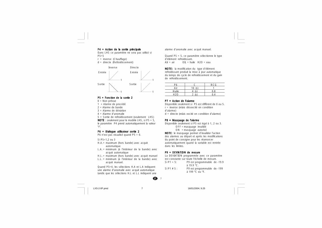
P4 = Action de la sortie principaleP4 = Action de la sortie principaleP4 = Action de la sortie principaleP4 = Action de la sortie principaleP4 = Action de la sortie principaleDans LHS ce paramètre ne sera pas utilisé siP5=5r = inverse (Chauffage)d = directe (Refroidissement)
P5 = Fonction de la sortie 2P5 = Fonction de la sortie 2P5 = Fonction de la sortie 2P5 = Fonction de la sortie 2P5 = Fonction de la sortie 20 = Non prévue1 = Alarme de procédé2 = Alarme de bande3 = Alarme de déviation4 = Alarme d'anomalie5 = Sortie de refroidissement (seulement LHS)NOTE NOTE NOTE NOTE NOTE : seulement pour le modèle LHS, si P5 = 5,le paramètre P4 prend automatiquement la valeur“r”.
P6 = Dialogue utilisateur sortie 2P6 = Dialogue utilisateur sortie 2P6 = Dialogue utilisateur sortie 2P6 = Dialogue utilisateur sortie 2P6 = Dialogue utilisateur sortie 2P6 n'est pas visualisé quand P5 = 0.
Si P5=1,2 ou 3H.A.= maximum (hors bande) avec acquit
automatiqueL.A. = minimum (à l'intérieur de la bande) avec
acquit automatiqueH.L. = maximum (hors bande) avec acquit manuelL.L. = minimum (à l'intérieur de la bande) avec
acquit manuel.
Quand P5=4, les sélections H.A et L.A indiquentune alarme d'anomalie avec acquit automatiquetandis que les sélections H.L et L.L indiquent une
t
Entrée
t
Sortie
t
Entrée
t
Sortie
Inverse Directe
alarme d'anomalie avec acquit manuel.
Quand P5 = 5, ce paramètre sélectionne le typed'élément refroidissant.AIr = air OIL = huile H2O = eau
NOTE:NOTE:NOTE:NOTE:NOTE: la modification du type d'élémentrefroidissant produit la mise à jour automatiquedu temps de cycle de refroidissement et du gainde refroidissement.
P6 C RCGAir 10 (s) 1
Huile 4 (s) 0.8H2O 2 (s) 0.4
P7 = Action de l'alarmeP7 = Action de l'alarmeP7 = Action de l'alarmeP7 = Action de l'alarmeP7 = Action de l'alarmeDisponible seulement si P5 est différent de 0 ou 5.r = inverse (relais désexcité en conditiond'alarme)d = directe (relais excité en condition d'alarme)
P8 = Masquage de l'alarmeP8 = Masquage de l'alarmeP8 = Masquage de l'alarmeP8 = Masquage de l'alarmeP8 = Masquage de l'alarmeDisponible seulement si P5 est égal à 1, 2 ou 3.
OFF = masquage invalidéON = masquage autorisé
NOTENOTENOTENOTENOTE: le masquage permet d'invalider l'actiondes alarmes au départ et après les modificationsdu point de consigne pour les réamorcerautomatiquement quand la variable est rentréedans les limites.
P9 = DEVIATION de mesureP9 = DEVIATION de mesureP9 = DEVIATION de mesureP9 = DEVIATION de mesureP9 = DEVIATION de mesureLa DEVIATION programmée avec ce paramètreest constante sur toute l'échelle de mesure.Si P1 = 5: P9 est programmable de -19.9
à 19.9 °C.Si P1 # 5 : P9 est programmable de -199
à 199 °C ou °F.
LXS-2-0F.pmd 16/01/2004, 9.257

8FFFFF
P10 = Seuil “Soft Start”P10 = Seuil “Soft Start”P10 = Seuil “Soft Start”P10 = Seuil “Soft Start”P10 = Seuil “Soft Start”La fonction “Soft Start” permet de limiter lapuissance de sortie (voir le paramètre defonctionnement OLH) pendant une durée de tempsprogrammable (voir le paramètre defonctionnement tOL) à la mise en service del'instrument si la valeur mesurée est inférieure àun seuil fixé d'avance.P10 est la valeur de seuil, en unités techniques,pour l'activation de la fonction "Soft Start".
P11 = Clé d'accès aux paramètres de contrôleP11 = Clé d'accès aux paramètres de contrôleP11 = Clé d'accès aux paramètres de contrôleP11 = Clé d'accès aux paramètres de contrôleP11 = Clé d'accès aux paramètres de contrôle0 = clé invalidée. Tous les paramètres peuvent
être modifiés1 = clé autorisée. Aucun paramètre ne peut être
modifié, sauf le point de consigne.De 2 à 499 = SP peut toujours être modifié;
Sélectionner le code secret (ne pas l'oublier)qui permet, pendant le dialogue utilisateur,d'autoriser/invalider la clé d'accès. Pendantle dialogue utilisateur, l'instrument visualisel'une des indications suivantes:A ) La clé est invalidée et tous
les paramètres peuventêtre modifiés.Pour autoriser la clé etprotéger les paramètres, ilsuffit d'entrer un numérodifférent du "code secret".
B) La clé est autorisée etaucun paramètre ne peutêtre modifié sauf SP.Pour invalider la clé etpermettre la modificationdes paramètres, il suffitd'entrer le "code secret".
De 500 à 999 En sélectionnant un code secretcompris entre 500 et 999, l'instrument suit lesindications précédentes mais, si la clé estautorisée, l'instrument permet la modificationdu point de consigne et du seuil d'alarme.
P12 =P12 =P12 =P12 =P12 = Vitesse maxi. de variation duVitesse maxi. de variation duVitesse maxi. de variation duVitesse maxi. de variation duVitesse maxi. de variation dusignal de sortiesignal de sortiesignal de sortiesignal de sortiesignal de sortie
Ce paramètre est disponible si Pb est différentde 0.Programmable de 1 à 10 % du signal de sortiepar seconde.Au-delà de 10 %/s l'instrument visualise “InF”pour indiquer l'exclusion de la limite.
P13P13P13P13P13===== Risolution du bar graph de déviationRisolution du bar graph de déviationRisolution du bar graph de déviationRisolution du bar graph de déviationRisolution du bar graph de déviation(seulement LDS).(seulement LDS).(seulement LDS).(seulement LDS).(seulement LDS).
Pour l'entrée RTD avec un chiffre décimal, P13est programmable de 0,2 à 20,0 °CPour toutes les autres entrées, P13 estprogrammable de 2 à 200 unités techniques.
La configuration est complète et l'instrumentvisualise “ -.-.-. “ sur les deux indicateurs.Pour accéder aux paramètres de configurationsecondaires, agir comme suit:1) En utilisant les touches et programmer le
code 219.2) Appuyer sur la touche FN.Pour achever la procédure de configurationappuyer sur la touche FN; l'indicateur visualise"CnF".
Courbemodifiée
Entrée
P9
Visuali. Courberéelle
O F FO F FO F FO F FO F Fn n nn n nn n nn n nn n n
O NO NO NO NO N
n n nn n nn n nn n nn n n
LXS-2-0F.pmd 16/01/2004, 9.258

9FFFFF
P14 -P14 -P14 -P14 -P14 - Autorisation/inval idation de laAutorisation/inval idation de laAutorisation/inval idation de laAutorisation/inval idation de laAutorisation/inval idation de lavisualisation des paramètres protégésvisualisation des paramètres protégésvisualisation des paramètres protégésvisualisation des paramètres protégésvisualisation des paramètres protégés
Ce paramètre est disponible si P 11 est différentde 0.Ce paramètre permet d'autoriser ou d'invalider,pendant le dialogue utilisateur, la visualisationdes paramètres protégés.OFF = Les paramètres protégés ne peuvent pasêtre visualisésON = Les paramètres protégés peuvent êtrevisualisés
P15 - Autorisation/invalidation de la fonctionP15 - Autorisation/invalidation de la fonctionP15 - Autorisation/invalidation de la fonctionP15 - Autorisation/invalidation de la fonctionP15 - Autorisation/invalidation de la fonctionSMARTSMARTSMARTSMARTSMART
0 = La fonction SMART estinvalidée
1 = L'autorisation/invalidation de lafonction SMART N'EST PASprotégée par le code desécurité
2 = L'autorisation/invalidation de lafonction SMART est protégéepar le code de sécurité.
P16 -P16 -P16 -P16 -P16 - Valeur maxi. de bande proportionnelleValeur maxi. de bande proportionnelleValeur maxi. de bande proportionnelleValeur maxi. de bande proportionnelleValeur maxi. de bande proportionnelleprogrammable automatiquement par laprogrammable automatiquement par laprogrammable automatiquement par laprogrammable automatiquement par laprogrammable automatiquement par lafonction SMART.fonction SMART.fonction SMART.fonction SMART.fonction SMART.
Ce paramètre peut prendre les valeurs comprisesentre P17, ou P18 et 99.9.
P17 -P17 -P17 -P17 -P17 - Valeur mini. de bande proportionnelle Valeur mini. de bande proportionnelle Valeur mini. de bande proportionnelle Valeur mini. de bande proportionnelle Valeur mini. de bande proportionnelleprogrammable automatiquement par laprogrammable automatiquement par laprogrammable automatiquement par laprogrammable automatiquement par laprogrammable automatiquement par lafonction SMART pour les instrumentsfonction SMART pour les instrumentsfonction SMART pour les instrumentsfonction SMART pour les instrumentsfonction SMART pour les instrumentsavec une seule sortie de régulation.avec une seule sortie de régulation.avec une seule sortie de régulation.avec une seule sortie de régulation.avec une seule sortie de régulation.
Ce paramètre est visualisé uniquement si P5 estdifférent de 5.P17 peut prendre les valeurs comprises entre1,0% et la valeur de P16.
P18 -P18 -P18 -P18 -P18 - Valeur mini. de bande proportionnelle Valeur mini. de bande proportionnelle Valeur mini. de bande proportionnelle Valeur mini. de bande proportionnelle Valeur mini. de bande proportionnelleprogrammable automatiquement par laprogrammable automatiquement par laprogrammable automatiquement par laprogrammable automatiquement par laprogrammable automatiquement par lafonction SMART pour les instrumentsfonction SMART pour les instrumentsfonction SMART pour les instrumentsfonction SMART pour les instrumentsfonction SMART pour les instrumentsavec deux sorties de régulation (LHS).avec deux sorties de régulation (LHS).avec deux sorties de régulation (LHS).avec deux sorties de régulation (LHS).avec deux sorties de régulation (LHS).
Ce paramètre n'est visualisé que si P5 est égalà 5.P18 peut prendre les valeurs comprises entre1,5% et la valeur de P16.
P19 -P19 -P19 -P19 -P19 - Calcul automatique du "gain relatif deCalcul automatique du "gain relatif deCalcul automatique du "gain relatif deCalcul automatique du "gain relatif deCalcul automatique du "gain relatif derefroidissement" (LHS).refroidissement" (LHS).refroidissement" (LHS).refroidissement" (LHS).refroidissement" (LHS).
Ce paramètre est présent seulement si P5 estégal à 5.
OFF = La fonction SMART NE NE NE NE NE calculePASPASPASPASPAS le gain relatif derefroidissement.
ON = La fonction SMART calcule legain relatif de refroidissement.
P20 -P20 -P20 -P20 -P20 - Valeur mini. de temps intégral calculéeValeur mini. de temps intégral calculéeValeur mini. de temps intégral calculéeValeur mini. de temps intégral calculéeValeur mini. de temps intégral calculéepar la fonction SMART.par la fonction SMART.par la fonction SMART.par la fonction SMART.par la fonction SMART.
P20 peut prendre les valeurs comprises entre00,1 (10 secondes) et 02,0 (2 minutes).
P21 = Extension de l'anti-initialisation - windP21 = Extension de l'anti-initialisation - windP21 = Extension de l'anti-initialisation - windP21 = Extension de l'anti-initialisation - windP21 = Extension de l'anti-initialisation - windupupupupupEchelle: de -30 à +30 % de la bandeproportionnelle.NOTENOTENOTENOTENOTE: une valeur positive augmente la limitemaxi. de la fonction (au-dessus du point deconsigne) tandis qu'une valeur négative diminuela limite mini. de la fonction (en-dessous du pointde consigne).
Les procédures de configuration sont achevées etl'instrument visualise "CnF".
LXS-2-0F.pmd 16/01/2004, 9.259
10FFFFF
DIALOGUE UTILISATEURDIALOGUE UTILISATEURDIALOGUE UTILISATEURDIALOGUE UTILISATEURDIALOGUE UTILISATEUR
PRELIMINAIRESPRELIMINAIRESPRELIMINAIRESPRELIMINAIRESPRELIMINAIRESPour permettre le fonctionnement en moderégulation, il faut que le pontet V2 (voir fig. 9) soitfermé.
On admet que l'instrument a été configurécorrectement suivant les indications de la section 3.
- Les modèles LMS et LHS visualisent surl'indicateur supérieur la valeur mesurée, tandis quel'indicateur inférieur est utilisé normalement pourvisualiser le point de consigne de fonctionnement(nous définissons cette condition "Visualisationnormale").
- Le modèle LDS visualise la valeur mesurée (nousdéfinissons cette condition "Visualisation normale"ou le point de consigne de fonctionnement (dansle deuxième cas la LED SP clignote). Pour passerde la visualisation du point de consigne à celle dela valeur mesurée ou viceversa, appuyer sur latouche .
En appuyant sur la touche FN on peut visualiser enséquence tous les paramètres.- Les modèles LMS et LHS visualisent sur
l'indicateur inférieur le nom abrégé duparamètre sélectionné tandis que l'indicateursupérieur visualise la valeur programmée.
- Le modèle LDS visualise alternativement le nomdu paramètre et sa valeur, tandis qu'au cours dela modification, il visualise seulement la valeur duparamètre.
Pour modifier la programmation d'un paramètreagir comme suit:1) Au moyen de la touche FN sélectionner leparamètre devant être modifié.
2) En utilisant les touches et programmer lavaleur désirée.3) Appuyer sur la touche FN pour mémoriser lanouvelle valeur et passer au paramètre suivant.NOTES:NOTES:NOTES:NOTES:NOTES:1) Au cours de la modification d'un paramètre si
aucune touche n'est enfoncée pendant plusde 10 secondes, l'instrument retourneautomatiquement à la visualisation normaletandis que la nouvelle programmation dudernier paramètre sera perdue.
2) L'instrument ne visualise pas tous lesparamètres, mais seulement ceux qui sontconformes à:a) la configuration de l'instrument (voir section
3),b) la programmation du paramètre P14 (voir
section 3),c) la programmation de la bande
proportionnelle (voir page suivante).
INDICATEURSINDICATEURSINDICATEURSINDICATEURSINDICATEURSST Il clignote quand la fonction SMART effectue
la première phase d'auto-syntonisation. Ilest allumé quand la fonction SMART effectuela deuxième phase d'auto-syntonisation.
OUT Il est allumé quand la sortie 1 est encondition ON.
ALM/COOL Il est allumé quand la sortie 2 est encondition ON ou l'alarme 1 est encondition d'alarme.
SP (uniquement LDS) il clignote quandl'instrument visualise le point de consignede régulation.
LXS-2-0F.pmd 16/01/2004, 9.2510

11FFFFF
Description du clavierDescription du clavierDescription du clavierDescription du clavierDescription du clavierFN = permet de mémoriser la nouvelle
programmation du paramètre et passer auparamètre suivant (ordre croissant).
ST = permet d'activer/invalider la fonctionSMART ou de parcourir les paramètresdans l'ordre inverse sans en mémoriserles valeurs.
= augmente la valeur du paramètre visualiséou, uniquement pour LDS, permet devisualiser la valeur du point de consignede régulation.
= diminue la valeur du paramètre visualisé. + FN = autorise/invalide le LAMP TEST.
NOTENOTENOTENOTENOTE: la modification des paramètres defonctionnement est soumise à un temps différé de10 secondes. Au cours de la modification desparamètres, si aucune opération n'a été effectuéesur les touches pendant plus de 10 secondes,l'instrument retourne à la visualisation normale enne mémorisant que les modifications des paramètresqui ont été effectuées après avoir appuyé sur latouche FN.
ACQUIT MANUEL DE L'ALARME.ACQUIT MANUEL DE L'ALARME.ACQUIT MANUEL DE L'ALARME.ACQUIT MANUEL DE L'ALARME.ACQUIT MANUEL DE L'ALARME.Si l'alarme sélectionnée est avec l'acquit manuel,la signalisation d'alarme persiste même quand iln'existe plus la condition d'alarme.Pour réamorcer l'alarme, en appuyant sur latouche FN sélectionner le paramètre "n.rS"(l'indicateur visualise"n.rS" et "OFF"). Au moyendes touches et sélectionner "ON" etappuyer sur la touche FN.L'acquit manuel de l'alarme sera mené à bonnefin uniquement si la condition d'alarme n'existeplus.
ALGORITHME SMARTALGORITHME SMARTALGORITHME SMARTALGORITHME SMARTALGORITHME SMARTCette fonction permet d'optimiser automatiquementl'action de régulation. Pour autoriser cette fonctionil suffit d'appuyer pendant plus de 1,5 secondes surla touche ST pendant la "visualisation normale"; laLED "ST" est à lumière fixe ou clignotante enfonction de l'algorithme sélectionné par l'instrument.Quand la fonction SMART est autorisée, l'instrumentpermet la visualisation des paramètres de régulationtraditionnels (PB, TI, TD et rC) sans en autoriser lamodification. Pour retourner au contrôle traditionnel(PID) il suffit d'appuyer de nouveau sur la touche STpendant 1,5 sec. au moins. L'instrument conserve laprogrammation actuelle des paramètres de contrôleet en autorise la modification.NOTES NOTES NOTES NOTES NOTES :1) Quand la fonction SMART est en service, le gain
correspondant de refroidissement (contrôlé parla fonction SMART) est limité comme suit:Elément de refroidissement Echelle
Air de 0.85 à 1.00OIL de 0.80 à 0.90H2O de 0.30 à 0.60
2) La fonction SMART utilise un temps de l'actiondérivée égal à un quart du temps d'actionintégrale.
3) Les limites de l'action proportionnelle sontprogrammables au moyen des paramètresP16, P17 et P18.
4) Quand la fonction SMART est active, la valeurmini. de l'action intégrale est définie par leparamètre P20.
5) En programmant l'instrument pour la régulationde type ON/OFF (PB=0) la fonction SMARTest automatiquement interdite.
6) L'autorisation/invalidation de la fonctionSMART peut être protégée par une clé d'accèsaux paramètres (faire référence au paramètreP15).
LXS-2-0F.pmd 16/01/2004, 9.2511

12FFFFF
MODIFICATION DIRECTE DU POINT DEMODIFICATION DIRECTE DU POINT DEMODIFICATION DIRECTE DU POINT DEMODIFICATION DIRECTE DU POINT DEMODIFICATION DIRECTE DU POINT DECONSIGNECONSIGNECONSIGNECONSIGNECONSIGNECes instruments permettent de modifier le point deconsigne sans utiliser la touche FN.Pour modifier rapidement le point de consigne, agircomme suit:1) Appuyer pendant plus de 3 secondes sur la
touche ou , et la valeur du point deconsigne commence à se modifier.
2) En appuyant sur les touches et ,programmer la valeur désirée.
3) Quand la valeur désirée est atteinte, N'appuyersur ACUNE touche; la nouvelle valeur du pointde consigne devient opérationnelle 3 secondesaprès la dernière pression sur les touches etl'instrument se replace sur "visualisationnormale".
Pour abandonner la modification au cours decette procédure, appuyer sur la touche FN;l'instrument se replace automatiquement sur"visualisation normale" sans mémoriser lenouveau point de consigne.
VISUALISATION DU POINT DE CONSIGNEVISUALISATION DU POINT DE CONSIGNEVISUALISATION DU POINT DE CONSIGNEVISUALISATION DU POINT DE CONSIGNEVISUALISATION DU POINT DE CONSIGNEPROGRAMME (PROGRAMME (PROGRAMME (PROGRAMME (PROGRAMME (uniquementuniquementuniquementuniquementuniquement LDS)LDS)LDS)LDS)LDS)Pour visualiser sur l'indicateur le point deconsigne programmé, il suffit d'appuyer sur latouche .L'indicateur visualise la valeur de point deconsigne suivie par le clignotement du pointdécimal correspondant au chiffre le moinssignificatif (indiqué sur le panneau avant par lemessage SP).Pour retourner à la visualisation de la valeurmesurée il suffit d'appuyer de nouveau sur latouche .
INVALIDATION DU SIGNAL DE SORTIEINVALIDATION DU SIGNAL DE SORTIEINVALIDATION DU SIGNAL DE SORTIEINVALIDATION DU SIGNAL DE SORTIEINVALIDATION DU SIGNAL DE SORTIECes instruments permettent d'interdir manuellement lesignal de sortie pour bloquer la régulation.Pour interdir le signal de sortie, appuyer sur latouche et, en la laissant enfoncée, appuyersur la touche FN pendant au moins 3 secondes.L'instrument visualise “OFF” à la place del'indication du point de consigne; le signal de sortiese place sur OFF et l'instrument fonctionnecomme un simple indicateur.Uniquement pour le modèle LDS, en appuyant surla touche on peut visualiser la valeur mesurée,mais les trois LED du bar graph clignotent (pourindiquer que l'instrument fonctionne comme unsimple indicateur).Quand les sorties de régulation sont invalidées, lesalarmes sont également invalidées et forcées à lacondition d'absence d'alarme. La modification desparamètres de régulation reste autorisée.Pour retourner sur le fonctionnement commerégulateur, appuyer sur la touche et, en lalaissant enfoncée, appuyer sur la touche FNpendant au moins 3 secondes.NOTESNOTESNOTESNOTESNOTES:1) Si la sortie est interdite quand la fonction SMART
effectue la première partie de l'algorithme d'auto-syntonisation (LED ST clignote), quand l'instrumentretourne au contrôle normal, la fonction estinvalidée.Si la sortie est interdite quand la fonctionSMART(LED ST allumée), effectue sonfonctionnement normal (LED ST allumée), lafonction SMART est provisoirement bloquée;quand l'instrument retourne sur le contrôlenormal, la fonction est de nouveau active.
2) Si l'instrument est éteint quand la fonctiond'ivalidation du signal de sortie est active, à laprochaine mise en service cette fonction serarétablie automatiquement.
LXS-2-0F.pmd 16/01/2004, 9.2512
13FFFFF
ETAT DE FONCTIONNEMENT DU BARETAT DE FONCTIONNEMENT DU BARETAT DE FONCTIONNEMENT DU BARETAT DE FONCTIONNEMENT DU BARETAT DE FONCTIONNEMENT DU BARGRAPH (UNIQUEMENTGRAPH (UNIQUEMENTGRAPH (UNIQUEMENTGRAPH (UNIQUEMENTGRAPH (UNIQUEMENT LDS) LDS) LDS) LDS) LDS)Le bar graph à 3 LED indique l'écart entre lamesure et le point de consigne programmé.La LED centrale (verte) est allumée quand l'écartest inférieur à la moitié de la valeur programméeavec le paramètre P13.Si l'écart dépasse 1/2 P13 mais est inférieur à 3/2P13, la LED correspondante est allumée. Sil'écart est supérieur à 372 de la valeur de P13, laLED correspondante clignote.
LAMP TESTLAMP TESTLAMP TESTLAMP TESTLAMP TESTPour vérifier le fonctionnement de l'indicateur,appuyer sur les touches et FN. L'instrumentallume toutes les LED de l'indicateur avec uncycle de fonctionnement égal à 50% (cet état estappelé LAMP TEST).Le LAMP TEST n'est pas soumis au tempsdifféré. Pour retourner au mode normal devisualisation, appuyer de nouveau sur les touches
et FN.Pendant le LAMP TEST les autres fonctions sontinterdites.
PARAMETRES DEPARAMETRES DEPARAMETRES DEPARAMETRES DEPARAMETRES DEFONCTIONNEMENTFONCTIONNEMENTFONCTIONNEMENTFONCTIONNEMENTFONCTIONNEMENTLa liste complète des paramètres de contrôle estindiquée ci-après. On remarque que certainsparamètres peuvent ne pas être visualisés enfonction de la configuration spécifique de l'appareil.
Appuyer sur la touche FUNC, l'indicateur inférieurvisualise le code et l'indicateur supérieur visualise lavaleur du paramètre sélectionné. Avec les touches
et on peut programmer la valeur ou l'étatdésiré.Appuyer sur la touche FUNC, l'instrument mémorisela nouvelle valeur (ou le nouvel état) et passe à lavisualisation du paramètre suivant.Param. DescriptionSP Point de consigne principal (en unités
techniques)Echelle : de rL à rH.
n.rS Acquit manuel des alarmes.Ce paramètre est visualisé si une alarme aumoins est programmée avec l'acquit manuel.Programmer ON et appuyer sur la touche FNpour réamorcer les alarmes.
nnn Clé de protection des paramètres.Elle n'est pas visualisée si P11 = 0 ou 1.ON= La protection des paramètres est activeOFF= La protection des paramètres estinactive.Pour désactiver la protection des paramètres,programmer une valeur égale à la valeurattribuée au paramètre P11.Pour activer de nouveau la protection desparamètres, programmer une valeurdifférente de celle qui est attribuée auparamètre P11.
AL Seuil d'alarmes (en unités techniques)AL1 est visualisé uniquement si l'alarme aété configurée.
LXS-2-0F.pmd 16/01/2004, 9.2513

14FFFFF
Echelles:- à l'intérieur de l'échelle d'entrée (P3 - P2)pour alarme de procédé.- de 0 à 500 unités pour les alarmes debande.- de -199 à 500 unités pour alarme dedéviation.
HSA Hystérésis alarme (en % de l'échelle P3 - P2)HSA est visualisé uniquement si l'alarme a étéconfigurée.Echelle: de 0,1% à 10,0% de l'échelle d'entréeou 1 LSDNoteNoteNoteNoteNote: Si l'hystérésis d'une alarme de bande estsupérieure à la bande de l'alarme, l'instrumentutilise une valeur d'hystérésis égale à la valeurde alarme de bande moins 1 digit.
Pb Bande proportionnelle (en % de l'échelle P3-P2)Echelle: de 1,0% à 99,9% de l'étendue del'échelle d'entrée avec une sortie derégulation.De1,5% à 99,9 % de l'étendue de l'échelled'entrée avec deux sorties de régulation(uniquement LHS).Quand Pb=0 l'action de régulation devient detype ON/OFF; les paramètres ti, td, IP, C, C2,rC, OLP, OLH et tOL ne sont pas visualisés,tandis que la fonction SMART est invalidée.
HS Hystérésis pour la régulation ON/OFF (en %de l'échelle P3-P2)HS est uniquement disponible si Pb=0Echelle: de 0,1% à 10.0% de l'étendue del'èchelle d'entrée.
ti Temps intégral (en minutes et secondes[mm.ss]. "ti" n'est pas visualisé quand Pb=0(action ON/OFF).Echelle: de 00,1 à 20,00 mm.ss.Au-delà de cette valeur l'indicateur devientsombre et l'action intégrale est exclue.
td Temps dérivation (en minutes etsecondes[mm.ss]). "td" n'est pas visualisé quandPb=0 (action ON/OFF).Echelle: de 0,01 à 9,59 mm.ss. Enprogrammant la valeur 0 l'action dérivation estexclue.
IP Préchargement de l'action intégrale. Ip estuniquement disponible si Pb est différent de 0.Echelle:- de 0 à 100 % pour action de régulation- de -100 à 100 % pour deux actions derégulation (uniquement LHS).
C Temps de cycle sortie 1 (en secondes) C estuniquement disponible si Pb est différent de 0.Echelle: de 1 à 200 s.
C2 Temps de cycle sortie 2 (en secondes)(uniquement LHS). C2 est uniquementdisponible si P5 = 5Echelle de 1 à 200 s.
rC Gain relatif de refroidissement "rC" n'est pasvisualisé si Pb=0 (action ON/OFF) ou sil'appareil est configuré pour une sortie derégulation.Echelle : de 0,20 à 1,00.
OLP Superposition/bande morte entre chauffage etrefroidissement (en % de la bandeproportionnelle)"OLP" n'est pas visualisé si Pb=0 (action ON/OFF) ou si l'appareil est configuré pour unesortie de régulation.Une valeur négative indique une bande morte,tandis qu'une valeur positive indique unesuperposition.Echelle: de -20% à 50%.
rL Limite inférieure du point de consigne (enunités techniques)Echelle: de la valeur mini. d'échelle (P2) à rHNoteNoteNoteNoteNote: si P2 est modifié, rL est réalignéautomatiquement.
LXS-2-0F.pmd 16/01/2004, 9.2514

15FFFFF
rH Limite supérieure du point de consigne (enunités techniques)Echelle: de rL à la valeur d'échelle maxi. (P3)NoteNoteNoteNoteNote: si P3 est modifié, rH est réalignéautomatiquement.
OLH Limite maxi. de la sortie de régulation (en % dela sortie)Echelle:- de 0,0 à 100,0 quand l'instrument est programmépour une seule sortie de régulation.- de -100,0 à 100,0 quand l'instrument estprogrammé pour 2 sorties de régulation(uniquement LHS).
tOL Durée de la limite de puissance de sortie (enminutes).A la mise en service, l'instrument mesure lavariable de procédé, il compare la valeurmesurée avec le seuil programmé pour lafonction soft start (paramètre P10 de lasection 3) et, si la variable mesurée estinférieure au seuil, il limite la puissance desortie à la valeur OLH. A partir de là débute lecomptage du temps. Le paramètre tOLpermet de définir la durée, en minutes, decette limite. A la fin du temps tOL, l'instrumentélimine la limite et la puissance de sortie peutprendre n'importe quelle valeur.Ce paramètre est uniquement visualiséquand la bande proportionnelle est différentede zéro.Echelle: de 1 à 100 min. Outre cette valeurl'indicateur visualise "Inf" et la limite esttoujours active.NoteNoteNoteNoteNote: le paramètre tOL peut être modifién'importe quand, mais la nouvelle valeur n'estvalidée qu'au moment de la nouvelle mise enservice de l'instrument.
MESSAGES D'ERREURMESSAGES D'ERREURMESSAGES D'ERREURMESSAGES D'ERREURMESSAGES D'ERREUR
INDICATION D'ANOMALIE DE LA MESUREINDICATION D'ANOMALIE DE LA MESUREINDICATION D'ANOMALIE DE LA MESUREINDICATION D'ANOMALIE DE LA MESUREINDICATION D'ANOMALIE DE LA MESUREL'instrument visualise le dépistage d'une conditionde DEPASSEMENT D'ECHELLE POSITIF etNEGATIF en visualisant sur l'indicateur supérieurl'une des indications suivantes:
DEP. ECH.POS. DEP. ECH. NEG.La rupture du capteur est signalée comme suit:- entréeTC/mV: DEPASSEMENT
EWCHELLE POSITIF ouNEGATIFsélectionné parpontet
- entrée RTD: DEPASSEMENTECHELLE POSITIF
Pour l'entrée RTD, l'instrument signale unecondition de DEPASSEMENT D'ECHELLEPOSITIF quand la résistance d'entrée estinférieure à 15 Ohm (dépistage de court-circuit ducapteur).
NOTE: quand:- l'instrument est programmé pour utiliser une
seule sortie de régulation et a dépisté unecondition de DEPASSEMENT D'ECHELLEPOSITIF, la sortie 1 est forxcée à zéro (paraction inverse) ou à 100% (par action directe)
- l'instrument est programmé pour utiliser deuxsorties de régulation et a dépisté une conditionde DEPASSEMENT D'ECHELLE POSITIF, lasortie 1 est forcée à zéro et la sortie 2 est forcéeà 100%.
LXS-2-0F.pmd 16/01/2004, 9.2515
16FFFFF
- l'instrument est programmé pour utiliser une seulesortie de régulation et a dépisté une condition deDEPASSEMENT D'ECHELLE NEGATIF, la sortie 1est forcée à 100% (pour action inverse) ou à zéro(pour action directe).
- l'instrument est programmé pour utiliser deuxsorties de régulation et a dépisté une conditionde DEPASSEMENT D'ECHELLE NEGATIF; lasortie 1 est forcée à 100% et la sortie 2 estforcée à zéro.
Pour les entreées de thermocouple, on peutsélectionner l'indication d'un dépassementd'échelle négatif (voir par. 6.2 de ce manuel).
NOTENOTENOTENOTENOTE: En cas de dépassement d'échelle positifou négatif, les alarmes agissent comme sil'instrument relève respectivement la valeur maxi.ou mini. mesurable.Pour éliminer la valeur de hors d'échelle, agircomme suit:1) vérifier le signal d'entrée et la ligne de
raccordement correspondante.2) vérifier que la configuration de l'instrument est
correcte (suivant le type de signal appliqué àl'instrument), autrement modifier laconfiguration de l'entrée (voir chapitre 3.2)
3) si aucune erreur n'est détectée, expédiezl'instrument au fournisseur pour un contrôle.
MESSAGES D'ERREURMESSAGES D'ERREURMESSAGES D'ERREURMESSAGES D'ERREURMESSAGES D'ERREURAu moment de la mise en service et pendant lefonctionnement normal, ces instrumentseffectuent certains contrôles.Si l'instrument relève une condition d'erreur,l'indicateur visualise "Er" précédé par un code quiidentifie le type d'erreur relevé. Le modèle LDSvisualise alternativement le message et son code.Ci-après nous indiquons la liste complète deserreurs dans leur ordre numérique, ainsi que la
description des causes éventuelles d'erreur, lecomportement de la sortie de régulation et lesremèdes éventuels.Certaines erreurs produisent l'initialisationautomatique de l'instrument; si l'erreur persiste,envoyez l'instrument au fournisseur pour lecontrôle.
LISTE DES ERREURS POSSIBLESLISTE DES ERREURS POSSIBLESLISTE DES ERREURS POSSIBLESLISTE DES ERREURS POSSIBLESLISTE DES ERREURS POSSIBLES100 Erreur d'écriture des EEPROM.150 Erreur général sur CPU.200 Essai d'écriture sur mémoire protégée201 - 2xx Erreur des paramètres de configuration.
Les deux chiffres les moins significatifsindiquent le numéro du paramètre
erroné (ex. 209 Err indique une erreursur le paramètre P9)301 Erreur de calibration de l'entrée RTD305 Erreur de calibration de l'entrée TC307 Erreur de calibration de l'entrée RJ400 Erreur sur les paramètres de contrôle500 Erreur de Auto-zéro502 Erreur de RJ510 Erreur pendant la calibration.
NOTESNOTESNOTESNOTESNOTES1) Quant l'instrument détecte une erreur sur les
paramètres de configuration, il suffit de répéterla configuration du paramètre spécifique.
2) Si l'erreur 400 est détectée, appuyer en mêmetemps sur les touches et pour chargerles paramètres prédéfinis; répéter laprogrammation des paramètres de contrôle.
3) Pour toutes les autres erreurs, contacter lefabricant.
LXS-2-0F.pmd 16/01/2004, 9.2516

17FFFFF
CARACTERISTIQUES TECHNIQUESCARACTERISTIQUES TECHNIQUESCARACTERISTIQUES TECHNIQUESCARACTERISTIQUES TECHNIQUESCARACTERISTIQUES TECHNIQUES
SPECIFICATIONS TECHNIQUESSPECIFICATIONS TECHNIQUESSPECIFICATIONS TECHNIQUESSPECIFICATIONS TECHNIQUESSPECIFICATIONS TECHNIQUESBoîtierBoîtierBoîtierBoîtierBoîtier: Polycarbonate gris; degré d'auto-extinction:V-0 suivant UL 94.Protection panneau avantProtection panneau avantProtection panneau avantProtection panneau avantProtection panneau avant- Le produit est conçu etvérifié pour garantir une protection IP 65 (*) et NEMA4X pour utilisation à l'abri.(* les vérifications ont été effectuées conformémentau x standards CEI 70-1 et NEMA 250-1991.Installation Installation Installation Installation Installation : Montage sur panneauFace arrièreFace arrièreFace arrièreFace arrièreFace arrière:10 bornes à vis (vis M3 pour câblesde ∅ 0,25 à ∅ 2,5 mm2 ou de AWG 22 à AWG14 ) avec les diagrammes de raccordement et leschapeaux de borne de sécurité.DimensionsDimensionsDimensionsDimensionsDimensions: suivant DIN 43700 48 x 48 mm,profondeur 100 mm.MasseMasseMasseMasseMasse: 160 g. max.AlimentationAlimentationAlimentationAlimentationAlimentation:- de 100V à 240V c.a. 50/60Hz (-15% à + 10%de la valeur nominale)- 24 V c.c./c.a. (+ 10 % de la valeur nominale).Autoconsommation Autoconsommation Autoconsommation Autoconsommation Autoconsommation : 6 VA maxi.IsolementIsolementIsolementIsolementIsolement: 2300 V rms suivant EN 61010-1Temps de mise à jour de l'indicateurTemps de mise à jour de l'indicateurTemps de mise à jour de l'indicateurTemps de mise à jour de l'indicateurTemps de mise à jour de l'indicateur: 500 ms.Intervalle d'échantillonage: Intervalle d'échantillonage: Intervalle d'échantillonage: Intervalle d'échantillonage: Intervalle d'échantillonage: 500 msRésolutionRésolutionRésolutionRésolutionRésolution: 30000 comptagesPrécisionPrécisionPrécisionPrécisionPrécision: + 0,3% v.f.s. + 1 digit @ 25 °C detempérature ambianteRéjection de mode communRéjection de mode communRéjection de mode communRéjection de mode communRéjection de mode commun 120 dB à 50/60 Hz.Réjection de mode normal:Réjection de mode normal:Réjection de mode normal:Réjection de mode normal:Réjection de mode normal: 60 dB à 50/60 Hz.Compatibilité électromagnétique et Compatibilité électromagnétique et Compatibilité électromagnétique et Compatibilité électromagnétique et Compatibilité électromagnétique et normes denormes denormes denormes denormes desécuritésécuritésécuritésécuritésécurité: Cet instrument est marqué CE; il est doncconforme aux directives 89/336/EEC , et auxdirectives 72/23/EEC et 93/68/EECCatégorie d'instal lat ionCatégorie d'instal lat ionCatégorie d'instal lat ionCatégorie d'instal lat ionCatégorie d'instal lat ion: IIDérive thermique: Dérive thermique: Dérive thermique: Dérive thermique: Dérive thermique: (CJ exclue ) < 200 ppm/°C< 400 ppm/°C pour entrée RTD avec visualisation
-19,9/99,9°C et entrée de thermocouple T.
Température de fonctionnementTempérature de fonctionnementTempérature de fonctionnementTempérature de fonctionnementTempérature de fonctionnement: de 0 à 50°C.Température de stockage: Température de stockage: Température de stockage: Température de stockage: Température de stockage: de -20 à + 85 °CHumidité Humidité Humidité Humidité Humidité : de 20 % à 85% RH, sans condensation.Protect ions :Protect ions :Protect ions :Protect ions :Protect ions :1) WATCH DOG circuit pour le restart automatique.2) DIP SWITCH pour la protection des paramètresde configuration et de calibration.AltitudeAltitudeAltitudeAltitudeAltitude: Ce produit n'est pas convenable pourl'usage aux altitudes supèrieures à 2000 m.
ENTREESENTREESENTREESENTREESENTREESA) A) A) A) A) THERMOCOUPLESTHERMOCOUPLESTHERMOCOUPLESTHERMOCOUPLESTHERMOCOUPLESTypeTypeTypeTypeType: L, J, K, N,T programmable au clavierRésistance de ligne Résistance de ligne Résistance de ligne Résistance de ligne Résistance de ligne maxi. 100 Ω avec erreurde <+0.1% de l'étendue de l'échelle d'entréeUnités techniquesUnités techniquesUnités techniquesUnités techniquesUnités techniques: °C ou °F programmable.Soudure froideSoudure froideSoudure froideSoudure froideSoudure froide: compensation automatique de0 à + 50 °C.Dérive de la soudure froideDérive de la soudure froideDérive de la soudure froideDérive de la soudure froideDérive de la soudure froide: 0.1 °C/°C.Burn-out Burn-out Burn-out Burn-out Burn-out (rupture): échelle maxi. mini.sélectionnable.CalibrationCalibrationCalibrationCalibrationCalibration: suivant IEC 584-1 et DIN 43710 -1977 (TC type L).TABLEAU ECHELLES STANDARD
0 - +800 °C
0 - +800 °C
0 - +999 °C
0 - +999 °C
0 - + 400 °C
Champ de mesureChamp de mesureChamp de mesureChamp de mesureChamp de mesureTypeTypeTypeTypeType
de TCde TCde TCde TCde TC
LLLLL
JJJJJ
KKKKK
NNNNN
TTTTT
0 - +999 °F
0 - +999 °F
0 - +999 °F
0 - +999 °F
0 - +752 °F
LXS-2-0F.pmd 16/01/2004, 9.2517
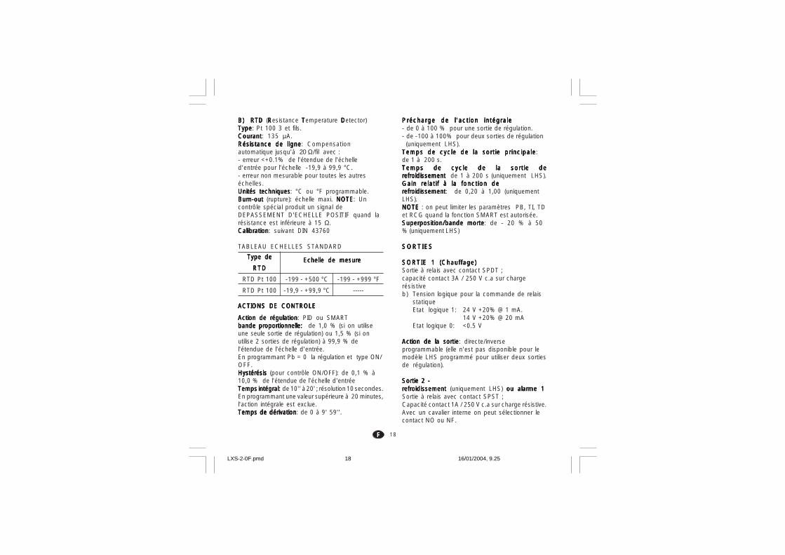
18FFFFF
B) RTDB) RTDB) RTDB) RTDB) RTD (RRRRResistance TTTTTemperature DDDDDetector)TypeTypeTypeTypeType: Pt 100 3 et fils.CourantCourantCourantCourantCourant: 135 µA.Résistance de ligneRésistance de ligneRésistance de ligneRésistance de ligneRésistance de ligne: Compensationautomatique jusqu'à 20 Ω/fil avec :- erreur <+0.1% de l'étendue de l'échelled'entrée pour l'échelle -19,9 à 99,9 °C.- erreur non mesurable pour toutes les autreséchelles.Unités techniquesUnités techniquesUnités techniquesUnités techniquesUnités techniques: °C ou °F programmable.Burn-outBurn-outBurn-outBurn-outBurn-out (rupture): échelle maxi. NOTE NOTE NOTE NOTE NOTE: Uncontrôle spécial produit un signal deDEPASSEMENT D'ECHELLE POSITIF quand larésistance est inférieure à 15 Ω.CalibrationCalibrationCalibrationCalibrationCalibration: suivant DIN 43760
TABLEAU ECHELLES STANDARD
ACTIONS DE CONTROLEACTIONS DE CONTROLEACTIONS DE CONTROLEACTIONS DE CONTROLEACTIONS DE CONTROLE
Action de régulationAction de régulationAction de régulationAction de régulationAction de régulation: PID ou SMARTbande proportionnelle: bande proportionnelle: bande proportionnelle: bande proportionnelle: bande proportionnelle: de 1,0 % (si on utiliseune seule sortie de régulation) ou 1,5 % (si onutilise 2 sorties de régulation) à 99,9 % del'étendue de l'échelle d'entrée.En programmant Pb = 0 la régulation et type ON/OFF.Hystérésis Hystérésis Hystérésis Hystérésis Hystérésis (pour contrôle ON/OFF): de 0,1 % à10,0 % de l'étendue de l'échelle d'entréeTemps intégral: Temps intégral: Temps intégral: Temps intégral: Temps intégral: de 10'' à 20' ; résolution 10 secondes.En programmant une valeur supérieure à 20 minutes,l'action intégrale est exclue.Temps de dérivationTemps de dérivationTemps de dérivationTemps de dérivationTemps de dérivation: de 0 à 9' 59''.
Précharge de l'action intégralePrécharge de l'action intégralePrécharge de l'action intégralePrécharge de l'action intégralePrécharge de l'action intégrale- de 0 à 100 % pour une sortie de régulation.- de -100 à 100% pour deux sorties de régulation (uniquement LHS).Temps de cycle de la sortie principaleTemps de cycle de la sortie principaleTemps de cycle de la sortie principaleTemps de cycle de la sortie principaleTemps de cycle de la sortie principale:de 1 à 200 s.Temps de cycle de la sortie deTemps de cycle de la sortie deTemps de cycle de la sortie deTemps de cycle de la sortie deTemps de cycle de la sortie derefroidissement refroidissement refroidissement refroidissement refroidissement de 1 à 200 s (uniquement LHS).Gain relatif à la fonction deGain relatif à la fonction deGain relatif à la fonction deGain relatif à la fonction deGain relatif à la fonction derefroidissementrefroidissementrefroidissementrefroidissementrefroidissement: de 0,20 à 1,00 (uniquementLHS).NOTE NOTE NOTE NOTE NOTE : on peut limiter les paramètres PB, TI, TDet RCG quand la fonction SMART est autorisée.Superposition/bande morteSuperposition/bande morteSuperposition/bande morteSuperposition/bande morteSuperposition/bande morte: de - 20 % à 50% (uniquement LHS)
SORTIESSORTIESSORTIESSORTIESSORTIES
SORTIE 1 (Chauffage)SORTIE 1 (Chauffage)SORTIE 1 (Chauffage)SORTIE 1 (Chauffage)SORTIE 1 (Chauffage)Sortie à relais avec contact SPDT ;capacité contact 3A / 250 V c.a sur chargerésistiveb) Tension logique pour la commande de relais
statiqueEtat logique 1: 24 V +20% @ 1 mA.
14 V +20% @ 20 mAEtat logique 0: <0.5 V
Action de la sortieAction de la sortieAction de la sortieAction de la sortieAction de la sortie: directe/inverseprogrammable (elle n'est pas disponible pour lemodèle LHS programmé pour utiliser deux sortiesde régulation).
Sortie 2 -Sortie 2 -Sortie 2 -Sortie 2 -Sortie 2 -refroidissement refroidissement refroidissement refroidissement refroidissement (uniquement LHS) ou alarme 1ou alarme 1ou alarme 1ou alarme 1ou alarme 1Sortie à relais avec contact SPST ;Capacité contact 1A / 250 V c.a sur charge résistive.Avec un cavalier interne on peut sélectionner lecontact NO ou NF.
Type deType deType deType deType de
RTDRTDRTDRTDRTD
RTD Pt 100
RTD Pt 100
-199 - +500 °C
-19,9 - +99,9 °C
Echelle de mesureEchelle de mesureEchelle de mesureEchelle de mesureEchelle de mesure
-199 - +999 °F
-----
LXS-2-0F.pmd 16/01/2004, 9.2518

19FFFFF
ENTRETIENENTRETIENENTRETIENENTRETIENENTRETIEN1) COUPER L'ALIMENTATION DE
L'INSTRUMENT(alimentation, sorties à relais,etc.)
2) Extraire l'instrument de son boîtier3) En utilisant un aspirateur ou un jet d'air
comprimé à basse pression (maxi. 3 kg/cm2)
enlever tout dépôt de poussière dans lesfentes de ventilation et sur les circuits enfaisant attention à ne pas endommager lescomposants.
4) Pour nettoyer les parties extérieures enplastique ou en caoutchouc, utiliserexclusivement un chiffon propre et humideavec:- alcool éthylique (pur ou dénaturé) [C2H5OH]-alcool isopropylique (pur ou dénaturé)[(CH3)2CHOH]- Eau (H2O)
5) Contrôler que les bornes sont parfaitemet ser-rées.
6) Avant de brancher l'instrument dans sonboîtier, vérifier qu'il est parfaitement sec.
7) Brancher l'appareil.
LXS-2-0F.pmd 16/01/2004, 9.2519

1DDDDD
Abb. 1
MONTAGEMONTAGEMONTAGEMONTAGEMONTAGEEine saubere, auch an der Rückseite gut zugänglicheund wenn möglich vibrationsfreie Montagestellewählen.Die Umgebungstemperatur muß zwischen 0°C und50 °C liegen.Das Gerät kann auf eine bis zu 15 mm dickeFronttafel montiert werden, in die ein viereckigerAusschnitt mit den Maßen 45 x 45 mm praktiziertwurde.Abmessungen und Fronttafelausschnitt siehe seiteIV.Die Oberflächenrauheit der Tafel muß besser als6,3 µm sein.Das Gerät ist mit einer Gummidichtung für Fronttafelnausgerüstet (von 50 bis 60 Sh).Zur Gewährleistung der Schutzarten IP65 und NEMA4, die mit dem Gerät gelieferte Dichtung zwischendas Gerät und die Tafel einfügen (siehe Abbildung1).Bei der Befestigung des Geräts an der Tafel wiefolgt vorgehen:1) Die Dichtung an dem Gehäuse des Geräts
anbringen.2) Das Gerät in den Ausschnitt einsetzen.3) Das Gerät gut an der Tafel anliegend festhalten
und die Befestigungsstrebe einfügen.4) Mit einem Schraubenzieher die Schrauben mit
einem Anziehmoment zwischen 0,3 und 0,4 Nmfestziehen.
Fronttafel
StrebeSchraube
Dichtung
Abb. 2
LXS-3-0F.pmd 16/01/2004, 9.331
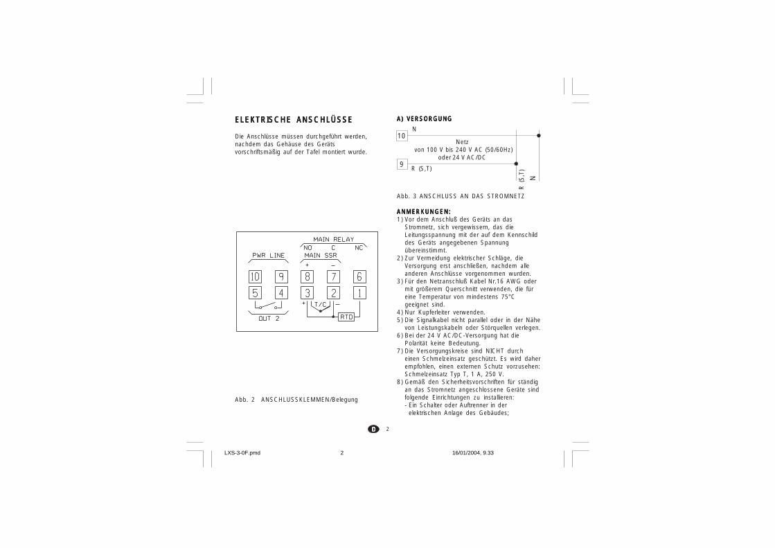
2DDDDD
ELEKTRISCHE ANSCHLÜSSEELEKTRISCHE ANSCHLÜSSEELEKTRISCHE ANSCHLÜSSEELEKTRISCHE ANSCHLÜSSEELEKTRISCHE ANSCHLÜSSE
Die Anschlüsse müssen durchgeführt werden,nachdem das Gehäuse des Gerätsvorschriftsmäßig auf der Tafel montiert wurde.
Abb. 2 ANSCHLUSSKLEMMEN/Belegung
A) VERSORGUNGA) VERSORGUNGA) VERSORGUNGA) VERSORGUNGA) VERSORGUNG
Abb. 3 ANSCHLUSS AN DAS STROMNETZ
ANMERKUNGEN:ANMERKUNGEN:ANMERKUNGEN:ANMERKUNGEN:ANMERKUNGEN:1) Vor dem Anschluß des Geräts an das
Stromnetz, sich vergewissern, das dieLeitungsspannung mit der auf dem Kennschilddes Geräts angegebenen Spannungübereinstimmt.
2) Zur Vermeidung elektrischer Schläge, dieVersorgung erst anschließen, nachdem alleanderen Anschlüsse vorgenommen wurden.
3) Für den Netzanschluß Kabel Nr.16 AWG odermit größerem Querschnitt verwenden, die füreine Temperatur von mindestens 75°Cgeeignet sind.
4) Nur Kupferleiter verwenden.5) Die Signalkabel nicht parallel oder in der Nähe
von Leistungskabeln oder Störquellen verlegen.6) Bei der 24 V AC/DC-Versorgung hat die
Polarität keine Bedeutung.7) Die Versorgungskreise sind NICHT durch
einen Schmelzeinsatz geschützt. Es wird daherempfohlen, einen externen Schutz vorzusehen:Schmelzeinsatz Typ T, 1 A, 250 V.
8) Gemäß den Sicherheitsvorschriften für ständigan das Stromnetz angeschlossene Geräte sindfolgende Einrichtungen zu installieren:- Ein Schalter oder Auftrenner in der
elektrischen Anlage des Gebäudes;
9
R (
S,T
)R (S,T)
N
10N
Netz von 100 V bis 240 V AC (50/60Hz)
oder 24 V AC/DC
LXS-3-0F.pmd 16/01/2004, 9.332

3DDDDD
geeignetes, vorzugsweise abgeschirmtesKompensations-/Erweiterungskabelverwenden.
3) Bei Verwendung eines Abschirmkabels, denSchutzschirm nur an einem Ende erden.
EINGANG FÜREINGANG FÜREINGANG FÜREINGANG FÜREINGANG FÜRWIDERSTANDSTHERMOMETERWIDERSTANDSTHERMOMETERWIDERSTANDSTHERMOMETERWIDERSTANDSTHERMOMETERWIDERSTANDSTHERMOMETER
Abb. 5 ANSCHLUSS VONWIDERSTANDSTHERMOMETERN
ANMERKUNGEN:ANMERKUNGEN:ANMERKUNGEN:ANMERKUNGEN:ANMERKUNGEN:1) Die Signalkabel nicht parallel oder in der Nähe
von Leistungskabeln oder Störquellenverlegen.
2) Auf den Leitungswiderstand achten. Einübermäßig hoher Leitungswiderstand (über20 Ω/Leiter) kann Meßfehler bewirken.
3) Bei Verwendung eines Abschirmkabels, denSchutzschirm nur an einem Ende erden.
4) Die drei Leiter müssen den gleichenWiderstand haben.
- Der Auftrenner muß in unmittelbarer Nähe desGerätes an einer für das Bedienungspersonalleicht zugänglichen Stelle installiert werden.
- Der Schalter muß als Trennvorrichtung desGerätes gekennzeichnet werden.
ANMERKUNG:ANMERKUNG:ANMERKUNG:ANMERKUNG:ANMERKUNG: Ein Schalter oder Auftrenner kannmehrere Geräte steuern.
B) MESSEINGÄNGEB) MESSEINGÄNGEB) MESSEINGÄNGEB) MESSEINGÄNGEB) MESSEINGÄNGEANMERKUNG: ANMERKUNG: ANMERKUNG: ANMERKUNG: ANMERKUNG: Externe Komponenten (z.Bsp.:Zener-Barrieren) zwischen dem Fühler und denEingangsklemmen des Geräts können Meßfehlerbewirken, die durch einen zu hohen oder nichtausbalancierten Widerstand oder durchLeckströme verursacht werden.
EINGANG FÜR THERMOELEMENT (TC)EINGANG FÜR THERMOELEMENT (TC)EINGANG FÜR THERMOELEMENT (TC)EINGANG FÜR THERMOELEMENT (TC)EINGANG FÜR THERMOELEMENT (TC)
Abb. 4 ANSCHLUß VON THERMOELEMENRTENANMERKUNGEN:ANMERKUNGEN:ANMERKUNGEN:ANMERKUNGEN:ANMERKUNGEN:1) Die Signalkabel nicht parallel oder in der Nähe
von Leistungskabeln oder Störquellen verlegen.2) Für den Anschluß des Thermoelements ein
3
2
+
_
3
2
+
_
Schutzschirm
Schutzschirm
1
RTD
32 1
RTD
32
LXS-3-0F.pmd 16/01/2004, 9.333

4DDDDD
Die folgenden Empfehlungen dienen zurVermeidung schwerwiegender Probleme durchdie Verwendung der Relaisausgänge für dieVorsteuerung induktiver Belastungen.
INDUKTIVE BELASTUNGENINDUKTIVE BELASTUNGENINDUKTIVE BELASTUNGENINDUKTIVE BELASTUNGENINDUKTIVE BELASTUNGEN
Bei der Umschaltung induktiver Belastungen könnenEinschwingzustände und Störungen entstehen, diedie Leistungen des Geräts beeinträchtigen können.Die inneren Schutzvorrichtungen (Varistoren)gewährleisten den Schutz gegen Störungen fürLasten mit einer induktiven Komponente bis zu 0,5 A.Analoge Probleme können durch die Umschaltungvon Belastungen mittels eines externen, zumAusgangkontakt des Geräts in Reihe geschaltetenKontakts, entstehen oder durch die Verwendungdes NC-Kontakts des Ausgangs 1.
Abb.7 EXTERNER, ZUM AUSGANGSKONTAKTDES GERÄTS IN REIHE GESCHALTETERKONTAKT
In diesen Fällen wird empfohlen, parallel zumexternen Kontakt einen RC-Filter anzuschließenwie in Abb.7 gezeigt.Der Wert der Kapazität (C) und desWiderstands(R) sind in der folgenden Tabelleangegeben.
RELAISAUSGÄNGERELAISAUSGÄNGERELAISAUSGÄNGERELAISAUSGÄNGERELAISAUSGÄNGE
Abb. 6 ANSCHLUSS DER RELAISAUSGÄNGEDer NO-Kontakt des Ausgangs 1 und derKontakts des Ausgangs 2 sind mittels Varistorengegen Belastungen geschützt, deren induktiveKomponente bis zu 0,5 A beträgt.Die Belastbarkeit des dem Ausgang 1entsprechenden Kontakts, beträgt 3A/250 V ACbei ohmscher Belastung.Die Belastbarkeit der den Ausgängen 2entsprechenden Kontakte, beträgt 1A/250 V ACbei ohmscher Belastung.Die Anzahl der Schaltungen entspricht derspezifizierten Belastbarkeit mal 105.
ANMERKUNGENANMERKUNGENANMERKUNGENANMERKUNGENANMERKUNGEN:1) Um der Gefahr elektrischer Schläge vorzubeugen,
das Netzkabel erst anschließen, nachdem alleanderen Anschlüsse vorgenommen wurden.
2) Für den Netzanschluß, Kabel Nr.16 AWG oder mitgrößerem Querschnitt verwenden, die fürTemperaturen bis mindestens 75°C geeignet sind.
3) Nur Kupferleiter verwenden.4) Die Signalkabel nicht parallel oder in der Nähe
von Leistungskabeln oder Störquellen verlegen.
8
6
7C
NC
NO
OUT 1
4
5C
NO
OUT 2
C R
LOAD
POWERLINE
LXS-3-0F.pmd 16/01/2004, 9.334
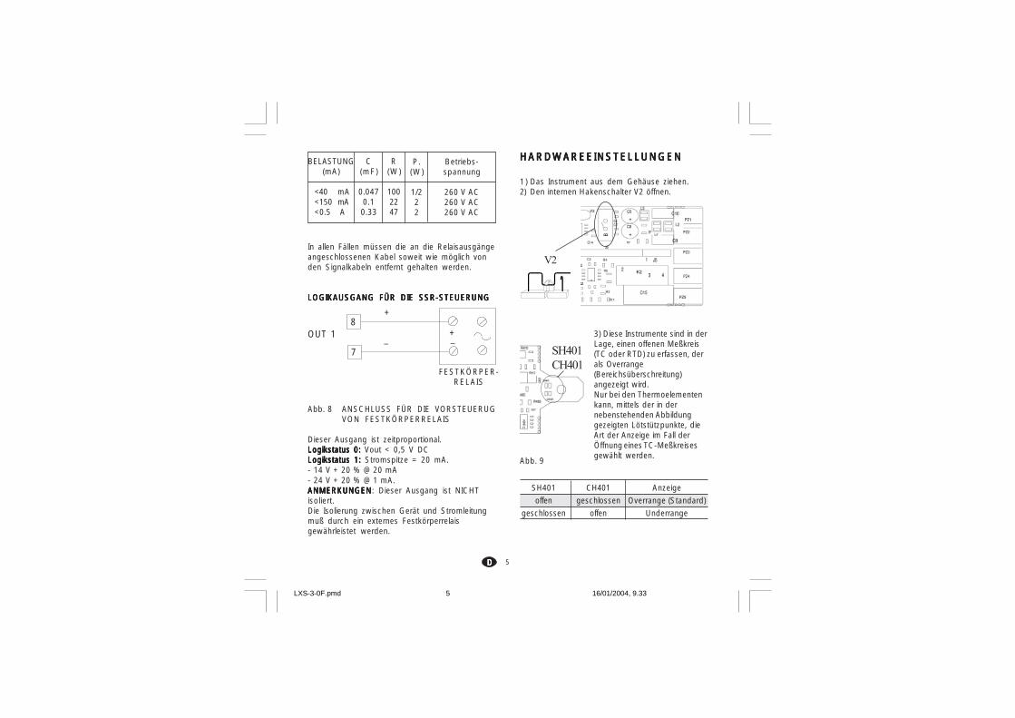
5DDDDD
In allen Fällen müssen die an die Relaisausgängeangeschlossenen Kabel soweit wie möglich vonden Signalkabeln entfernt gehalten werden.
LOGIKAUSGANG FÜR DIE SSR-STEUERUNGLOGIKAUSGANG FÜR DIE SSR-STEUERUNGLOGIKAUSGANG FÜR DIE SSR-STEUERUNGLOGIKAUSGANG FÜR DIE SSR-STEUERUNGLOGIKAUSGANG FÜR DIE SSR-STEUERUNG
Abb. 8 ANSCHLUSS FÜR DIE VORSTEUERUGVON FESTKÖRPERRELAIS
Dieser Ausgang ist zeitproportional.Logikstatus 0:Logikstatus 0:Logikstatus 0:Logikstatus 0:Logikstatus 0: Vout < 0,5 V DCLogikstatus 1:Logikstatus 1:Logikstatus 1:Logikstatus 1:Logikstatus 1: Stromspitze = 20 mA.- 14 V + 20 % @ 20 mA- 24 V + 20 % @ 1 mA.ANMERKUNGENANMERKUNGENANMERKUNGENANMERKUNGENANMERKUNGEN: Dieser Ausgang ist NICHTisoliert.Die Isolierung zwischen Gerät und Stromleitungmuß durch ein externes Festkörperrelaisgewährleistet werden.
HARDWAREEINSTELLUNGENHARDWAREEINSTELLUNGENHARDWAREEINSTELLUNGENHARDWAREEINSTELLUNGENHARDWAREEINSTELLUNGEN
1) Das Instrument aus dem Gehäuse ziehen.2) Den internen Hakenschalter V2 öffnen.
3) Diese Instrumente sind in derLage, einen offenen Meßkreis(TC oder RTD) zu erfassen, derals Overrange(Bereichsüberschreitung)angezeigt wird.Nur bei den Thermoelementenkann, mittels der in dernebenstehenden Abbildunggezeigten Lötstützpunkte, dieArt der Anzeige im Fall derÖffnung eines TC-Meßkreisesgewählt werden.
SH401 CH401 Anzeige
offen geschlossen Overrange (Standard)
geschlossen offen Underrange
Abb. 9
+
_ _+
8
7
OUT 1
FESTKÖRPER-RELAIS
BELASTUNG(mA)
<40 mA<150 mA<0.5 A
C(mF)
0.0470.10.33
R(W)
1002247
P.(W)
1/222
Betriebs-spannung
260 V AC260 V AC260 V AC
V2
SH401CH401
LXS-3-0F.pmd 16/01/2004, 9.335

6DDDDD
4) Wenn das Gerät für die Anzeige in °Fprogrammiert wurde, das auf der Seite desINHALTSVERZEICHNISSES angebrachte,zusätzliche Etikett auf der Vorderseite desGeräts anbringen, so daß es das vorhandeneSchild mit der physikalischen Einheit °Cüberdeckt.
5) Das Gerät in das Gehäuse zurückschieben.6) Das Gerät mit Strom versorgen.
Auf der Anzeige erscheint “CnF”.ACHTUNG:ACHTUNG:ACHTUNG:ACHTUNG:ACHTUNG: Falls auf der Anzeige die Schrift“CAL” erscheint, sofort die Taste drückenund zur Konfiguration zurückkehren.
7) Die Taste FN drücken.Bei den Geräten LMS-LHS erscheint auf derunteren Anzeige (Display) der Code desangewählten Parameters, während das obereDisplay den eingestellten Wert anzeigt.Bei dem Gerät LDS werden der Code desParameters und der entsprechende Wertabwechselnd angezeigt.
ALLGEMEINE ANMERKUNGENALLGEMEINE ANMERKUNGENALLGEMEINE ANMERKUNGENALLGEMEINE ANMERKUNGENALLGEMEINE ANMERKUNGENzur Konfigurationzur Konfigurationzur Konfigurationzur Konfigurationzur KonfigurationFN = Speichern der eingestellten Werte und
Anwahl des darauf folgendenParameters.
ST = Rückwärtstasten der Parameter,jedoch keine Speicherung.
= Vergrößern des Wertes desangewählten Parameters
= Verkleinern des Wertes desangewählten Parameters
°F°F°F°F°F
KONFIGURATIONSVERFAHRENKONFIGURATIONSVERFAHRENKONFIGURATIONSVERFAHRENKONFIGURATIONSVERFAHRENKONFIGURATIONSVERFAHREN
P1 - Art des Eingangs und StandardskalaP1 - Art des Eingangs und StandardskalaP1 - Art des Eingangs und StandardskalaP1 - Art des Eingangs und StandardskalaP1 - Art des Eingangs und Standardskala0 = TC-Art L Bereich 0 / +800 °C1 = TC-Art J Bereich 0 / +800 °C2 = TC-Art K Bereich 0 / +999 °C3 = TC-Art N Bereich 0 / +999 °C4 = RTD-Art Pt 100 Bereich -199 / +500 °C5 = RTD-Art Pt 100 Bereich -19.9 / +99.9 °C6 = TC-Art T Bereich 0 / +400 °C8 = TC-Art L Bereich 0 / +999 °F9 = TC-Art J Bereich 0 / +999 °F10 = TC-Art K Bereich 0 / +999 °F11 = TC-Art N Bereich 0 / +999 °F12 = RTD-Art Pt 100 Bereich -199 / +999 °F13 = TC-Art T Bereich 0 / +752 °FTC = Thermoelement RTD = Widerstandsthermometer
ANMERKUNG:ANMERKUNG:ANMERKUNG:ANMERKUNG:ANMERKUNG: Für die Meßbereiche in °F steht einKlebeetikett mit der Aufschrift “°F” zur Verfügung,das an der Vorderseite des Geräts anzubringen ist.Das o.a. Etikett, das über dem Titel “INHALTS-VERZEICHNIS” angebracht ist, muß über die °C-Anzeige geklebt werden.
P2 - AnfangswertP2 - AnfangswertP2 - AnfangswertP2 - AnfangswertP2 - AnfangswertNicht verfügbar, wenn P1 = 5.Vom Algorithmus PID benutzter Anfangswert fürdie Berechnungen des Breite desArbeitsbereichs.
P3 - EndwertP3 - EndwertP3 - EndwertP3 - EndwertP3 - EndwertNicht verfügbar, wenn P1 = 5.Vom Algorithmus PID benutzter Endwert.ANMERKUNGEN:ANMERKUNGEN:ANMERKUNGEN:ANMERKUNGEN:ANMERKUNGEN:1) Die Breite des eingestellten Arbeitsbereiches
(P3 - P2) muß bei Thermoelement-Eingängenüber 300 °C oder 600 °F liegen, bzw. bei 100 °Coder 200 °F bei Eingängen von Widerstands-thermometern.
2) Bei einer Änderung des Wertes von P3 und/oderP4, werden die Parameter rL und rH automatischdem neuen Wert von P3 bzw. P4 angepaßt.
LXS-3-0F.pmd 16/01/2004, 9.336

7DDDDD
t
Eingang
t
Ausgang
t
Eingang
t
Ausgang
Indirekt Direkt
P4 - Regelverhalten des HauptausgangsP4 - Regelverhalten des HauptausgangsP4 - Regelverhalten des HauptausgangsP4 - Regelverhalten des HauptausgangsP4 - Regelverhalten des HauptausgangsBei dem Gerät LHS wird dieser Parameter nichtangezeigt, wenn P5 = 5.r = indirektes Regelverhalten (Heizen)d = direktes Regelverhalten (Kühlen)
P5 - Funktion desAusgangs 2P5 - Funktion desAusgangs 2P5 - Funktion desAusgangs 2P5 - Funktion desAusgangs 2P5 - Funktion desAusgangs 20= Nicht vorgesehen1 = Vollbereichsalarm2 = Bandalarm3 = Abweichungsalarm4 = Eingangssignalüberwachung5 = Kühlausgang (nur LHS)ANMERKUNG:ANMERKUNG:ANMERKUNG:ANMERKUNG:ANMERKUNG: Nur beim Gerät LHS, nimmt derParameter P4 automatisch den Wert “r” an, wennP5 =5.
P6 - Wirkungsweise des Ausgangs 2P6 - Wirkungsweise des Ausgangs 2P6 - Wirkungsweise des Ausgangs 2P6 - Wirkungsweise des Ausgangs 2P6 - Wirkungsweise des Ausgangs 2P6 wird nicht angezeigt, wenn P5 =0.
Wenn P5 = 1,2 oder 3H.A.= Maximumalarm (außerhalb des Bandes) mit
automatischer Rücksetzung.L.A. = Minimumalarm (innerhalb des Bandes) mit
automatischer Rücksetzung.H.L. = Maximumalarm (außerhalb des Bandes) mit
manuellem Rücksetzen.L.L. = Minimumalarm (innerhalb des Bandes) mit
manuellem Rücksetzen.Wenn P5 = 4, zeigen H.A. und L.A. einen Heizleiter-bruch-Alarm mit automatischer Rücksetzung an,während H.L und L.L. einen Heizleiterbruchalarm mitmanuellem Rücksetzen anzeigen.
Wenn P5 = 5 wählt dieser Parameter die Art desKühlmediums.AIr = Luft OIL = OI H2O = Wasser
ANMERKUNG:ANMERKUNG:ANMERKUNG:ANMERKUNG:ANMERKUNG: Die Änderung der Art desKühlmediums bewirkt die automatischeAnpassung der Zeit der Kühlverstärkung und derKühlverstärkung.
P6 C RCGAIr 10 (s) 1OIL 4 (s) 0.8H2O 2 (s) 0.4
P7 - Wirkung des AlarmsP7 - Wirkung des AlarmsP7 - Wirkung des AlarmsP7 - Wirkung des AlarmsP7 - Wirkung des AlarmsNur verfügbar, wenn P5 nicht 0 oder 5 ist.r = indirekt (Relais bei Alarm abgefallen)d = direkt (Relais bei Alarm angezogen)
P8 = P8 = P8 = P8 = P8 = Unterdrückung des Alarms Unterdrückung des Alarms Unterdrückung des Alarms Unterdrückung des Alarms Unterdrückung des AlarmsNur verfügbar, wenn P5 gleich 1,2,oder 3 ist.
OFF = Unterdrückung deaktiviert.ON = Unterdrückung aktiviert.
ANMERKUNG: ANMERKUNG: ANMERKUNG: ANMERKUNG: ANMERKUNG: Die Unterdrückung ermöglichtden Ausschluß der Alarme bei der Einschaltungdes Geräts und nach Änderungen des Sollwerts;die Alarme werden automatisch wieder aktiviert,sobald der Istwert sich wieder innerhalb derGrenzwerte befindet.
P9 =P9 =P9 =P9 =P9 = Meßwertkorrektur (OFFSET)Meßwertkorrektur (OFFSET)Meßwertkorrektur (OFFSET)Meßwertkorrektur (OFFSET)Meßwertkorrektur (OFFSET)Dieser Parameter ermöglicht die Einstellung eineskonstanten OFFSET im gesamten Meßbereich:Wenn P1 = 5: P9 kann von -19,9 bis 19,9 °C
eingestellt werden.Wenn P1 # 5 : P9 kann von -199 bis 199°C
eingestellt werden.
LXS-3-0F.pmd 16/01/2004, 9.337

8DDDDD
P10 = “Soft Start”-SchaltschwelleP10 = “Soft Start”-SchaltschwelleP10 = “Soft Start”-SchaltschwelleP10 = “Soft Start”-SchaltschwelleP10 = “Soft Start”-SchaltschwelleDie “Soft Start”-Funktion ermöglicht bei der Ein-schaltung des Geräts, falls der Meßwert untereinem festgelegten Schwellenwert liegt, die Be-grenzung der Ausgangsleistung (siehe Betriebs-parameter OLH) während einer einstell-barenZeitspanne (siehe Betriebsparameter tOL).P10 ist die Schaltschwelle, in physikalischenEinheiten, für die “Soft Start”-Funktion.
P11 - Zugriff auf die RegelparameterP11 - Zugriff auf die RegelparameterP11 - Zugriff auf die RegelparameterP11 - Zugriff auf die RegelparameterP11 - Zugriff auf die Regelparameter0 = Verriegelung deaktiviert. Alle Parameter
können geändert werden.1 = Verriegelung deaktiviert.Kein Parameter,
mit Ausnahme des Sollwerts, kanngeändert werden.Von 2 bis 499 = SP kann immer geândertwerden;Stellen die Geheimnummer (zu erin-nern) ein, die während des Betriebsmodusdie Verriegelung zu aktivieren/deaktivieren.Während des Betriebs zeigt das Gerätfolgendes an:
A ) Die Verriegelung ist deaktiviertund alle Parameter könnengeändert werden. ZurAktivierung der Verriegelungund zur Sicherung derParameter, genügt es, eineNummer einzugeben, die sichvon der “Geheimnummer”unterscheidet.
B) Die Verriegelung ist aktiviert undkein Parameter, mit Ausnahmedes Sollwerts, kann geändertwerden.Zur Deaktivierung derVerriegelung und Freigabe derÄnderung der Parameter,genügt es, die ”Geheim-nummer” einzugeben.
Wird eine Geheimnummer zwischen 500 und 999eingestellt, verhält das Gerät sich wie obenbeschrieben, aber ermöglicht die Änderungdes Sollwerts und der Alarmschaltschwellebei aktivierter Verriegelung.
P12 - Höchstgeschwindigkeit der ÄnderungP12 - Höchstgeschwindigkeit der ÄnderungP12 - Höchstgeschwindigkeit der ÄnderungP12 - Höchstgeschwindigkeit der ÄnderungP12 - Höchstgeschwindigkeit der Änderungdes Ausgangssignalsdes Ausgangssignalsdes Ausgangssignalsdes Ausgangssignalsdes Ausgangssignals
Dieser Parameter ist verfügbar, wenn Pb nicht 0 ist.Von 1 bis 100% des Ausgangssignals proSekunde einstellbar.Über 10%/s erscheint auf dem Display die Schrift“InF, die den Ausschluß der Begrenzung anzeigt.
P13 - Auflösung des Abweichungs-BargraphP13 - Auflösung des Abweichungs-BargraphP13 - Auflösung des Abweichungs-BargraphP13 - Auflösung des Abweichungs-BargraphP13 - Auflösung des Abweichungs-Bargraph(nur LDS)(nur LDS)(nur LDS)(nur LDS)(nur LDS)
Für den Widerstandsthermometer-Eingang mitDezimalziffer, kann P13 von 0,2 bis 20,0 °Ceingestellt werden.Für alle anderen Eingänge kann P13 auf 2 bis200 physikalische Einheiten eingestellt werden.
Die Primärkonfiguration ist abgeschlossen unddas Gerät zeigt auf beiden Displays“ -.-.-. “ an.Für den Zugriff auf die sekundärenKonfigurationsparameter, wie folgt vorgehen:1) Mit Hilfe der Tasten und den Code 219
einstellen.2) Die Taste FN drücken.
Falls das Konfigurationsverfahren beendetwerden soll, die Taste FN drücken; das Displayzeigt “CnF” an.
Reale KurveAnzeige
modifizierteKurve
Eingang
P9
O F FO F FO F FO F FO F Fn n nn n nn n nn n nn n n
O NO NO NO NO N
n n nn n nn n nn n nn n n
LXS-3-0F.pmd 16/01/2004, 9.338
9DDDDD
P14 -P14 -P14 -P14 -P14 - Aktivierung/Deaktivierung der AnzeigeAktivierung/Deaktivierung der AnzeigeAktivierung/Deaktivierung der AnzeigeAktivierung/Deaktivierung der AnzeigeAktivierung/Deaktivierung der Anzeigeder geschützten Parameterder geschützten Parameterder geschützten Parameterder geschützten Parameterder geschützten Parameter
Dieser Parameter ist verfügbar, wenn P11 nicht 0ist.Dieser Parameter ermöglicht die Anzeige dergeschützten Parameter während des Betriebs.OFF = Die geschützten Parameter können nichtangezeigt werden.ON = Die geschützten Parameter könnenangezeigt werden.
P15 -P15 -P15 -P15 -P15 - Aktivierung/Deaktivierung der SMART-Aktivierung/Deaktivierung der SMART-Aktivierung/Deaktivierung der SMART-Aktivierung/Deaktivierung der SMART-Aktivierung/Deaktivierung der SMART-FunktionFunktionFunktionFunktionFunktion
0 = Die SMART-Funktion istdeaktiviert
1 = Die Aktivierung/Deaktivierungder SMART-Funktion ist NICHTduerch den Sicherungscodegeschützt
2 = Dia Aktivierung/Deaktivierungder SMART-Funktion ist durchden Sicherungscodegeschützt.
P16 -P16 -P16 -P16 -P16 - Automatisch von der SMART-FunktionAutomatisch von der SMART-FunktionAutomatisch von der SMART-FunktionAutomatisch von der SMART-FunktionAutomatisch von der SMART-Funktioneinstellbarer max. Wert des Propor-einstellbarer max. Wert des Propor-einstellbarer max. Wert des Propor-einstellbarer max. Wert des Propor-einstellbarer max. Wert des Propor-tionalbandes.tionalbandes.tionalbandes.tionalbandes.tionalbandes.
Dieser Parameter kann die zwischen P17 oderP18 liegenden Werte und den Wert 99,9annehmen.
P17 -P17 -P17 -P17 -P17 - Automatisch von der SMART-FunktionAutomatisch von der SMART-FunktionAutomatisch von der SMART-FunktionAutomatisch von der SMART-FunktionAutomatisch von der SMART-Funktioneinstellbarer min.Wert des Propor-einstellbarer min.Wert des Propor-einstellbarer min.Wert des Propor-einstellbarer min.Wert des Propor-einstellbarer min.Wert des Propor-tionalbandes bei Geräten mit einemtionalbandes bei Geräten mit einemtionalbandes bei Geräten mit einemtionalbandes bei Geräten mit einemtionalbandes bei Geräten mit einemeinzigen Regelausgang.einzigen Regelausgang.einzigen Regelausgang.einzigen Regelausgang.einzigen Regelausgang.
Dieser Parameter wird nur angezeigt, wenn P5 nicht 5ist.P17 kann die Werte zwischen 1,0% und dem Wert P16annehmen.
P18 -P18 -P18 -P18 -P18 -Automatisch von der SMART-Automatisch von der SMART-Automatisch von der SMART-Automatisch von der SMART-Automatisch von der SMART-Funktion einstel lbarer min.Wert desFunktion einstel lbarer min.Wert desFunktion einstel lbarer min.Wert desFunktion einstel lbarer min.Wert desFunktion einstel lbarer min.Wert desProportionalbandes bei Geräten mitProportionalbandes bei Geräten mitProportionalbandes bei Geräten mitProportionalbandes bei Geräten mitProportionalbandes bei Geräten mitzwei Regelausgängen (LHS)zwei Regelausgängen (LHS)zwei Regelausgängen (LHS)zwei Regelausgängen (LHS)zwei Regelausgängen (LHS)
Dieser Parameter wird nur angezeigt, wenn P5gleich 5 ist.P18 kann die Werte zwischen 1,5% und demWert von P16 annehmen.
P19 -P19 -P19 -P19 -P19 - Automatische Berechnung der Automatische Berechnung der Automatische Berechnung der Automatische Berechnung der Automatische Berechnung der“relativen Kühlverstärkung” (LHS)“relativen Kühlverstärkung” (LHS)“relativen Kühlverstärkung” (LHS)“relativen Kühlverstärkung” (LHS)“relativen Kühlverstärkung” (LHS)
Dieser Parameter ist nur vorhanden, wenn P5gleich 5 ist.
OFF = Die SMART-Funktion berechnetdie relative KühlverstärkungNICHT.NICHT.NICHT.NICHT.NICHT.
ON = Die SMART-Funktion berechnetdie relative Kühlverstärkung.
P20 -P20 -P20 -P20 -P20 - Mindestwert der von der SMART- Mindestwert der von der SMART- Mindestwert der von der SMART- Mindestwert der von der SMART- Mindestwert der von der SMART-Funktion berechneten IntegralzeitFunktion berechneten IntegralzeitFunktion berechneten IntegralzeitFunktion berechneten IntegralzeitFunktion berechneten Integralzeit
P20 kann Werte annehmen, die zwischen 00,1(10 Sekunden) und 02,0 (2 Minuten) liegen.
P21 = Erweiterung des Anti-reset-wind-upP21 = Erweiterung des Anti-reset-wind-upP21 = Erweiterung des Anti-reset-wind-upP21 = Erweiterung des Anti-reset-wind-upP21 = Erweiterung des Anti-reset-wind-upBereich: Von - 30 bis +30% desProportionalbandes.ANMERKUNG:ANMERKUNG:ANMERKUNG:ANMERKUNG:ANMERKUNG: Ein positiver Wert erhöht diemax. Grenze der Funktion (über den Sollwert),während ein negativer Wert die min. Grenze derFunktion senkt (unter den Sollwert).
An diesem Punkt sind alleKonfigurationsverfahren beendet und das Gerätzeigt “CnF” an.
LXS-3-0F.pmd 16/01/2004, 9.339
10DDDDD
BETRIEBSMODUSVORBEMERKUNGENVORBEMERKUNGENVORBEMERKUNGENVORBEMERKUNGENVORBEMERKUNGENDamit das Gerät als Regler arbeitet, muß derHakenschalter V2 (siehe Abbildung 9)geschlossen sein.
Es wird angenommen, daß das Gerät gemäß denin Abschnitt 3 wiedergegebenen Anweisungenkonfiguriert wurde.
- Die Modelle LMS und LHS zeigen auf dem oberenDisplay den Meßwert an, während das untereDisplay normalerweise zur Anzeige desBetriebssollwerts dient (dieser Zustand wird “nor-male Anzeigeart” genannt.)
- Das Modell LDS zeigt den Meßwert an (“normaleAnzeigeart”) oder den Betriebssollwert (in diesemFall blinkt die LED SP). Zum Übergang von derAnzeige des Sollwerts zur Anzeige des Meßwertsund umgekehrt, die Taste drücken.
Durch Druck auf die Taste FN können alleParameter der Reihe nach durchlaufen werden.- Die Modelle LMS und LHS zeigen auf dem
unteren Display die Abkürzung desangewählten Parameters an, während auf demoberen Display der eingestellte Wert erscheint.
- Das Modell LDS zeigt abwechselnd den Namenund Wert des Parameters an, während es bei derModifizierung nur den Parameterwert anzeigt.
Zur Änderung der Einstellung eines Parameterswie folgt vorgehen:1) Mit der Taste FN den Parameter anwählen, der
geändert werden soll.2) Mit Hilfe der Tasten und den
gewünschten Wert einstellen.3) Die Taste FN drücken, um den neuen Wert zu
speichern und zum nächsten Parameterübergehen.
ANMERKUNGEN:ANMERKUNGEN:ANMERKUNGEN:ANMERKUNGEN:ANMERKUNGEN:1) Falls während der Änderung eines Parameters
länger als 10 Sekunden lang keine Tastegedrückt wird, kehrt das Gerät automatiischzur normalen Anzeigeart zurück und die neueEinstellung des letzten Parameters gehtverloren.
2) Das Gerät zeigt nicht alle möglichen Parameteran, sondern nur jene, die übereinstimmen mit:a) der Konfiguration des Geräts (sieheAbschnitt 3)b) der Einstellung des Parameters P14 (sieheAbschnitt 3)c) der Einstellung des Proportionalbandes(siehe folgende Seite).
ANZEIGERANZEIGERANZEIGERANZEIGERANZEIGERST Blinkt, wenn die SMART-Funktion die
erste Phase der Selbstoptimierungdurchführt.Leuchtet dauernd, wenn die SMART-Funktion die zweite Phase derSelbstoptimierung durchführt.
OUT Leuchtet, wenn der Ausgang 1 in ON-Zustand ist.
ALM/COOL Leuchtet, wenn der Ausgang 2 inON-Zustand oder der Alarm 1 inAlarmzustand ist.
SP (nur LDS) blinkt, wenn das Gerät denSollwert anzeigt.
LXS-3-0F.pmd 16/01/2004, 9.3310

11DDDDD
Beschreibung der TastaturBeschreibung der TastaturBeschreibung der TastaturBeschreibung der TastaturBeschreibung der TastaturFN = Speichern der eingestellten Werte und
Anwahl des darauf folgendenParameters.
ST = Aktivierung/Deaktivierung der SMART-Funktion undRückwärtstasten der Parameter, jedochkeine Speicherung.
= Vergrößern des Wertes des angezeigtenParameters oder, nur bei LDS, Anzeigedes Sollwerts.
= Verkleinern des Wertes des angezeigtenParameters.
+ FN = Aktivierung/Deaktivierung derÜBERPRÜFUNG DERKONTROLLAMPEN.
ANMERKUNG:ANMERKUNG:ANMERKUNG:ANMERKUNG:ANMERKUNG: Für die Änderung derBetriebsparameter ist ein Time out von 10Sekunden festgesetzt. Falls während derÄnderung der Parameter für eine Zeit, die dasTime out überschreitet, keinerlei Taste gedrücktwird, kehrt das Gerät zur normalen Anzeigeartzurück und speichert nur die Änderungen derParameter, die durch Betätigung der Taste FNbestätigt wurden.
MANUELLES RÜCKSETZEN DER ALARMEMANUELLES RÜCKSETZEN DER ALARMEMANUELLES RÜCKSETZEN DER ALARMEMANUELLES RÜCKSETZEN DER ALARMEMANUELLES RÜCKSETZEN DER ALARMEWenn ein Alarm mit manuellem Rücksetzeneingestellt wurde, bleibt die Alarmanzeige auchbestehen, nachdem der Alarmzustand nicht mehrvorliegt.Zum Rücksetzen des Alarms, die Taste FNdrücken und den Parameter “n.rS” anwählen (aufder Anzeige erscheint “n.rS” und “OFF”). Mit denTasten und “ON” anwählen und die TasteFN drücken. Der Alarm kann nur manuellrückgesetzt werden, wenn der Alarmzustand nichtmehr vorliegt.
SMART-ALGORITHMUSSMART-ALGORITHMUSSMART-ALGORITHMUSSMART-ALGORITHMUSSMART-ALGORITHMUSDiese Funktion ermöglicht die automatischeOptimierung der Regelaktion.Zur Aktivierung derSMART-Funktion, während der “normalen Anzeige-art” länger als 1,5 Sekunden lang die Taste STdrücken. Die LED “ST” blinkt oder leuchtet dauernd inFunktion des Algorithmus, den das Gerät ge-wählthat. Wenn die SMART-Funktion aktiviert ist, zeigt dasGerät die her-kömmlichen Regelparameter (PB, TI,TD und rC) an, ermöglicht aber nicht ihre Änderung.Falls zur herkömmlichen Regelaktion (PID)zurückgekehrt werden soll, erneut mindestens 1,5Sekunden lang die Taste ST drücken. Das Gerät hältdie aktuellen Werte der Regelparameter und gibt dieÄnderung der Parameter selbst frei.ANMERKUNGEN:ANMERKUNGEN:ANMERKUNGEN:ANMERKUNGEN:ANMERKUNGEN:1) Wenn die SMART-Funktion aktiviert ist, wird die
relative Kühlverstärkung (falls von der SMART-Funktion geregelt) wie folgt beschränkt:
Kühlmedium BereichAir de 0.85 bis 1.00OIL de 0.80 bis 0.90H2O de 0.30 bis 0.60
2) Die SMART-Funktion verwendet eineDifferentialzeit (Vorhaltezeit), die einem Viertelder integralen Vorspannzeit entspricht.
3) Die Grenzen des proportionalenRegelverhaltens können über die ParameterP16, P17 und P18 eingestellt werden.
4) Wenn die SMART-Funktion aktiviert ist, ist derMindestwert der integralen Vorspannzeit durchden Parameter P20 festgelegt.
5) Wird das Gerät für das Regelverhalten ON/OFF (Pb = 0) programmiert, wird die SMART-Funktion automatisch deaktiviert.
6) Die Aktivierung/Deaktivierung der SMART-Funktion kann durch den Schlüssel für denZugriff auf die Parameter verriegelt werden(siehe Parameter P15).
LXS-3-0F.pmd 16/01/2004, 9.3311
12DDDDD
2) Wenn das Gerät ausgeschaltet wird, während dieSperrfunktion des Ausgangssignals aktiviert ist,wird bei der nächsten Einschaltung des Gerätsdiese Funktion automatisch wieder aktiviert.
DIREKTE ÄNDERUNG DES SOLLWERTSDIREKTE ÄNDERUNG DES SOLLWERTSDIREKTE ÄNDERUNG DES SOLLWERTSDIREKTE ÄNDERUNG DES SOLLWERTSDIREKTE ÄNDERUNG DES SOLLWERTSBei diesen Geräten kann der Sollwert ohneVerwendung der Taste FN geändert werden.Wenn der Sollwert rasch geändert werden soll,wie folgt vorgehen:1) Mehr als 3 Sekunden lang die Taste oder
drücken: Der Wert des Sollwerts beginnt, sichzu ändern.
2) Mit den Tasten und den gewünschtenWert einstellen.
3) Sobald der gewünschte Wert erreicht ist,KEINE Taste drücken. Der neue Wert desSollwerts wird 3 Sekunden nach dem letztenTastendruck wirksam und das Gerät kehrt zur“normalen Anzeigeart” zurück.
Falls während dieses Verfahrens die Änderungnicht gespeichert werden soll, die Taste FNdrücken: Das Gerät kehrt automatisch zur“normalen Anzeigeart” zurück, ohne den neuenSollwert zu speichern.
ANZEIGE DES EINGESTELLTEN SOLLWERTSANZEIGE DES EINGESTELLTEN SOLLWERTSANZEIGE DES EINGESTELLTEN SOLLWERTSANZEIGE DES EINGESTELLTEN SOLLWERTSANZEIGE DES EINGESTELLTEN SOLLWERTS(nur LDS)(nur LDS)(nur LDS)(nur LDS)(nur LDS)Um den eingestellten Sollwert auf dem Displayanzuzeigen, genügt ein Druck auf die Taste .Auf dem Display erscheint der Wert desSollwerts, gefolgt vom Blinken desDezimalpunkts, der sich auf die wenigersignifikante Ziffer bezieht (auf der Fronttafel durchdie Schrift SP angezeigt).Um zur Anzeige des Meßwertes zurückzukehren,erneut die Taste drücken.
SPERRE DES AUSGANGSSIGNALSSPERRE DES AUSGANGSSIGNALSSPERRE DES AUSGANGSSIGNALSSPERRE DES AUSGANGSSIGNALSSPERRE DES AUSGANGSSIGNALSDiese Geräte ermöglichen die manuelle Sperredes Ausgangssignals, um die Regelaktion zublockieren.Zur Sperre des Ausgangssignals die Taste drücken, niederhalten und gleichzeitig mindestens3 Sekunden lang die Taste FN drücken.Das Gerät zeigt anstelle der Anzeige desSollwerts “OFF” an; das Ausgangssignal stelltsich auf OFF und das Gerät funktioniert alseinfaches Anzeigerät.Nur beim Modell LDS kann durch Druck auf dieTaste der Meßwert angezeigt werden, aber diedrei LED des Bargraphs blinken (wodurchangezeigt wird, daß das Gerät als einfachesAnzeigegerät arbeitet).Wenn die Regelausgänge deaktiviert sind, sindauch die Alarme deaktiviert und auf den Zustanddes Fehlens der Alarme modifiziert.Die Änderung der Regelparameter bleibt jedochauf jeden Fall aktiviert.Um das Gerät wieder als Regelinstrument zuverwenden, die Taste drücken, niederhaltenund gleichzeitig mindestens 3 Sekunden lang dieTaste FN drücken.ANMERKUNGEN:ANMERKUNGEN:ANMERKUNGEN:ANMERKUNGEN:ANMERKUNGEN:1) Wenn der Ausgang gesperrt wird, während die
SMART-Funktion die erste Phase derSelbstoptimierung durchführt (die LED ST blinkt),ist die Selbstoptimierungs-Funktion deaktiviert,wenn das Gerät zum normalen Regelverhaltenzurückkehrt.Wenn der Ausgang gesperrt wird, während dieSMART-Funktion auf normale Weise arbeitet(die LED ST leuchtet dauernd), wird dieSMART-Funktion vorübergehend blockiert;wenn das Gerät zum normalen Regelverhaltenzurückkehrt, ist die SMART-Funktion erneutaktiv.
LXS-3-0F.pmd 16/01/2004, 9.3312

13DDDDD
FUNKTION DES BARGRAPHS (NUR LDS)FUNKTION DES BARGRAPHS (NUR LDS)FUNKTION DES BARGRAPHS (NUR LDS)FUNKTION DES BARGRAPHS (NUR LDS)FUNKTION DES BARGRAPHS (NUR LDS)Der 3 LED-Bargraph zeigt eine vorliegendeAbweichung zwischen Meßwert und eingestelltemSollwert an.Die mittlere LED (grün) leuchet, wenn dieAbweichung unter der Hälfte des mittels desParameters P13 eingestellten Werts liegt.Wenn die Abweichung mehr 1/2 P13, aberweniger als 3/2P13 beträgt, leuchtet dieentsprechende rote LED.Falls die Abweichung über 3/2 des Wert von P13liegt, blinkt die entsprechende LED.
ÜBERPRÜFUNG DER KONTROLLAMPENÜBERPRÜFUNG DER KONTROLLAMPENÜBERPRÜFUNG DER KONTROLLAMPENÜBERPRÜFUNG DER KONTROLLAMPENÜBERPRÜFUNG DER KONTROLLAMPEN(LAMP TEST)(LAMP TEST)(LAMP TEST)(LAMP TEST)(LAMP TEST)Falls die Funktionstüchtigkeit der Anzeigerüberprüft werden soll, die Tasten und FNdrücken. Das Gerät schaltet alle LED’s desAnzeigers mit einem duty cicle gleich 50% ein(dieser Status wird LAMP TEST genannt).Für den LAMP TEST ist kein Time outfestgesetzt. Um zur normalen Anzeigeartzurückzukehren, erneut die Tasten und FNdrücken.Während des LAMP TEST’s sind alle anderenFunktionen deaktiviert.
BETRIEBSPARAMETERBETRIEBSPARAMETERBETRIEBSPARAMETERBETRIEBSPARAMETERBETRIEBSPARAMETERDer folgende Abschnitt enthält die vollständigeListe der Regelparameter. Es wird daraufhingewisen, daß einige Parameter in Funktion derspezifischen Konfiguration des Geräts nichtangezeigt werden könnten.Die Taste FUNC drücken: Auf dem unterenDisplay erscheint der Code, während das obereDisplay den Wert des angewählten Parameters
anzeigt.Mit den Tasten Tasten und können der Wertoder der gewünschte Status eingestellt werden.Durch erneuten Druck auf die Taste FUNC,speichert das Gerät den neuen Wert (oder denneuen Status) und geht zur Anzeige desfolgenden Parameters über.Param.BeschreibungSP Sollwert (in physikalischen Einheiten).
Bereich: Von rL bis rH.n.RStManuelles Rücksetzen der Alarme.
Dieser Parameter wird angezeigt, wennzumindest für einen Alarmmanuelles Rücksetzen programmiert wurde.ON einstellen und die Taste FN dücken, umdie Alarme zurückzusetzen.
nnn Sicherungsschlüssel für die Verriegelungder Parameter.Wird nicht angezeigt, wenn P11= oder 1.ON = Die Parameter sind verriegelt.OFF = Die Parameter sind nicht verriegelt.Falls die Verriegelung der Parameterdeaktiviert werden soll, einen Werteinstellen, der dem Wert gleich ist, der demParameter P11 zugeordnet wurde.Wenn die Verriegelung wieder aktiviertwerden soll, einen Wert einstellen,der von dem Wert abweicht, der demParameter P11 zugeordnet wurde.
AL Schaltschwelle des Alarms (inphysikalischen Einheiten).AL1 wird nur angezeigt, wenn der Alarmkonfiguriert wurde.Bereiche:- Innerhalb des Eingangsbereiches (P3-P2)für Vollbereichsalarme.- Von 0 bis 500 Einheiten für Bandalarme.- Von -199 - 500 Einheiten fürAbweichungsalarme.
LXS-3-0F.pmd 16/01/2004, 9.3313

14DDDDD
HSA Alarm-Hysterese (in% des Bereichs P3-P2)HSA wird nur angezeigt, wenn der Alarmkonfiguriert wurde.Bereich: Von 0,1% bis 10,0% desEingangsbereiches oder 1 LSD.Anmerkung:Anmerkung:Anmerkung:Anmerkung:Anmerkung:Alarms selbst ist, verwendet dasGerät einen Hysteresewert der demAlarms Bandwert minus einem Digit entspricht.
Pb Proportionalband (in% des Bereichs P3-P2).Bereich: Von 1,0% bis 99,0% der Breite desEingangsbereichs bei einem Regelausgang.Von 1,5% bis 99,9% der Breite desEingangsbereichs bei zweiRegelausgängen (nur LHS).Wenn Pb = 0, wird das Regelverhalten ON/OFF; die Parameter ti,td, IP, C, C2, rC,OLP, OLH und tOL werden nicht angezeigtwährend die SMART- Funktionnicht aktiviert werden kann.
HS Hysterese für die ON/OFF-Regelung (in%des Bereichs P3-P2)HS ist nur verfügbar, wenn Pb = 0.Bereich: Von 0,1% bis 10,0% der Breite desEingangsbereichs.
ti Nachstellzeit (Integralzeit) (in Minuten undSekunden [mm.ss]). “ti” wird nicht ange-zeigt, wenn Pb = 0 (ON/OFF-Regelverhalten).Bereich: Von 00,1 bis 20.0 mm.ss.Beihöheren Werten verdunkelt sich dasDisplay und die Nachstellzeit wirdausgeschlossen.
td Vorhaltezeit (Differentialzeit) (in Minutenund Sekunden [mm.ss]).”td” wird nichtange-zeigt, wenn Pb = 0 (ON/OFF-Regelverhalten).Bereich: Von 0,01 bis 9,59 mm.ss.Wird derWert 0 eingestellt, ist die Vorhaltezeitausgeschlossen.
IP Anfangsladen der Nachstellzeit.”IP” ist nurverfügbar, wenn Pb nicht 0 ist.Bereich:- Von 0 bis 100%, wenn das Gerät für eineneinzigen Regelausgang konfiguriert ist.- Von -100 bis 100%, wenn das Gerät fürzwei Regelausgänge konfiguriert ist (nurLHS).
C Zykluszeit Ausgang 1 (in Sekunden).C ist nur verfügbar, wenn P5 und Pb nicht 0sind.Bereich: Von 1 bis 200 s.
C2 Zykluszeit Ausgang 2 (in Sekunden), (nurLHS).C2 ist nur verfügbar, wenn P5 =5 sind.Bereich: Von 1 bis 200 s.
rC Relative Kühlverstärkung.rC wird nicht angezeigt, wenn Pb = 0 (ON/OFF-Regelverhalten) oder wenndas Gerät für einen einzigen Regelausgangkonfiguriert wurde.Bereich: Von 0,20 bis 1,00.
OLP Überlagerung/Totband zwischen Heizenund Kühlen (in % des Proportionalbandes).“OLP” wird nicht angezeigt, wenn Pb = 0(ON/OFF-Regelverhalten) oderwenn das Gerät für einen einzigenRegelausgang konfiguriert wurde.Ein negativer Wert zeigt ein Totband an,ein positiver Wert eine Überlagerung.Bereich: Von -20% bis 50%.
rL Untere Grenze des Sollwertes (inphysikalischen Einheiten).Bereich:Vom Anfangswert (P2) bis rH.Anmerkung:Anmerkung:Anmerkung:Anmerkung:Anmerkung: Bei einer Änderung von P2,wird auch rL automatisch wiederausgerichtet.
LXS-3-0F.pmd 16/01/2004, 9.3314

15DDDDD
rH Obere Grenze des Sollwertes (inphysikalischen Einheiten).Bereich: Von rL bis zum Endwert (P3).Anmerkung:Anmerkung:Anmerkung:Anmerkung:Anmerkung: Bei einer Änderung von P3,wird auch rH automatisch wiederausgerichtet.
OLH Ausgangsleistungsbegrenzung (in % desRegelausgangs).Bereich:- Von 0,0 bis 100,0, wenn das Gerät füreinen einzigen Regelausgang programmiertist.- Von -100,0 bis 100,0, wenn das Gerät fürzwei Regelausgänge programmiert ist (nurLHS)
tOL Dauer der Ausgangsleistungsbegrenzung(in Minuten).Bei der Einschaltung mißt das Gerät denIstwert, vergleicht den gemessenen Wertmit der für die Soft Start-Funktionprogrammierten Schaltschwelle (Parameter10, Abschnitt 3) und begrenzt dieAusgangsleistung auf den Wert OLH, fallsder gemessene Istwert unter derSchaltschwelle liegt. Ab diesem Momentbeginnt die Zeitzählung. Der Parameter tOLermöglicht es, die Dauer dieser Begrenzungin Minuten festzulegen. Nach Ablauf derZeit tOL, hebt das Gerät die Begrenzungauf und die ausgangsleistung kann somitjeden beliebigen Wert annehmen.Bereich: Von 1 bis 100 Min. Bei höherenWerten zeigt das Display “Inf” an und dieBegrenzung ist immer aktiviert.Anmerkung:Anmerkung:Anmerkung:Anmerkung:Anmerkung: Der Parameter tOL kannjederzeit geändert werden, aber derneue Wert wird erst bei der folgendenEinschaltung des Geräts wirksam.
FEHLERMELDUNGENFEHLERMELDUNGENFEHLERMELDUNGENFEHLERMELDUNGENFEHLERMELDUNGEN
ANZEIGE VON ÜBER-BZW.ANZEIGE VON ÜBER-BZW.ANZEIGE VON ÜBER-BZW.ANZEIGE VON ÜBER-BZW.ANZEIGE VON ÜBER-BZW.UNTERSCHREITUNGEN DES MESSBEREICHSUNTERSCHREITUNGEN DES MESSBEREICHSUNTERSCHREITUNGEN DES MESSBEREICHSUNTERSCHREITUNGEN DES MESSBEREICHSUNTERSCHREITUNGEN DES MESSBEREICHSDas Gerät zeigt die Erfassung einerBereichsüberschreitung (OVERRANGE) oder einerBereichsunterschreitung (UNDERRANGE) auf demDisplay mit einer der folgenden Meldungen an:
OVER RANGE UNDER RANGE
Der Fühlerbruch wird wie folgt angezeigt:- TC/mV-Eingang: OVERRANGE oder
UNDERRANGE, durchKodierstecker wählbar.
- RTD-Eingang: OVERRANGE
Für den RTD-Eingang meldet das Gerät eineBereichsüberschreitung (OVERRANGE), wennder Eingangswiderstand niedriger als 15 Ohm ist(Erfassung des Kurzschlusses des Fühlers).
ANMERKUNG:ANMERKUNG:ANMERKUNG:ANMERKUNG:ANMERKUNG: wenn- das Gerät für einen einzigen Regelausgang
programmmiert ist und eine OVERRANGE-Bedingung erfaßt hat, wird der Ausgang 1 auf0 (durch umgekehrte Aktion) oder auf 100%(durch direkte Aktion) modifiziert.
- das Gerät für zwei Regelausgängeprogrammmiert ist und eine OVERRANGE-Bedingung erfaßt hat, wird der Ausgang 1 auf0, und der Ausgang 2 auf 100% modifiziert.
- das Gerät für einen einzigen Regelausgangprogrammmiert ist und eine UNDERRANGE -Bedingung erfaßt hat, wird der Ausgang 1 auf
LXS-3-0F.pmd 16/01/2004, 9.3315

16DDDDD
100% (durch umgekehrte Aktion) oder auf Null(durch direkte Aktion) modifiziert.
- das Gerät für zwei Regelausgängeprogrammmiert ist und eine UNDERRANGE-Bedingung erfaßt hat, wird der Ausgang 1 auf100%, und der Ausgang 2 auf Null modifiziert.
Für die Thermoelementeingänge kann dieUnderrange-Anzeige gemäß den Angaben inAbschnitt 6.2 dieser Bedienungsanleitung gewähltwerden.
ANMERKUNG:ANMERKUNG:ANMERKUNG:ANMERKUNG:ANMERKUNG: Im Fall von Overrange oderUnderrange, verhalten sich die Alarme wie beider Erfassung des maximalen bzw. minimalenMeßwerts.Zur Beseitigung der Anzeige einer Bereichsüber-bzw.unterschreitung, wie folgt vorgehen:1) Das Eingangssignal und die entsprechende
Anschlußleitung überprüfen.2) Sich vergewissern, daß die Konfiguration des
Geräts korrekt durchgeführt wurde (in Hinblickauf die für das Gerät verwendete Signalart). Istdies nicht der Fall, die Konfiguration desEingangs ändern (siehe Kapitel 3.2).
3) Falls kein Fehler gefunden wird, das Gerät zurÜberprüfung an den Lieferanten schicken.
FEHLERMELDUNGENFEHLERMELDUNGENFEHLERMELDUNGENFEHLERMELDUNGENFEHLERMELDUNGENBei der Einschaltung und während des normalenBetriebs, führen diese Geräte einige Kontrollendurch.Falls das Gerät einen Fehler erfaßt, erscheint aufdem Display die Schrift “Err”, der ein Codevorangeht, der die Art des erfaßten Fehlerskennzeichnet.Das Modell LDS zeigt die Fehlermeldung und denCode abwechselnd an.Der folgende Abschnitt enthält, nach Nummerngeordnet, das vollständige Verzeichnis aller
möglichen Fehler.Ferner werden die möglichen Ursachen desFehlers, das Verhalten des Regelausgangs unddie möglichen Abhilfen beschrieben.
VERZEICHNIS DER MÖGLICHEN FEHLERVERZEICHNIS DER MÖGLICHEN FEHLERVERZEICHNIS DER MÖGLICHEN FEHLERVERZEICHNIS DER MÖGLICHEN FEHLERVERZEICHNIS DER MÖGLICHEN FEHLER
100 Schreibfehler der EEPROM.150 Allgemeiner Fehler in der CPU.200 Einschreibeversuch in geschützte
Speicher.200-2xx Fehler in den
Konfigurationsparametern.Die beiden letzten Ziffern zeigen dieNummer des falschen Parametersan. (z.Bsp.:209 Err zeigt einen Fehlerim Parameter P9 an).
301 Eichfehler des RTD-Eingangs.305 Eichfehler des TC-Eingangs.307 Eichfehler des RJ-Eingangs.320 Eichfehler des Linearausgangs.400 Fehler in den Regelparametern.500 Fehler im automatischen Nullabgleich.502 RJ-Fehler.510 Fehler während der Eichung.
ANMERKUNGEN:ANMERKUNGEN:ANMERKUNGEN:ANMERKUNGEN:ANMERKUNGEN:1) Wenn das Instrument einen Fehler in den
Konfigurationsparametern erfaßt, genügt es,die Konfiguration des entsprechendenParameters zu wiederholen.
2) Wird der Fehler 400 angezeigt, gleichzeitig dieTasten und drücken und dievordefinierten Parameter laden; anschließenddie Einstellung der Regelparameterwiederholen.
3) Bei allen anderen Fehlermeldungen denLieferanten informieren.
LXS-3-0F.pmd 16/01/2004, 9.3316

17DDDDD
TECHNISCHE MERKMALETECHNISCHE MERKMALETECHNISCHE MERKMALETECHNISCHE MERKMALETECHNISCHE MERKMALE
TECHNISCHE SPEZIFIKATIONENTECHNISCHE SPEZIFIKATIONENTECHNISCHE SPEZIFIKATIONENTECHNISCHE SPEZIFIKATIONENTECHNISCHE SPEZIFIKATIONENGehäuse:Gehäuse:Gehäuse:Gehäuse:Gehäuse: Graues Polycarbonat, Grad derSelbstlöschung: V-0 gemäß UL 94.Frontschutz:Frontschutz:Frontschutz:Frontschutz:Frontschutz: Entwickelt und getestet zurGewährleistung der Schutzklasse IP 65 (*) und NEMA4X bei Verwendung in geschlossenen Räumen.(* Die Überprüfungen wurden gemäß den CEI-Normen 70-1 und NEMA 250-1991) durchgeführt.Installation:Installation:Installation:Installation:Installation: Fronttafeleinbau.Rückseitiger Anschlußblock:Rückseitiger Anschlußblock:Rückseitiger Anschlußblock:Rückseitiger Anschlußblock:Rückseitiger Anschlußblock: 10Schraubanschlüsse (Schraube M3 für Kabel mit ∅von 0,25 bis ∅ 2,5mm² oder von AWG 22 bis AWG14), mit Anschlußbildern undSicherheitsabdeckungen.Abmessungen:Abmessungen:Abmessungen:Abmessungen:Abmessungen: Gemäß DIN 43700 48 x 48 mm,Tiefe 100 mm.GewichtGewichtGewichtGewichtGewicht: 160 g.Versorgung:Versorgung:Versorgung:Versorgung:Versorgung:- Von 100 V bis 240 VAC, 50/60 Hz (von -15% bis + 10% des Nennwerts).- 24 V AC/DC (± 10% des Nennwerts).LeistungsaufnahmeLeistungsaufnahmeLeistungsaufnahmeLeistungsaufnahmeLeistungsaufnahme: max. 6 VAIsolierungIsolierungIsolierungIsolierungIsolierung: 2300 V rms gemäß EN61010-1.Aktualisierungszeit des Displays:Aktualisierungszeit des Displays:Aktualisierungszeit des Displays:Aktualisierungszeit des Displays:Aktualisierungszeit des Displays: 500 ms.Abtastrate: Abtastrate: Abtastrate: Abtastrate: Abtastrate: 500 ms.Auflösung:Auflösung:Auflösung:Auflösung:Auflösung: 30000 ZählungenGenauigkeit:Genauigkeit:Genauigkeit:Genauigkeit:Genauigkeit: ± 0,3% Endwert ± 1 digit @ 25°CUmgebungstemperatur.GleichtaktunterdrückungGleichtaktunterdrückungGleichtaktunterdrückungGleichtaktunterdrückungGleichtaktunterdrückung: 120 dB bei 50/60 Hz.Serientaktunterdrückung:Serientaktunterdrückung:Serientaktunterdrückung:Serientaktunterdrückung:Serientaktunterdrückung: 60 dB bei 50/60 Hz.Elektromagnetische Kompatibilität:Elektromagnetische Kompatibilität:Elektromagnetische Kompatibilität:Elektromagnetische Kompatibilität:Elektromagnetische Kompatibilität: DiesesGerät trägt das CE-Zeichen und entspricht daherden Richtlinien 89/336/EEC (in Einklang stehendeBezugsstandards EN-50081-2 und EN-50082-2)Sicherheitsnormen: Sicherheitsnormen: Sicherheitsnormen: Sicherheitsnormen: Sicherheitsnormen: Dieses Gerät ist mit der EG-Sicherheitsmarke versehen und entspricht denRichtlinien 73/23/EEC und 93/68/EEC .
Instal lationsklasse:Instal lationsklasse:Instal lationsklasse:Instal lationsklasse:Instal lationsklasse: IITemperaturdrift:Temperaturdrift:Temperaturdrift:Temperaturdrift:Temperaturdrift: (CJ ausgeschlossen):< 200 ppm/°C< 400 ppm/°C für RTD-Eingang mit Anzeige -19,9/ 99,9°C und Eingang von Thermoelement T.Betriebstemperatur:Betriebstemperatur:Betriebstemperatur:Betriebstemperatur:Betriebstemperatur: Von 0 bis 50 °C.Lagertemperatur:Lagertemperatur:Lagertemperatur:Lagertemperatur:Lagertemperatur: Von -20 bis + 85°C.Relative Feuchtigkeit:Relative Feuchtigkeit:Relative Feuchtigkeit:Relative Feuchtigkeit:Relative Feuchtigkeit: Von 20% bis 85%, nichtkondensierend.Schutzschaltungen:Schutzschaltungen:Schutzschaltungen:Schutzschaltungen:Schutzschaltungen:1) WATCH DOG- Schaltung für automatischeWiedereinschaltung.2) DIP-Schalter für Konfiguration und Kalibration.HHHHHöhe: öhe: öhe: öhe: öhe: Dieses Produkt ist nicht für den Einsatz inHöhen über 2000m (6562ft) geeignet.
EINGÄNGEEINGÄNGEEINGÄNGEEINGÄNGEEINGÄNGE
A) THERMOELEMENTE (TC)A) THERMOELEMENTE (TC)A) THERMOELEMENTE (TC)A) THERMOELEMENTE (TC)A) THERMOELEMENTE (TC)Art: Art: Art: Art: Art: L-J-K-N-T über Tastatur einstellbar.Leitungswiderstand:Leitungswiderstand:Leitungswiderstand:Leitungswiderstand:Leitungswiderstand: Max. 100Ω, mit max.Fehler < ±0,1% der Breite des Eingangsbereichs.Physikalische Einheiten:Physikalische Einheiten:Physikalische Einheiten:Physikalische Einheiten:Physikalische Einheiten: °C oder °F einstellbar.VergleichsstelleVergleichsstelleVergleichsstelleVergleichsstelleVergleichsstelle: Automatische Kompensationvon 0 bis +50°C.Genauigkeit der Vergleichsstelle:Genauigkeit der Vergleichsstelle:Genauigkeit der Vergleichsstelle:Genauigkeit der Vergleichsstelle:Genauigkeit der Vergleichsstelle: 0,1°C/°C.Burn out:Burn out:Burn out:Burn out:Burn out: Beim Anfangs-oder Endwert einstellbar.EichungEichungEichungEichungEichung: Gemäß IEC 584-1 und DIN 43710-1977. (TC Typ L)
TCTCTCTCTCA r tA r tA r tA r tA r t
LLLLL
JJJJJ
KKKKK
NNNNN
TTTTT
0 - +800 °C
0 - +800 °C
0 - +999 °C
0 - +999 °C
0 - + 400 °C
SkalenSkalenSkalenSkalenSkalen
0 - +999 °F
0 - +999 °F
0 - +999 °F
0 - +999 °F
0 - +752 °F
LXS-3-0F.pmd 16/01/2004, 9.3317

18DDDDD
B)B)B)B)B) WIDERSTANDSTHERMOMETER (RTD)WIDERSTANDSTHERMOMETER (RTD)WIDERSTANDSTHERMOMETER (RTD)WIDERSTANDSTHERMOMETER (RTD)WIDERSTANDSTHERMOMETER (RTD)Art: Art: Art: Art: Art: Pt 100, 3-Leiteranschluß.Strom: Strom: Strom: Strom: Strom: 135µALeitungswiderstand:Leitungswiderstand:Leitungswiderstand:Leitungswiderstand:Leitungswiderstand: AutomatischeKompensation bis zu 20Ω/Leiter mit:- Fehler < ± 0,1% der Breite des Eingangsbereichsfür den Bereich -19,9 bis 19,9 °C.- nicht meßbarem Fehler für alle anderen Bereiche.Physikalische EinheitenPhysikalische EinheitenPhysikalische EinheitenPhysikalische EinheitenPhysikalische Einheiten: °C oder °F einstellbar.Burn out:Burn out:Burn out:Burn out:Burn out: Beim Endwert. ANMERKUNG: ANMERKUNG: ANMERKUNG: ANMERKUNG: ANMERKUNG: Einespezielle Kontrollfunktion erzeugt eineOVERRANGE-Meldung, wenn derEingangswiderstand unter 15 Ω liegt.Eichung:Eichung:Eichung:Eichung:Eichung: Gemäß DIN 43760.
TABELLE - STANDARDSKALEN
REGELAKTIONEN:REGELAKTIONEN:REGELAKTIONEN:REGELAKTIONEN:REGELAKTIONEN:
Regelaktion: Regelaktion: Regelaktion: Regelaktion: Regelaktion: PID oder SMARTProportionalband:Proportionalband:Proportionalband:Proportionalband:Proportionalband: Von 1,0% (bei einemRegelausgang) oder von 1,5% (bei zweiRegelausgängen) bis 99,9% der Breite desEingangsbereichs.Wird Pb = 0 eingestellt, ist das Regelverhaltender Art ON/OFF.HystereseHystereseHystereseHystereseHysterese (zur ON/OFF-Regelung): von 0,1% bis10,05 der Breite des Eingangsbereichs.Integralzeit:Integralzeit:Integralzeit:Integralzeit:Integralzeit: Von 10" bis 20'; Auflösung 10Sekunden. Die Einstellung einer Zeit über 20Minuten, bewirkt den Ausschluß der Integralzeit.DifferentialzeitDifferentialzeitDifferentialzeitDifferentialzeitDifferentialzeit: Von 0 bis 9’59".
Vorladen der Integralzeit:Vorladen der Integralzeit:Vorladen der Integralzeit:Vorladen der Integralzeit:Vorladen der Integralzeit:- von 0 bis 100% für einen Regelausgang.- von -100 bis 100% für zwei Regelausgänge
nur LHS).Zykluszeit des Hauptausgangs:Zykluszeit des Hauptausgangs:Zykluszeit des Hauptausgangs:Zykluszeit des Hauptausgangs:Zykluszeit des Hauptausgangs: von 1 bis 200 s.Zykluszeit des Kühlausgangs:Zykluszeit des Kühlausgangs:Zykluszeit des Kühlausgangs:Zykluszeit des Kühlausgangs:Zykluszeit des Kühlausgangs: von 1 bis 200 s(nur LHS).Relative Kühlverstärkung:Relative Kühlverstärkung:Relative Kühlverstärkung:Relative Kühlverstärkung:Relative Kühlverstärkung: von 0,20 bis 1,00(nur LHS).ANMERKUNG:ANMERKUNG:ANMERKUNG:ANMERKUNG:ANMERKUNG: Die Parameter PB, TI, TD undRCG können begrenzt werden, wenn dieSMART-Funktion aktiviert ist.Überlagerung/Totband:Überlagerung/Totband:Überlagerung/Totband:Überlagerung/Totband:Überlagerung/Totband: von -20% bis 50%(nur LHS).
AUSGÄNGEAUSGÄNGEAUSGÄNGEAUSGÄNGEAUSGÄNGE
AUSGANG 1 (Heizen)AUSGANG 1 (Heizen)AUSGANG 1 (Heizen)AUSGANG 1 (Heizen)AUSGANG 1 (Heizen)Relaisausgang mit SPDT-Kontakt;Kontaktbelastbarkeit 3A/250 V AC bei ohmscherBelastung.b) TLogikspannung für die Steuerung von
Festkörperrelais:Logikstatus 1: 24 V +20% @ 1 mA.
14 V +20% @ 20 mALogikstatus 0: <0.5 V
Regelverhalten des Ausgangs:Regelverhalten des Ausgangs:Regelverhalten des Ausgangs:Regelverhalten des Ausgangs:Regelverhalten des Ausgangs: direkt/indirekteinstellbar (bei Modell LHS nicht verfügbar, wenndas Gerät für die Verwendung von zweiRegelausgängen programmiert wurde).
Ausgang 2 - Kühlen Ausgang 2 - Kühlen Ausgang 2 - Kühlen Ausgang 2 - Kühlen Ausgang 2 - Kühlen (nur LHS) oder Alarm 1oder Alarm 1oder Alarm 1oder Alarm 1oder Alarm 1Relaisausgang mit SPDT-Kontakt;Kontaktbelastbarkeit 1A/250 V AC bei ohmscherBelastung.Mit Hilfe des internen Hakenschalters kann derKontakt NA oder NC gewählt werden.
RTD-ArtRTD-ArtRTD-ArtRTD-ArtRTD-Art
RTD Pt 100
RTD Pt 100
-199 - +500 °C
-19,9 - +99,9 °C
MeßbereichMeßbereichMeßbereichMeßbereichMeßbereich
-199 - +999 °F
-----
LXS-3-0F.pmd 16/01/2004, 9.3318

19DDDDD
WARTUNGWARTUNGWARTUNGWARTUNGWARTUNG1) DIE SPANNUNGZUFUHR ZUM GERÄT
UNTERBRECHEN(Versorgung, Relaisausgänge, usw.).
2) Das Gerät aus dem Gehäuse ziehen.3) Mit Hilfe eines Absaugers oder eines
Druckluftstrahls mit niedrigem Druck (max. 3kg/cm²) eventuelle Staub-undSchmutzablagerungen von denBelüftungsschlitzen und von den Schaltkreisenentfernen. Dabei vorsichtig verfahren, um eineBeschädigung der Komponenten zuvermeiden.
4) Zur Reinigung der äußeren Plastik-oderGummiteile ausschließlich einen sauberenLappen verwenden, befeuchtet mit:- Äthylalkohol (rein oder denaturiert) [C2H5OH]- Isopropylalkohol (rein oder denaturiert)[(CH3)2CHOH]- Wasser (H2O)
5) Den festen Sitz der Klemmen überprüfen.6) Das Gerät muß vollkommen trocken sein,
bevor es wieder in das Gehäuse geschobenwird.
7) Das Gerät mit Spannung versorgen.
LXS-3-0F.pmd 16/01/2004, 9.3319

1IIIII
MONTAGGIOMONTAGGIOMONTAGGIOMONTAGGIOMONTAGGIO
Scegliere una posizione di montaggio pulita,facilmente accessibile anche sul retro epossibilmente esente da vibrazioni. La temperatu-ra ambiente deve essere compresa tra 0 e 50 °C.Lo strumento può essere montato su un pannellodi spessore fino a 15 mm dopo aver eseguito unforo da 45 x 45 mm.Per le dimensioni di ingombro e foratura vederepagina IV.La rugosità superficiale del pannello deve esseremigliore di 6,3 µm.Lo sturmento è fornito di guarnizione in gommada pannello (da 50 a 60 Sh).Per garantire la protezione IP65 e NEMA 4,inserire la guarnizione, fornita con l'apparecchio,tra lo strumento ed il pannello (vedere figura 1).Per fissare lo strumento al pannello, procederecome segue:1) infilare la guarnizione sulla custodia dellostrumento.2) inserire lo strumento nella foratura3) mantenendo lo strumento ben appoggiato alpannello, inserire la bretella di fissaggio.4) utilizzando un cacciavite, serrare le viti con unacoppia compresa trà 0.3 e 0.4 Nm.
Fig. 1
pannello
bretellavite
guarnizione
LXS-4-0F.pmd 16/01/2004, 9.351
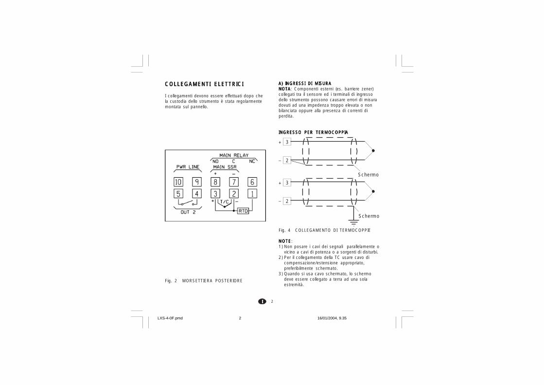
2IIIII
A) INGRESSI DI MISURAA) INGRESSI DI MISURAA) INGRESSI DI MISURAA) INGRESSI DI MISURAA) INGRESSI DI MISURANOTANOTANOTANOTANOTA: Componenti esterni (es. barriere zener)collegati tra il sensore ed i terminali di ingressodello strumento possono causare errori di misuradovuti ad una impedenza troppo elevata o nonbilanciata oppure alla presenza di correnti diperdita.
INGRESSO PER TERMOCOPPIAINGRESSO PER TERMOCOPPIAINGRESSO PER TERMOCOPPIAINGRESSO PER TERMOCOPPIAINGRESSO PER TERMOCOPPIA
Fig. 4 COLLEGAMENTO DI TERMOCOPPIE
NOTENOTENOTENOTENOTE:1) Non posare i cavi dei segnali parallelamente o
vicino a cavi di potenza o a sorgenti di disturbi.2) Per il collegamento della TC usare cavo di
compensazione/estensione appropriato,preferibilmente schermato.
3) Quando si usa cavo schermato, lo schermodeve essere collegato a terra ad una solaestremità.
COLLEGAMENTI ELETTRICICOLLEGAMENTI ELETTRICICOLLEGAMENTI ELETTRICICOLLEGAMENTI ELETTRICICOLLEGAMENTI ELETTRICI
I collegamenti devono essere effettuati dopo chela custodia dello strumento è stata regolarmentemontata sul pannello.
Fig. 2 MORSETTIERA POSTERIORE
3
2
+
_
3
2
+
_
Schermo
Schermo
LXS-4-0F.pmd 16/01/2004, 9.352

3IIIII
INGRESSO PER TERMORESISTENZAINGRESSO PER TERMORESISTENZAINGRESSO PER TERMORESISTENZAINGRESSO PER TERMORESISTENZAINGRESSO PER TERMORESISTENZA
Fig. 5 COLLEGAMENTO DITERMORESISTENZE
NOTENOTENOTENOTENOTE:1) Non posare i cavi dei segnali parallelamente o
vicino a cavi di potenza o a sorgenti di disturbi.2) Fare attenzione alla resistenza di linea, una
resistenza di linea eccessivamente alta(superiore a 20 Ω/filo) può causare errori dimisura.
3) Quando si usa cavo schermato, lo schermodeve essere collegato a terra ad una solaestremità.
4) I 3 fili devono avere la stessa impedenza.
1
RTD
32 1
RTD
32
USCITE A RELEUSCITE A RELEUSCITE A RELEUSCITE A RELEUSCITE A RELE
Fig. 6 USCITE A RELE'Il contatto NO dell'uscita 1 e il contatto dell'uscita 2sono protetti, tramite varistori, verso carichi cheabbiano componente induttiva fino a 0,5 A.La portata del contatto relativo all'uscita 1 è pari a3A/250V c.a. su carico resistivo.La portata del contatto relativo alle uscite 2 è paria 1A/250V c.a. su carico resistivo.Il numero delle operazioni è pari a 1 x 10⁵ allaportata specificata.NOTE:NOTE:NOTE:NOTE:NOTE:1)Per evitare scosse elettriche, collegare
l’alimentazione solo dopo aver terminato tutti glialtri collegamenti.
2) Per i collegamenti di potenza, utilizzare cavi No16 AWG o con sezione maggiore adatti ad unatemperatura di almeno 75 °C (167 °F).
3)Usare solo cavi di rame.4)Non posare cavi di segnale parallelamente o
vicino a cavi di potenza.
Le raccomandazioni che seguono possonoevitare seri problemi causati dal utilizzo delleuscite a relè per pilotare carichi induttivi
8
6
7C
NC
NO
OUT 1
4
5C
NO
OUT 2
LXS-4-0F.pmd 16/01/2004, 9.353

4IIIII
USCITA LOGICA PER IL COMANDO DI SSRUSCITA LOGICA PER IL COMANDO DI SSRUSCITA LOGICA PER IL COMANDO DI SSRUSCITA LOGICA PER IL COMANDO DI SSRUSCITA LOGICA PER IL COMANDO DI SSR
Fig. 8 COLLEGAMENTO PER IL PILOTAGGIODI RELE A STATO SOLIDO.
Questa è una uscita a tempo proporzionale.Livello logico 0Livello logico 0Livello logico 0Livello logico 0Livello logico 0: Vout < 0.5 V c.c.Livello logico 1Livello logico 1Livello logico 1Livello logico 1Livello logico 1: Corrente massima = 20 mA.- 14 V + 20 % @ 20 mA- 24 V + 20 % @ 1 mA.NOTENOTENOTENOTENOTE: Questa uscita NON è isolata.Un isolamento doppio o rinforzato tra lostrumento e la linea di potenza deve essereassicurato dal relè a stato solido esterno.
D) ALIMENTAZIONED) ALIMENTAZIONED) ALIMENTAZIONED) ALIMENTAZIONED) ALIMENTAZIONE
Fig. 3 COLLEGAMENTO ALL'ALIMENTAZIONE
+
_ _+
8
7
OUT 1
RELE A STATOSOLIDO
CARICHI INDUTTIVICARICHI INDUTTIVICARICHI INDUTTIVICARICHI INDUTTIVICARICHI INDUTTIVI
Nella commutazione di carichi induttivi si possonogenerare transitori e disturbi che possono pregiudi-care le prestazioni dello strumento.Le protezioni interne (varistori) assicurano laprotezione dai disturbi per carichi aventi unacomponente induttiva fino a 0,5 A.Problemi analoghi possono essere generati dallacommutazione di carichi tramite un contattoesterno in serie al contatto di uscita dellostrumento oppure dall'utilizzo del contatto NCdell'uscita 1.
Fig. 7 CONTATTO ESTERNO IN SERIE ALCONTATTO DI USCITA DELLO STRUMENTO
In questi casi si raccomanda di collegare un filtroRC in parallelo al contatto esterno come indicatoin fig. 7.
Il valore della capacità (C) e del resistore (R)sono indicati nella tabella seguente.
In tutti i casi i cavi collegati con le uscite a relèdevono rimanere il più lontano possibile dai cavidei segnali.
CARICO(mA)
<40 mA<150 mA<0.5 A
C(mF)
0.0470.10.33
R(W)
1002247
P.(W)
1/222
Tensione dilavoro
260 V AC260 V AC260 V AC
9
R (
S,T
)R (S,T)
N
10N
Rete da 100 V a 240 V c.a. (50/60Hz)
oppure 24 V c.c./c.a.
C R
LOAD
POWERLINE
LXS-4-0F.pmd 16/01/2004, 9.354

5IIIII
IMPOSTAZIONI HARDWAREIMPOSTAZIONI HARDWAREIMPOSTAZIONI HARDWAREIMPOSTAZIONI HARDWAREIMPOSTAZIONI HARDWAREPRELIMINARIPRELIMINARIPRELIMINARIPRELIMINARIPRELIMINARI1) Estrarre lo strumento dalla custodia.2) Posizionare lo switch V2 in posizione aperta.
3) Questi strumenti sono ingrado di rilevare l’apertura delcircuito di ingresso (TC o RTD)che viene visualizzato comeuna condizione di overrange.Per le sole termocoppie èpossibile selezionare, tramite ijumpers SH401 e CH401indicati nella figura a lato, iltipo di indicazione che sidesidera ottenere in caso ditermocoppia aperta.
SH401 CH401 Indicazione
aperto chiuso overrange (Standard)
chiuso aperto underrange
NOTENOTENOTENOTENOTE:1) Prima di collegare lo strumento alla rete,
assicurarsi che la tensione di linea siacorrispondente a quanto indicato nella targa diidentificazione dello strumento.
2) Per evitare il rischio di scosse elettriche collegarel'alimentazione solo dopo aver effettuato tutti glialtri collegamenti.
3) Per il collegamento alla rete, utilizzare cavi No 16AWG o maggiori adatti per una temperatura dialmeno 75 °C.
4) Utilizzare solo conduttori di rame.5) Non posare i cavi dei segnali parallelamente o
vicino a cavi di potenza o a sorgenti di disturbi.6) Per l'alimentazione 24 V c.c./c.a. la polarità non
ha importanza.7) I circuiti di alimentazione NON sono protetti da
fusibile, pertanto si consiglia di prevederne unoesterno con le seguenti caratteristiche:Fusibile tipo T, 1 A, 250 V.
8) Le normative sulla sicurezza relative adapparecchiature collegate permanentementeall'alimentazione richiedono:- un interruttore o disgiuntore va compreso
nell'impianto elettrico dell'edificio;- esso deve trovarsi in stretta vicinanza
dell'apparecchio ed essere facilmenteraggiungibile da parte dell'operatore;
- deve essere marcato come il dispositivo diinterruzione dell'apparecchio.
NOTANOTANOTANOTANOTA: un singolo interruttore o disgiuntore puòcomandare più apparecchi.
V2
SH401CH401
Fig. 9
LXS-4-0F.pmd 16/01/2004, 9.355

6IIIII
PROCEDURE DI CONFIGURAZIONEPROCEDURE DI CONFIGURAZIONEPROCEDURE DI CONFIGURAZIONEPROCEDURE DI CONFIGURAZIONEPROCEDURE DI CONFIGURAZIONE
P1 - Tipo di ingresso e scala standardP1 - Tipo di ingresso e scala standardP1 - Tipo di ingresso e scala standardP1 - Tipo di ingresso e scala standardP1 - Tipo di ingresso e scala standard0 = TC tipo L scala 0 / +800 °C1 = TC tipo J scala 0 / +800 °C2 = TC tipo K scala 0 / +999 °C3 = TC tipo N scala 0 / +999 °C4 = RTD tipo Pt 100 scala -199 / +500 °C5 = RTD tipo Pt 100 scala -19.9 / +99.9 °C6 = TC tipo T scala 0 / +400 °C8 = TC tipo L scala 0 / +999 °F9 = TC tipo J scala 0 / +999 °F10 = TC tipo K scala 0 / +999 °F11 = TC tipo N scala 0 / +999 °F12 = RTD tipo Pt 100 scala -199 / +999 °F13 = TC tipo T scala 0 / +752 °FNOTANOTANOTANOTANOTA: Per i campi di misura in °F, è disponibileuna etichetta adesiva indicante °F da incollare sulfrontale dello strumento.Detta etichetta, riportata sopra “INDICE ” diquesto manuale, deve essere collocata sopral’indicazione °C.
P2 = Inizio scalaP2 = Inizio scalaP2 = Inizio scalaP2 = Inizio scalaP2 = Inizio scalaNon disponibile se P1 = 5Valore di inizio scala utilizzato dall’algoritmo PIDper i calcoli dell’ampiezza del campo di lavoro.
P3 = Fondo scalaP3 = Fondo scalaP3 = Fondo scalaP3 = Fondo scalaP3 = Fondo scalaNon disponibile se P1 = 5Valore di fondo scala utilizzato dall’algoritmo PID.NOTENOTENOTENOTENOTE:1) l’ampiezza del campo di lavoro impostato (P3 -
P2) deve essere superiore a 300 °C o 600 °Fper ingresso da termocoppia; 100 °C o 200 °Fper ingresso da termoresistenza.
2) Se si modifica il valore di P3 e/o P4, i parametrirL ed rH verranno automaticamente allineatirispettivamente al nuovo valore di P3 e P4.
4) Se lo strumento è stato programmato per lavisualizzazione in °F, applicare l’etichettaaddizionale, situata sulla pagina dell'INDICE,sul frontale dello strumento in modo da coprirel’attuale unità ingegneristica (°C).
5) Reinserire lo strumento.6) Alimentare lo strumento.
Lo strumento indicherà “CnF”.ATTENZIONEATTENZIONEATTENZIONEATTENZIONEATTENZIONE: Se lo strumento dovessevisualizzare l’indicazione “CAL” premereimmediatamente il tasto per tornare allafase di configurazione.
7) Premere il tasto FN.Per LMS-LHS, il display inferiore visualizzeràil codice del parametro selezionato mentre ildisplay superiore ne visualizzeràl’impostazione.Per LDS il codice del parametro ed il relativovalore verranno visualizzati alternativamente.
NOTE GENERALI di configurazione.NOTE GENERALI di configurazione.NOTE GENERALI di configurazione.NOTE GENERALI di configurazione.NOTE GENERALI di configurazione.FN = Consente di memorizzare il nuovo
valore del parametro selezionato epassare al parametro successivo(ordine crescente).
ST = Consente di visualizzare i parametri inordine decrescente senza memorizza-re i nuovi valori.
= Consente di aumentare il valore delparametro selezionato.
= Consente di diminuire il valore delparametro selezionato.
°F°F°F°F°F
LXS-4-0F.pmd 16/01/2004, 9.356
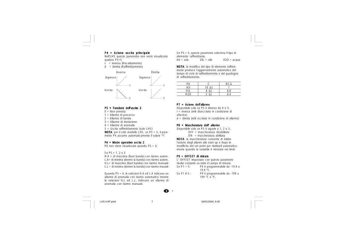
7IIIII
P4 = Azione uscita principaleP4 = Azione uscita principaleP4 = Azione uscita principaleP4 = Azione uscita principaleP4 = Azione uscita principaleNell’LHS questo parametro non verrà visualizzatoqualora P5=5r = inversa (Riscaldamento)d = diretta (Raffreddamento)
P5 = Funzione dell’uscita 2P5 = Funzione dell’uscita 2P5 = Funzione dell’uscita 2P5 = Funzione dell’uscita 2P5 = Funzione dell’uscita 20 = Non prevista1 = Allarme di processo2 = Allarme di banda3 = Allarme di deviazione4 = Allarme di anomalia5 = Uscita raffreddamento (solo LHS)NOTANOTANOTANOTANOTA: per il solo modello LHS, se P5 = 5, il para-metro P4 assume automaticamente il valore “r”.
P6 = Modo operativo uscita 2P6 = Modo operativo uscita 2P6 = Modo operativo uscita 2P6 = Modo operativo uscita 2P6 = Modo operativo uscita 2P6 non viene visualizzato quando P5 = 0.
Se P5 = 1, 2 o 3H.A = di massima (fuori banda) con riarmo autom.L.A= di minima (dentro la banda) con riarmo autom.H.L= di massima (fuori banda) con riarmo manualeL.L = di minima (dentro la banda) con riarmo mauale
Quando P5 = 4, le selezioni H.A ed L.A indicano unallarme di anomalia con riarmo automatico mentrele selezioni H.L ed L.L. indicano un allarme dianomalia con riarmo manuale.
t
Ingresso
t
Uscita
t
Ingresso
t
Uscita
Inversa Diretta
Se P5 = 5, questo parametro seleziona il tipo dielemento raffreddante.AIr = aria OIL = olio H2O = acqua
NOTANOTANOTANOTANOTA: la modifica del tipo di elemento raffred-dante produce l’aggiornamento automatico deltempo di ciclo di raffreddamento e del guadagnodi raffreddamento.
P6 C RCGAIr 10 (s) 1OIL 4 (s) 0.8H2O 2 (s) 0.4
P7 = Azione dell’allarmeP7 = Azione dell’allarmeP7 = Azione dell’allarmeP7 = Azione dell’allarmeP7 = Azione dell’allarmeDisponibile solo se P5 è diverso da 0 o 5.r = inversa (relè diseccitato in condizione diallarme)d = diretta (relè eccitato in condizione di allarme)
P8 = Mascheratura dell’ allarmeP8 = Mascheratura dell’ allarmeP8 = Mascheratura dell’ allarmeP8 = Mascheratura dell’ allarmeP8 = Mascheratura dell’ allarmeDisponibile solo se P5 è uguale a 1, 2 o 3.
OFF = mascheratura disabilitataON = mascheratura abilitata
NOTANOTANOTANOTANOTA: la mascheratura consente di inibirel’azione degli allarmi allo start up e dopo lemodifiche del set point per riattivarli automatica-mente quando la variabile è rientrata nei limiti.
P9 = OFFSET di misuraP9 = OFFSET di misuraP9 = OFFSET di misuraP9 = OFFSET di misuraP9 = OFFSET di misuraL’ OFFSET impostato con questo parametrorisulta costante su tutto il campo di misura.Se P1 = 5: P9 è programmabile da -19.9 a
19.9 °C.Se P1 # 5 : P9 è programmabile da -199 a
199 °C o °F.
LXS-4-0F.pmd 16/01/2004, 9.357
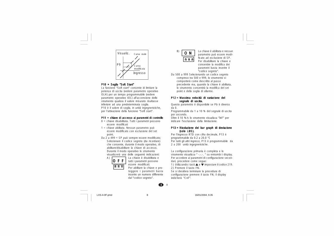
8IIIII
P10 = Soglia “Soft Start”P10 = Soglia “Soft Start”P10 = Soglia “Soft Start”P10 = Soglia “Soft Start”P10 = Soglia “Soft Start”La funzione “Soft start” consente di limitare lapotenza di uscita (vedere parametro operativoOLH) per un tempo programmabile (vedereparametro operativo tOL) all’accensione dellostrumento qualora il valore misurato risultasseinferiore ad una predeterminata soglia.P10 è il valore di soglia, in unità ingegneristiche,per l’attivazione della funzione “Soft start”.
P11 = chiave di accesso ai parametri di controlloP11 = chiave di accesso ai parametri di controlloP11 = chiave di accesso ai parametri di controlloP11 = chiave di accesso ai parametri di controlloP11 = chiave di accesso ai parametri di controllo0 = chiave disabilitata. Tutti i parametri possono
essere modificati1 = chiave abilitata. Nessun parametro può
essere modificato con esclusione del setpoint.
Da 2 a 499 = SP può sempre essere modificato;Selezionare il codice segreto (da ricordare)che consente, durante il modo operativo, diabilitare/disabilitare la chiave di accesso.Durante il modo operativo lo strumentovisualizzerà una delle seguenti indicazioni:A ) La chiave è disabilitata e
tutti i parametri possonoessere modificati.Per abilitare la chiave e pro-teggere i parametri bastainserire un numero differentedal “codice segreto”.
B) La chiave è abilitata e nessunparametro può essere modi-ficato ad esclusione di SP.Per disabilitare la chiave econsentire la modifica deiparametri basta inserire il“codice segreto”.
Da 500 a 999 Selezionando un codice segretocompreso tra 500 e 999, lo strumento sicomporterà come descritto al passoprecedente ma, quando la chiave è abilitata,lo strumento consentirà la modifica del setpoint e della soglia di allarme.
P12 =P12 =P12 =P12 =P12 = Massima velocità di variazione delMassima velocità di variazione delMassima velocità di variazione delMassima velocità di variazione delMassima velocità di variazione delsegnale di uscita.segnale di uscita.segnale di uscita.segnale di uscita.segnale di uscita.
Questo parametro è disponibile se Pb è diversoda 0.Programmabile da 1 a 10 % del segnale di uscitaper secondo.Oltre il 10 %/s lo strumento visualizza “InF” perindicare l’esclusione della limitazione.
P13 =P13 =P13 =P13 =P13 = Risoluzione del bar graph di deviazioneRisoluzione del bar graph di deviazioneRisoluzione del bar graph di deviazioneRisoluzione del bar graph di deviazioneRisoluzione del bar graph di deviazione(solo LDS).(solo LDS).(solo LDS).(solo LDS).(solo LDS).
Per l'ingresso RTD con cifra decimale, P13 èprogrammabile da 0.2 a 20.0 °CPer tutti gli altri ingressi, P13 è programmabile da2 a 200 unità ingegneristiche.
La configurazione primaria è completa e lostrumento visualizza “ -.-.-. “ su entrambi i display.Per accedere ai parametri di configurazione secon-dari, procedere come segue:1) Utilizzando i tasti e impostare il codice 219.2) Premere il tasto FN.Se si desidera terminare la procedura diconfigurazione premere il tasto FN; il displayindicherà "CnF".
Curva realeVisualiz.
Curvamodificata
Ingresso
P9
O F FO F FO F FO F FO F Fn n nn n nn n nn n nn n n
O NO NO NO NO N
n n nn n nn n nn n nn n n
LXS-4-0F.pmd 16/01/2004, 9.358
9IIIII
P14 -P14 -P14 -P14 -P14 - Abil i tazione/disabil i tazione dellaAbil i tazione/disabil i tazione dellaAbil i tazione/disabil i tazione dellaAbil i tazione/disabil i tazione dellaAbil i tazione/disabil i tazione dellavisualizzazione dei parametri protetti.visualizzazione dei parametri protetti.visualizzazione dei parametri protetti.visualizzazione dei parametri protetti.visualizzazione dei parametri protetti.
Questo parametro è disponibile se P 11 è diversoda 0.Questo parametro consente di abilitare odisabilitare, durante il modo operativo, lavisualizzazione dei parametri protetti.OFF = I parametri protetti non possono esserevisualizzatiON = I parametri protetti possono esserevisualizzati.
P15 - Abilitazione/disabilitazione dellaP15 - Abilitazione/disabilitazione dellaP15 - Abilitazione/disabilitazione dellaP15 - Abilitazione/disabilitazione dellaP15 - Abilitazione/disabilitazione dellafunzione SMARTfunzione SMARTfunzione SMARTfunzione SMARTfunzione SMART
0 = La funzione SMART èdisabilitata
1 = L'abilitazione/disabilitazionedella funzione SMART NON NON NON NON NON èprotetta dal codice di sicurezza.
2 = L'abilitazione/disabilitazionedella funzione SMART èprotetta dal codice di sicurezza.
P16 -P16 -P16 -P16 -P16 - Valore massimo di banda proporzionaleValore massimo di banda proporzionaleValore massimo di banda proporzionaleValore massimo di banda proporzionaleValore massimo di banda proporzionaleimpostabile automaticamente dallaimpostabile automaticamente dallaimpostabile automaticamente dallaimpostabile automaticamente dallaimpostabile automaticamente dallafunzione SMART.funzione SMART.funzione SMART.funzione SMART.funzione SMART.
Questo parametro può assumere i valori compresitra P17 o P18 e 99.9.
P17 -P17 -P17 -P17 -P17 - Valore minimo di banda proporzionale Valore minimo di banda proporzionale Valore minimo di banda proporzionale Valore minimo di banda proporzionale Valore minimo di banda proporzionaleimpostabile automaticamente dallaimpostabile automaticamente dallaimpostabile automaticamente dallaimpostabile automaticamente dallaimpostabile automaticamente dallafunzione SMART per strumenti con unafunzione SMART per strumenti con unafunzione SMART per strumenti con unafunzione SMART per strumenti con unafunzione SMART per strumenti con unasola uscita regolante.sola uscita regolante.sola uscita regolante.sola uscita regolante.sola uscita regolante.
Questo parametro viene visualizzato solo se P5 èdiverso da 5.P17 può assumere i valori compresi tra 1.0% edil valore di P16.
P18 -P18 -P18 -P18 -P18 - Valore minimo di banda propor- Valore minimo di banda propor- Valore minimo di banda propor- Valore minimo di banda propor- Valore minimo di banda propor-zionale impostabile automaticamen-zionale impostabile automaticamen-zionale impostabile automaticamen-zionale impostabile automaticamen-zionale impostabile automaticamen-te dalla funzione SMART perte dalla funzione SMART perte dalla funzione SMART perte dalla funzione SMART perte dalla funzione SMART perstrumenti con due uscite regolantistrumenti con due uscite regolantistrumenti con due uscite regolantistrumenti con due uscite regolantistrumenti con due uscite regolanti(LHS) .(LHS) .(LHS) .(LHS) .(LHS) .
Questo parametro viene visualizzato solo se P5 èuguale a 5.P18 può assumere i valori compresi tra 1.5% edil valore di P16.
P19 -P19 -P19 -P19 -P19 - Calcolo automatico del "guadagnoCalcolo automatico del "guadagnoCalcolo automatico del "guadagnoCalcolo automatico del "guadagnoCalcolo automatico del "guadagnorelativo di raffreddamento" (LHS).relativo di raffreddamento" (LHS).relativo di raffreddamento" (LHS).relativo di raffreddamento" (LHS).relativo di raffreddamento" (LHS).
Questo parametro è presente solo se P5 è ugualea 5.
OFF = La funzione SMART NONNONNONNONNONcalcola il guadagno relativo diraffreddamento.
ON = La funzione SMART calcola ilguadagno relativo di raffredda-mento.
P20 - Minimo valore di tempo integraleP20 - Minimo valore di tempo integraleP20 - Minimo valore di tempo integraleP20 - Minimo valore di tempo integraleP20 - Minimo valore di tempo integralecalcolato dalla funzione SMART.calcolato dalla funzione SMART.calcolato dalla funzione SMART.calcolato dalla funzione SMART.calcolato dalla funzione SMART.
P20 puo assumere valori compresi tra 00.1 (10secondi) e 02.0 (2 minuti).
P21 = Estensione dell'anti-reset-wind upP21 = Estensione dell'anti-reset-wind upP21 = Estensione dell'anti-reset-wind upP21 = Estensione dell'anti-reset-wind upP21 = Estensione dell'anti-reset-wind upCampo: da -30 a +30 % della banda proporziona-le.NOTANOTANOTANOTANOTA: un valore positivo aumenta il limitemassimo della funzione (sopra il set point) mentreun valore negativo abbassa il limite minimo dellafunzione (sotto il set point).
Anche le procedure di configurazione avanzatasono terminate e lo strumento visualizzerà "CnF".
LXS-4-0F.pmd 16/01/2004, 9.359

10IIIII
MODO OPERATIVOMODO OPERATIVOMODO OPERATIVOMODO OPERATIVOMODO OPERATIVO
PRELIMINARIPRELIMINARIPRELIMINARIPRELIMINARIPRELIMINARIPer rendere operativo lo strumento in modoregolazione, è necessario che il ponticello V2(vedere fig. 9) risulti chiuso.
Si assume che lo strumento sia stato configuratocorrettamente secondo le indicazioni riportatenella sezione 3.
- I modelli LMS ed LHS visualizzano sul displaysuperiore il valore misurato mentre il displayinferiore viene utilizzato normalmente per visua-lizzare il set point operativo (noi definiremo questacondizione come "Visualizzazione normale").
- Il modello LDS visualizza il valore misurato (noidefiniremo questa condizione come "Visualizza-zione normale") o il set point operativo (nel secondocaso il LED SP lampeggerà). Per passare dallavisualizzazione del set point a quella del valoremisurato o viceversa, premere il tasto .
Premendo il tasto FN è possibile visualizzaresequenzialmente tutti i parametri.- I modelli LMS ed LHS visualizzano sul display
inferiore il nome abbreviato del parametroselezionato mentre sul display superiore ilvalore impostato.
- Il modello LDS visualizza alternatamente il nomedel parametro ed il suo valore mentre, durante lamodifica, visualizza il solo valore del parametro.
Per modificare l'impostazione di un parametroprocedere come segue:1) Selezionare, tramite il tasto FN, il parametroche si desidera modificare.2) Utilizzando i tasti e impostare il valoredesiderato.
3) Premere il tasto FN per memorizzare il nuovovalore e passare al parametro successivo.NOTENOTENOTENOTENOTE:1) Se, durante la modifica di un parametro, non
viene premuto alcun pulsante per un periodosuperiore a 10 secondi, lo strumento ritornaautomaticamente alla visualizzazionenormale mentre la nuova impostazionedell'ultimo parametro verrà persa.
2) Lo strumento non visualizza tutti i possibiliparametri ma visualizza solo i parametri cherisultano in accordo con:a )La configurazione dello strumento (vedere
sezione 3),b) l'impostazione del parametro P14 (vedere
sezione 3),c) L'impostazione della banda proporzionale
(vedere pagina seguente).
INDICATORIINDICATORIINDICATORIINDICATORIINDICATORIST Lampeggia quando la funzione SMART ese-
gue la prima fase di autosintonizzazione.Acceso quando la funzione SMART eseguela seconda fase di autosintonizzazione
OUT acceso quando l'uscita 1 è in condizioneON.
ALM/COOL acceso quando l'uscita 2 è incondizione ON o l'allarme 1 è in condizio-ne di allarme.
SP (solo LDS) lampeggia quando lostrumento visualizza il set point diregolazione.
LXS-4-0F.pmd 16/01/2004, 9.3510

11IIIII
Descrizione della tastieraDescrizione della tastieraDescrizione della tastieraDescrizione della tastieraDescrizione della tastieraFN = consente di memorizzare la nuova
impostazione del parametro e passare alparametro successivo (ordine crescente).
ST = consente di attivare/disattivare la funzioneSMART o di scorrere i parametri in ordineinverso senza memorizzarne i valori.
= incrementa il valore del parametrovisualizzato oppure, per il solo LDS,consente di visualizzare il valore del setpoint di regolazione.
= decrementa il valore del parametrovisualizzato.
+ FN = abilita/disabilita il LAMP TEST.
NOTANOTANOTANOTANOTA: la modifica dei parametri operativi è sottopo-sta ad un time out di 10 secondi. Se, durante lamodifica dei parametri non viene eseguita alcunaoperazione sui tasti per un periodo superiore a 10secondi, lo strumento ritorna alla visualizzazionenormale memorizzando solo le modifiche dei para-metri che sono state seguite dalla pressione deltasto FN.
RIARMO MANUALE DELL'ALLARME.RIARMO MANUALE DELL'ALLARME.RIARMO MANUALE DELL'ALLARME.RIARMO MANUALE DELL'ALLARME.RIARMO MANUALE DELL'ALLARME.Se è stato selezionato un allarme con riarmomanuale, la segnalazione di allarme persisteràanche dopo che la condizione di allarme èscomparsa.Per riarmare l'allarme, premendo il tasto FNselezionare il parametro "n.rS" (il visualizzatoreindicherà "n.rS" e "OFF"). Tramite i tasti e selezionare "ON" e premere il tasto FN.Il riarmo manuale dell'allarme andrà a buon finesolo se la condizione di allarme non è piùpresente.
ALGORITMO SMARTALGORITMO SMARTALGORITMO SMARTALGORITMO SMARTALGORITMO SMARTQuesta funzione consente il controllo ottimale delprocesso.Per abilitare questa funzione è sufficiente premereper oltre 1.5 secondi il tasto ST durante la “visualiz-zazione normale”; il LED “ST” risulterà acceso fissoo lampeggiante in funzione dell’algoritmo selezio-nato dallo strumento. Quando la funzione SMART èabilitata, lo strumento concede di visualizzare iparametri di regolazione tradizionali (PB, TI, TD erC) senza però consentirne la modifica.Qualora si desiderasse tornare al controllotradizionale (PID) basta premere nuovamente iltasto ST per almeno 1,5 secondi. Lo strumentomanterrà l’attuale impostazione dei parametri dicontrollo e ne abiliterà la modifica.NOTE NOTE NOTE NOTE NOTE :1) Quando la funzione SMART è operativa, il
guadagno relativo di raffreddamento (secontrollato dalla funzione SMART) vienelimitato come segue:
Elemento raffreddante CampoAir 0.85 a 1.00OIL 0.80 a 0.90H2O 0.30 a 0.60
2) La funzione SMART utilizza un tempodell'azione derivativa uguale ad un quarto deltempo dell'azione integrale.
3) I limiti dell'azione proporzionale sono program-mabili tramite i parametri P16, P17 e P18.
4) Quando la funzione SMART è attiva, il minimovalore dell'azione integrale è definito dalparametro P20
5) programmando lo strumento per la regolazionedi tipo ON/OFF (Pb=0) la funzione SMARTviene automaticamente inibita.
6) L’abilitazione/disabilitazione della funzioneSMART puo essere protetta dalla chiave diaccesso ai parametri (fare riferimento alparametro P15).
LXS-4-0F.pmd 16/01/2004, 9.3511

12IIIII
MODIFICA DIRETTA DEL SET POINTMODIFICA DIRETTA DEL SET POINTMODIFICA DIRETTA DEL SET POINTMODIFICA DIRETTA DEL SET POINTMODIFICA DIRETTA DEL SET POINTQuesti strumenti consentono di modificare il setpoint senza utilizzare il tasto FN.Quando si desidera modificare rapidamente il setpoint, procedere come segue:1) Premere, per più di 3 secondi, il tasto o , il
valore del set point comincerà a cambiare.2) Tramite i tasti e , impostare il valore
desiderato.3) Una volta raggiunto il valore desiderato, NON
premere alcun tasto; il nuovo valore di setpoint diventerà operativo 3 secondi dopol’ultima pressione dei tasti e lo strumentotornerà alla “visualizzazione normale”.
Se durante questa procedura si desidera perderela modifica, premere il tasto FN; lo strumentotorna automaticamente alla “visualizzazionenormale” senza memorizzare il nuovo set point.
VISUALIZZAZIONE DEL SET POINT VISUALIZZAZIONE DEL SET POINT VISUALIZZAZIONE DEL SET POINT VISUALIZZAZIONE DEL SET POINT VISUALIZZAZIONE DEL SET POINT IMPOSTA-IMPOSTA-IMPOSTA-IMPOSTA-IMPOSTA-TO (solo LDS)TO (solo LDS)TO (solo LDS)TO (solo LDS)TO (solo LDS)Per visualizzare sul display il set point impostatobasta premere il tasto .Sul display apparirà il valore di set point seguitodal lampeggio del punto decimale relativo allacifra meno significativa (indicata sul frontale dallascritta SP).Per tornare alla visualizzazione del valoremisurato basta premere nuovamente il tasto .
INIBIZIONE DEL SEGNALE DI USCITAINIBIZIONE DEL SEGNALE DI USCITAINIBIZIONE DEL SEGNALE DI USCITAINIBIZIONE DEL SEGNALE DI USCITAINIBIZIONE DEL SEGNALE DI USCITAQuesti strumenti consentono di inibire manualmen-te il segnale di uscita onde poter bloccare laregolazione.Per inibire il segnale di uscita premere il tasto e, mantenendolo premuto, premere il tasto FNper almeno 3 secondi.Lo strumento visualizzerà la scritta “OFF” al postodell’indicazione di set point; il segnale di uscitaandrà in OFF e lo strumento funzionerà dasemplice indicatore.Per il solo modello LDS, premendo il tasto saràpossibile visualizzare il valore misurato ma i treLED del bar graph risulteranno lampeggianti (perindicare che lo strumento sta operando comesemplice indicatore).Quando le uscite regolanti sono disabilitate anchegli allarmi risultano disabilitati e forzati allacondizione di assenza di allarme.Resta comunque abilitata la modifica deiparametri di regolazione.Per tornare al funzionamento come regolatorepremere il tasto e, mantenendolo premuto,premere il tasto FN per almeno 3 secondi.NOTENOTENOTENOTENOTE:1) Se l'uscita viene inibita quando la funzione SMART
sta eseguendo la prima parte dell'algoritmo diauto-sintonizzazione (LED ST lampeggiante),quando lo strumento tornerà al normale control-lo, la funzione risulterà disabilitata.Se l'uscita viene inibita quando la funzioneSMART sta eseguendo la normale operatività(LED ST acceso), la funzione SMART verràtemporaneamente bloccata; quando lostrumento tornerà al normale controllo, lafunzione risulterà nuovamente attiva.
2) Se lo strumento viene spento quando la funzionedi inibizione del segnale di uscita è attiva, allasuccessiva riaccensione detta funzione verràriattivata automaticamente.
LXS-4-0F.pmd 16/01/2004, 9.3512

13IIIII
FUNZIONALITÀ DEL BAR GRAPH (SOLOFUNZIONALITÀ DEL BAR GRAPH (SOLOFUNZIONALITÀ DEL BAR GRAPH (SOLOFUNZIONALITÀ DEL BAR GRAPH (SOLOFUNZIONALITÀ DEL BAR GRAPH (SOLOLDS)LDS)LDS)LDS)LDS)Il bar graph a 3 LED indica la deviazione esistentetra la misura ed il set point impostato.Il LED centrale (verde) è acceso quando ladeviazione è inferiore alla metà del valoreimpostato tramite il parametro P13Se la deviazione è superiore ad 1/2 P13 ma inferioreai 3/2 P13 il relativo LED rosso risulterà acceso.Qualora la deviazione risultasse superiore ai 3/2del valore di P13, il relativo LED risulteràlampeggiante.
LAMP TESTLAMP TESTLAMP TESTLAMP TESTLAMP TESTQuando si desidera verificare il funzionamentodel visualizzatore , premere i tasti e FN. Lostrumento accenderà tutti i LED del visualizzatorecon un duty cicle pari al 50 % (questo stato verràchiamato LAMP TEST).Il LAMP TEST non è sottoposto a time out.quando si desidera tornare al modo normale divisualizzazione, premere nuovamente i tasti eFN.Durante il LAMP TEST non sono disponibili altrefunzioni.
PARAMETRI OPERATIVIPARAMETRI OPERATIVIPARAMETRI OPERATIVIPARAMETRI OPERATIVIPARAMETRI OPERATIVISegue la lista completa dei parametri di controllo.Si noti che alcuni parametri potrebbero non venirvisualizzati in funzione della configurazionespecifica dell'apparecchio.
Premere il tasto FUNC, il display inferiorevisualizzerà il codice mentre quello superiorevisualizzerà il valore del parametro selezionato.Tramite i tasti e è possibile impostare il valoreo lo stato desiderato.Premendo il tasto FUNC lo strumento memorizzeràil nuovo valore (o il nuovo stato) e passerà allavisualizzazione del parametro successivo.
Param.DescrizioneSP Set point principale (in unità ing.)
Campo: da rL a rH.n.rS Riarmo manuale degli allarmi
Questo parametro viene visualizzato sealmeno un allarme è programmato con ilriarmo manuale.Impostare ON e premere FN per riarmaregli allarmi.
nnn Chiave di protezione dei parametri.Non viene visualizzato se P11 = 0 o 1.ON= La protezione dei parametri è attiva.OFF= La protezione dei parametri è inattiva.Quando si desidera disattivare la protezionedei parametri, impostare un valore uguale alvalore assegnato al parametro P11.Quando si desidera riattivare la protezionedei parametri, impostare un valore differentedal valore assegnato al parametro P11.
AL Soglia Allarme (in unità ing.)AL1 viene visualizzato solo se l'allarme èstato configurato.
LXS-4-0F.pmd 16/01/2004, 9.3513

14IIIII
Campi:- all'interno del campo di ingresso (P3 - P2)per allarme di processo.- da 0 a 500 unità per allarme di banda.- da -199 a 500 unità per allarme dideviazione.
HSA Isteresi allarme (in % del campo P3 - P2)HSA viene visualizzato solo se l'allarme èstato configurato.Campo: da 0.1% a 10.0% del campo diingresso oppure 1 LSDNotaNotaNotaNotaNota: Se l'isteresi di un allarme di bandarisultasse piu ampia della bandadell'allarme stesso, lo strumento utilizzeràun valore di isteresi pari al valore di bandaprogrammato meno un digit.
Pb Banda proporzionale (in % del campo P3 -P2)Campo: da 1.0% a 99.9 % dell'ampiezzadel campo di ingresso con una uscitaregolante.Da 1.5% a 99.9 % dell'ampiezza delcampo di ingresso con due usciteregolanti (solo LHS).Quando Pb = 0 l'azione regolante diventadi tipo ON/OFF; i parametri ti, td, IP, C,C2, rC, OLP, OLH e tOL non verrannovisualizzati mentre la funzione SMARTrisulterà non abilitabile.
HS Isteresi per regolazione ON/OFF (in % delcampo P3 - P2)HS è disponibile solo se Pb =0.Campo: da 0.1% a 10.0% dell'ampiezzadel campo di ingresso.
ti Tempo integrale (in minuti e secondi[mm.ss]). "ti" non viene visualizzatoquando Pb=0 (azione ON/OFF).Campo : da 00.1 a 20.0 mm.ssOltre questo valore il display si oscura e
l'azione integrale risulta esclusa.td Tempo derivativa (in minuti e secondi
[mm.ss]). "td" non viene visualizzatoquando Pb=0 (azione ON/OFF).Campo: da 0.01 a 9.59 mm.ss. Impostan-do il valore 0 l'azione derivativa risulteràesclusa.
IP Precarica dell'azione integrale. Ip èdisponibile solo se Pb è diverso da 0.Campo:- da 0 a 100 % per una azione regolante- da -100 a 100 % per due azioni regolanti(solo LHS).
C Tempo di ciclo uscita 1 (in secondi). C èdisponibile solo se Pb è diverso da 0.Campo: da 1 a 200 s.
C2 Tempo di ciclo uscita 2 (in secondi) (soloLHS). C2 è disponibile solo se P5 èdiverso da 0.Campo: da 1 a 200 s.
rC Guadagno relativo di raffreddamento."rC" non viene visualizzato se Pb=0(azione ON/OFF) o l'apparecchio èconfigurato per una uscita regolante.Campo: da 0.20 a 1.00.
OLP Sovrapposizione/banda morta trariscaldamento e raffreddamento (in %della banda proporzionale)."OLP" non viene visualizzato se Pb=0(azione ON/OFF) o l'apparecchio èconfigurato per una uscita regolante.Un valore negativo indica una bandamorta mentre un valore positivo indica unasovrapposizione.Campo: da -20% a 50%.
rL Limite inferiore del set point (in unità ing.)Campo: dal valore di inizio scala (P2) a rH.NotaNotaNotaNotaNota: se P2 viene modificato, anche rLviene riallineato automaticamente.
LXS-4-0F.pmd 16/01/2004, 9.3514

15IIIII
rH Limite superiore del set point (in unità ing.)Campo: da rL al valore di fondo scala(P3).NotaNotaNotaNotaNota: se P3 viene modificato, anche rHviene riallineato automaticamente.
OLH Limite massimo dell'uscita regolante (in %dell'uscita)Campo:- da 0.0 a 100.0 quando lo strumento èprogrammato per una sola uscita regolante.- da -100.0 a 100.0 quando lo strumento èprogrammato per due uscite regolanti(solo LHS).
tOL Durata della limitazione della potenza diuscita (in minuti).All'accensione lo strumento misura la varia-bile di processo, confronta il valore misuratocon la soglia programmata per la funzionesoft start (parametro P10 della sezione 3) e,se la variabile misurata è inferiore alla so-glia, limita la potenza di uscita al valore OLH.Da questo momento inizia il conteggio deltempo. Il parametro tOL consente di definirela durata, in minuti, di questa limitazione.Allo scadere del tempo tOL, lo strumentotoglie la limitazione e la potenza di uscitapotrà assumere quindi un valore qualsiasi.Questo parametro viene visualizzato soloquando la banda proporzionale è diversada zero.Campo: da 1 a 100 min. Oltre questovalore il display indica “Inf” e la limitazionerisulterà sempre inserita.NotaNotaNotaNotaNota: il parametro tOL può essere modifica-to in qualsiasi momento ma il nuovo valorediventerà operativo solo alla successiva ac-censione dello strumento.
MESSAGGI DI ERROREMESSAGGI DI ERROREMESSAGGI DI ERROREMESSAGGI DI ERROREMESSAGGI DI ERRORE
SEGNALAZIONE ANOMALIA DELLASEGNALAZIONE ANOMALIA DELLASEGNALAZIONE ANOMALIA DELLASEGNALAZIONE ANOMALIA DELLASEGNALAZIONE ANOMALIA DELLAMISURAMISURAMISURAMISURAMISURALo strumento visualizzerà il rilevamento di unacondizione di OVERRANGE ed UNDERRANGEvisualizzando sul display superiore una delleseguenti indicazioni:
OVER RANGE UNDER RANGE
La rottura del sensore viene segnalata comesegue:- ingresso TC/mV: OVERRANGE o
UNDERRANGE seleziona-bile tramite ponticello
- ingresso RTD: OVERRANGE
Per l'ingresso RTD, lo strumento segnala unacondizione di OVERRANGE quando la resistenzadi ingresso risulta inferiore a 15 ohm (rilevazionedel cortocircuito del sensore).
NOTANOTANOTANOTANOTA: quando:- lo strumento è programmato per utilizzare una
sola uscita regolante ed ha rilevato unacondizione di OVERRANGE, l'uscita 1 vieneforzata a zero (per azione inversa) oppure a100% (per azione diretta).
- lo strumento è programmato per utilizzare dueuscite regolanti ed ha rilevato una condizione diOVERRANGE, l'uscita 1 viene forzata a zeromentre l'uscita 2 viene forzata a 100%.
- lo strumento è programmato per utilizzare una
LXS-4-0F.pmd 16/01/2004, 9.3515

16IIIII
sola uscita regolante ed ha rilevato unacondizione di UNDERRANGE, l'uscita 1 vieneforzata a 100% (per azione inversa) oppure a zero(per azione diretta).
- lo strumento è programmato per utilizzare dueuscite regolanti ed ha rilevato una condizione diUNDERRANGE, l'uscita 1 viene forzata a 100%mentre l'uscita 2 viene forzata a zero.
Per gli ingressi da termocoppia è possibileselezionare l'indicazione di underrange comeriportato al paragrafo 6.2 di questo manuale.
NOTANOTANOTANOTANOTA: In caso di overrange o underrange, gliallarmi si comportano come se lo strumentorilevasse rispettivamente il massimo od il minimovalore misurabile.
Per eliminare l'indicazione di fuori campo,procedere come segue:1) verificare il segnale di ingresso e la relativa linea
di collegamento.2) assicurarsi che la configurazione dello
strumento sia corretta (in riferimento al tipo disegnale applicato allo strumento) altrimentimodificare la configurazione dell'ingresso(vedere capitolo 3.2).
3) se non si rileva alcun errore spedite lostrumento al fornitore per un controllo.
MESSAGGI DI ERROREMESSAGGI DI ERROREMESSAGGI DI ERROREMESSAGGI DI ERROREMESSAGGI DI ERROREAll'accensione e durante la normale operatività,questi strumenti eseguono alcuni controlli.Se lo strumento rileva una condizione di errore, ildisplay visualizzerà la scritta "Er" preceduto da uncodice che identifica il tipo di errore rilevato.Il modello LDS visualizza alternatamente ilmessaggio ed il relativo codice.Segue la lista completa di tutti i possibili errori in
ordine numerico.Nel seguito vengono descritte anche le possibilicause di errore, il comportamento dell'uscitaregolante e i possibili rimedi.Alcuni errori producono il reset automatico dellostrumento; se l'errore persiste spedite lostrumento al fornitore per un controllo.
LISTA DEGLI ERRORI POSSIBILILISTA DEGLI ERRORI POSSIBILILISTA DEGLI ERRORI POSSIBILILISTA DEGLI ERRORI POSSIBILILISTA DEGLI ERRORI POSSIBILI100 Errore di scrittura delle EEPROM.150 Errore generico nella CPU.200 Tentativo di scrittura su memorie protette201 - 2xx Errore nei parametri di configurazione.
Le due cifre meno significative indicano il numero del parametro errato (es.
209 Err indica errore del parametro P9).301 Errore di calibrazione dell'ingresso RTD305 Errore di calibrazione dell'ingresso TC307 Errore di calibrazione ingresso RJ400 Errore nei parametri di controllo500 Errore di Auto-zero502 Errore di RJ510 Errore durante la calibrazione.
NOTENOTENOTENOTENOTE1) Quando lo strumento rileva un errore nei para-
metri di configurazione, è sufficiente ripetere laconfigurazione del parametro specifico.
2) Se viene rilevato l'errore 400, premerecontemporaneamente i pulsanti e percaricare i parametri predefiniti; poi ripeterel'impostazione dei parametri di controllo.
3) Per tutti gli altri errori contattare il fornitore.
LXS-4-0F.pmd 16/01/2004, 9.3516
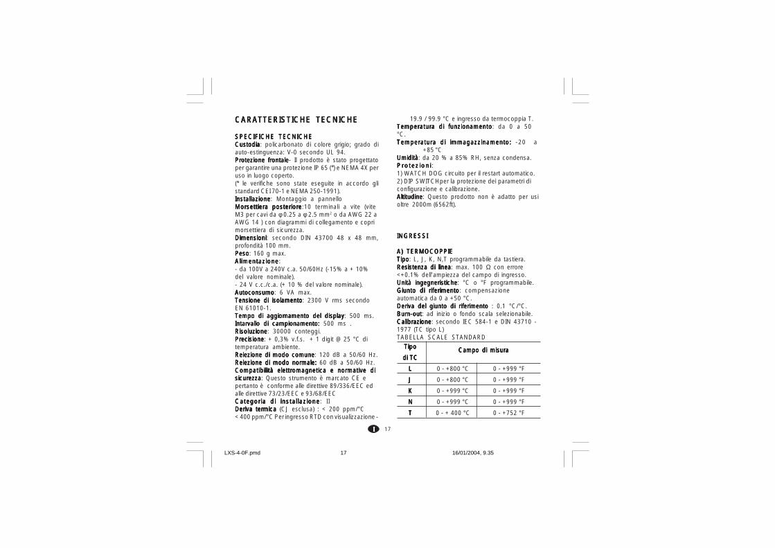
17IIIII
CARATTERISTICHE TECNICHECARATTERISTICHE TECNICHECARATTERISTICHE TECNICHECARATTERISTICHE TECNICHECARATTERISTICHE TECNICHE
SPECIFICHE TECNICHESPECIFICHE TECNICHESPECIFICHE TECNICHESPECIFICHE TECNICHESPECIFICHE TECNICHECustodiaCustodiaCustodiaCustodiaCustodia: policarbonato di colore grigio; grado diauto-estinguenza: V-0 secondo UL 94.Protezione frontaleProtezione frontaleProtezione frontaleProtezione frontaleProtezione frontale- Il prodotto è stato progettatoper garantire una protezione IP 65 (*) e NEMA 4X peruso in luogo coperto.(* le verifiche sono state eseguite in accordo glistandard CEI 70-1 e NEMA 250-1991).InstallazioneInstallazioneInstallazioneInstallazioneInstallazione: Montaggio a pannelloMorsettiera posterioreMorsettiera posterioreMorsettiera posterioreMorsettiera posterioreMorsettiera posteriore:10 terminali a vite (viteM3 per cavi da φ 0.25 a φ 2.5 mm2 o da AWG 22 aAWG 14 ) con diagrammi di collegamento e coprimorsettiera di sicurezza.DimensioniDimensioniDimensioniDimensioniDimensioni: secondo DIN 43700 48 x 48 mm,profondità 100 mm.PesoPesoPesoPesoPeso: 160 g max.AlimentazioneAlimentazioneAlimentazioneAlimentazioneAlimentazione:- da 100V a 240V c.a. 50/60Hz (-15% a + 10%del valore nominale).- 24 V c.c./c.a. (+ 10 % del valore nominale).AutoconsumoAutoconsumoAutoconsumoAutoconsumoAutoconsumo: 6 VA max.Tensione di isolamentoTensione di isolamentoTensione di isolamentoTensione di isolamentoTensione di isolamento: 2300 V rms secondoEN 61010-1.Tempo di aggiornamento del displayTempo di aggiornamento del displayTempo di aggiornamento del displayTempo di aggiornamento del displayTempo di aggiornamento del display: 500 ms.Intarvallo di campionamento: Intarvallo di campionamento: Intarvallo di campionamento: Intarvallo di campionamento: Intarvallo di campionamento: 500 ms .RisoluzioneRisoluzioneRisoluzioneRisoluzioneRisoluzione: 30000 conteggi.PrecisionePrecisionePrecisionePrecisionePrecisione: + 0,3% v.f.s. + 1 digit @ 25 °C ditemperatura ambiente.Reiezione di modo comuneReiezione di modo comuneReiezione di modo comuneReiezione di modo comuneReiezione di modo comune: 120 dB a 50/60 Hz.Reiezione di modo normale:Reiezione di modo normale:Reiezione di modo normale:Reiezione di modo normale:Reiezione di modo normale: 60 dB a 50/60 Hz.Compatibilità elettromagnetica e normative diCompatibilità elettromagnetica e normative diCompatibilità elettromagnetica e normative diCompatibilità elettromagnetica e normative diCompatibilità elettromagnetica e normative disicurezzasicurezzasicurezzasicurezzasicurezza: Questo strumento è marcato CE epertanto è conforme alle direttive 89/336/EEC edalle direttive 73/23/EEC e 93/68/EECCategoria di instal lazioneCategoria di instal lazioneCategoria di instal lazioneCategoria di instal lazioneCategoria di instal lazione: IIDeriva termicaDeriva termicaDeriva termicaDeriva termicaDeriva termica (CJ esclusa) : < 200 ppm/°C< 400 ppm/°C Per ingresso RTD con visualizzazione -
19.9 / 99.9 °C e ingresso da termocoppia T.Temperatura di funzionamentoTemperatura di funzionamentoTemperatura di funzionamentoTemperatura di funzionamentoTemperatura di funzionamento: da 0 a 50°C.Temperatura di immagazzinamento: Temperatura di immagazzinamento: Temperatura di immagazzinamento: Temperatura di immagazzinamento: Temperatura di immagazzinamento: -20 a
+85 °CUmiditàUmiditàUmiditàUmiditàUmidità: da 20 % a 85% RH, senza condensa.Protez ion iPro tez ion iPro tez ion iPro tez ion iProtez ion i :1) WATCH DOG circuito per il restart automatico.2) DIP SWITCHper la protezione dei parametri diconfigurazione e calibrazione.AltitudineAltitudineAltitudineAltitudineAltitudine: Questo prodotto non è adatto per usioltre 2000m (6562ft).
INGRESSIINGRESSIINGRESSIINGRESSIINGRESSI
A) A) A) A) A) TERMOCOPPIETERMOCOPPIETERMOCOPPIETERMOCOPPIETERMOCOPPIETipoTipoTipoTipoTipo: L, J, K, N,T programmabile da tastiera.Resistenza di lineaResistenza di lineaResistenza di lineaResistenza di lineaResistenza di linea: max. 100 Ω con errore<+0.1% dell'ampiezza del campo di ingresso.Unità ingegneristicheUnità ingegneristicheUnità ingegneristicheUnità ingegneristicheUnità ingegneristiche: °C o °F programmabile.Giunto di riferimentoGiunto di riferimentoGiunto di riferimentoGiunto di riferimentoGiunto di riferimento: compensazioneautomatica da 0 a +50 °C.Deriva del giunto di riferimento Deriva del giunto di riferimento Deriva del giunto di riferimento Deriva del giunto di riferimento Deriva del giunto di riferimento : 0.1 °C/°C.Burn-outBurn-outBurn-outBurn-outBurn-out: ad inizio o fondo scala selezionabile.CalibrazioneCalibrazioneCalibrazioneCalibrazioneCalibrazione: secondo IEC 584-1 e DIN 43710 -1977 (TC tipo L)TABELLA SCALE STANDARD
TipoTipoTipoTipoTipo
di TCdi TCdi TCdi TCdi TC
LLLLL
JJJJJ
KKKKK
NNNNN
TTTTT
0 - +800 °C
0 - +800 °C
0 - +999 °C
0 - +999 °C
0 - + 400 °C
Campo di misuraCampo di misuraCampo di misuraCampo di misuraCampo di misura
0 - +999 °F
0 - +999 °F
0 - +999 °F
0 - +999 °F
0 - +752 °F
LXS-4-0F.pmd 16/01/2004, 9.3517

18IIIII
B) RTDB) RTDB) RTDB) RTDB) RTD (RRRRResistance TTTTTemperature DDDDDetector)TipoTipoTipoTipoTipo: Pt 100 3 e fili.CorrenteCorrenteCorrenteCorrenteCorrente: 135 µA.Resistenza di lineaResistenza di lineaResistenza di lineaResistenza di lineaResistenza di linea: Compensazioneautomatica fino a 20 Ω/filo con :- errore <+0.1% dell'ampiezza del campo diingresso per il campo -19.9 a 99.9 °C.- errore non misurabile per tutti gli altri campi.Unità ingegneristicheUnità ingegneristicheUnità ingegneristicheUnità ingegneristicheUnità ingegneristiche: °C o °F programmabile.Burn-outBurn-outBurn-outBurn-outBurn-out: a fondo scala. NOTANOTANOTANOTANOTA: Uno specialecontrollo produce una segnalazione diOVERRANGE quando la resistenza di ingresso èinferiore a 15 Ω.CalibrazioneCalibrazioneCalibrazioneCalibrazioneCalibrazione: secondo DIN 43760
TABELLA SCALE STANDARD
AZIONI DI CONTROLLOAZIONI DI CONTROLLOAZIONI DI CONTROLLOAZIONI DI CONTROLLOAZIONI DI CONTROLLO
Azione regolanteAzione regolanteAzione regolanteAzione regolanteAzione regolante: PID o SMARTBanda proporzionaleBanda proporzionaleBanda proporzionaleBanda proporzionaleBanda proporzionale: da 1.0 % (se si utilizzauna sola uscita regolante) oppure 1.5 % (se siutilizzano due uscite regolanti) a 99.9 %dell'ampiezza del campo di ingresso.Impostando Pb = 0 la regolazione è del tipo ON/OFF.Isteresi Isteresi Isteresi Isteresi Isteresi (per controllo ON/OFF): da 0.1 % a 10.0% dell'ampiezza del campo di ingresso.Tempo integraleTempo integraleTempo integraleTempo integraleTempo integrale: da 10'' a 20' ; risoluzione 10secondi. Impostando un valore superiore ai 20minuti l'azione integrale risulterà esclusa.Tempo derivativaTempo derivativaTempo derivativaTempo derivativaTempo derivativa: da 0 a 9' 59''.
Precarica dell'integrale:Precarica dell'integrale:Precarica dell'integrale:Precarica dell'integrale:Precarica dell'integrale:- da 0 a 100 % per un'uscita regolante.- da -100 a 100% per due uscite regolanti (solo LHS).Tempo di ciclo dell'uscita principaleTempo di ciclo dell'uscita principaleTempo di ciclo dell'uscita principaleTempo di ciclo dell'uscita principaleTempo di ciclo dell'uscita principale:da 1 a 200 s.Tempo di ciclo uscita raffreddamentoTempo di ciclo uscita raffreddamentoTempo di ciclo uscita raffreddamentoTempo di ciclo uscita raffreddamentoTempo di ciclo uscita raffreddamento: da 1 a200 s (solo LHS).Guadagno relativo dell'azione di raffredda-Guadagno relativo dell'azione di raffredda-Guadagno relativo dell'azione di raffredda-Guadagno relativo dell'azione di raffredda-Guadagno relativo dell'azione di raffredda-mentomentomentomentomento: da 0.20 a 1.00 (solo LHS).NOTA NOTA NOTA NOTA NOTA : è possibile limitare i parametri PB, TI, TDe RCG quando la funzione SMART è abilitata.Sovrapposizione/banda mortaSovrapposizione/banda mortaSovrapposizione/banda mortaSovrapposizione/banda mortaSovrapposizione/banda morta: da - 20 % a 50% (solo LHS)
USCITEUSCITEUSCITEUSCITEUSCITE
USCITA 1 (Riscaldamento)USCITA 1 (Riscaldamento)USCITA 1 (Riscaldamento)USCITA 1 (Riscaldamento)USCITA 1 (Riscaldamento)Uscita a relè con contatto SPDT ;portata contatto 3A / 250 V c.a. su carico
resistivo.b) Tensione logica per il comando di relè a stato
solido.Stato logico 1:24 V +20% @ 1 mA.
14 V +20% @ 20 mAStato logico 0:<0.5 V
Azione dell'uscitaAzione dell'uscitaAzione dell'uscitaAzione dell'uscitaAzione dell'uscita: diretta/inversa programmabi-le (non disponibile per il modello LHS program-mato per utilizzare due uscite regolanti).
Uscita 2 - raffreddamento Uscita 2 - raffreddamento Uscita 2 - raffreddamento Uscita 2 - raffreddamento Uscita 2 - raffreddamento (solo LHS) oppureoppureoppureoppureoppureallarme 1allarme 1allarme 1allarme 1allarme 1Uscita a relè con contatto SPST ;Portata contatto 1A / 250 V c.a. su carico resistivo.Tramite ponticello interno è possibile selezionareil contatto NA o NC.
Tipo diTipo diTipo diTipo diTipo di
RTDRTDRTDRTDRTD
RTD Pt 100
RTD Pt 100
-199 - +500 °C
-19.9 - +99.9 °C
Campo di misuraCampo di misuraCampo di misuraCampo di misuraCampo di misura
-199 - +999 °F
-----
LXS-4-0F.pmd 16/01/2004, 9.3618
19IIIII
MANUTENZIONEMANUTENZIONEMANUTENZIONEMANUTENZIONEMANUTENZIONE1) TOGLIERE TENSIONE ALL'APPARECCHIO
(alimentazione, uscite a relè, ecc),2) Sfilare lo strumento dalla custodia3) Facendo uso di un aspiratore o un getto di aria
compressa a bassa pressione (max. 3 kg/cm2)rimuovere eventuali depositi di polvere esporcizia dalle ferritoie di ventilazione e daicircuiti facendo attenzione a non danneggiare icomponenti.
4) Per pulire le parti esterne in plastica o gommausare solamente uno straccio pulito edinumidito con:- alcool etilico (puro o denaturato) [C2H5OH]-alcool isopropilico (puro o denaturato)[(CH3)2CHOH]- Acqua (H2O)
5) Controllare che non vi siano morsetti allentati6) Prima di reinserire lo strumento nella sua cu-
stodia assicurarsi che l'apparecchio sia perfet-tamente asciutto.
7) Reinserire l'apparecchio e ridare tensione.
LXS-4-0F.pmd 16/01/2004, 9.3619

A. 1
DEFAULT PARAMETERSDEFAULT PARAMETERSDEFAULT PARAMETERSDEFAULT PARAMETERSDEFAULT PARAMETERS
DEFAULT OPERATIVE PARAMETERSDEFAULT OPERATIVE PARAMETERSDEFAULT OPERATIVE PARAMETERSDEFAULT OPERATIVE PARAMETERSDEFAULT OPERATIVE PARAMETERSThe control parameters can be loaded withpredetermined default values. These data are thetypical values loaded in the instrument prior toshipment from factory. To load the default valuesproceed as follows:
a ) The internal switch should be closed.b) The SMART function should be disabled.c) The safety lock must be OFF.d) The upper display will show the
processevariable while the lower display willshow the set point value or the currentmeasure.
e ) Held down pushbutton and press pushbutton; the display will show:
LMS and LHS LDS
f ) Within 10 seconds press or pushbutton.The display will show:
g) Press FUNC pushbutton; the display will show:
This means that the loading procedure has beeninitiated. After about 3 seconds the loadingprocedure is terminated and the instrumentreverts to NORMAL DISPLAY mode.
The following is a list of the default operativeparameters loaded during the above procedure:
PARAMETER DEFAULT VALUESP = minimum range-valuennn = OFFAL = minimum range-value for process alarms
0 for deviation or band alarmsHSA = 0.1 %PB = 4.0 %HS = 0.5 %ti = 04.0 (4 minutes)td = 1.00 (1 minute)IP = 30 % for one control output
0 % for two control outputsC = 20 seconds for relay output
2 seconds for SSR outputC2 = 10 seconds for P6 = AIr
4 seconds for P6 = OIL2 seconds for P6 = H2O
rC = 1.00 for P6 = AIr0.80 for P6 = OIL0.40 for P6 = H2O
OLP = 0rL = initial scale valuerH = full scale valueOLH = 100 %tOL = infinite
d.O Fd.O Fd.O Fd.O Fd.O F
L. d t.L. d t.L. d t.L. d t.L. d t. L. d t.L. d t.L. d t.L. d t.L. d t.
O F FO F FO F FO F FO F F D F L D F L D F L D F L D F L
d.O nd.O nd.O nd.O nd.O nO nO nO nO nO n D F L D F L D F L D F L D F L
LXS-A-0F.pmd 19/01/2004, 11.291

A. 2
DEFAULT CONFIGURATIONDEFAULT CONFIGURATIONDEFAULT CONFIGURATIONDEFAULT CONFIGURATIONDEFAULT CONFIGURATIONPARAMETERSPARAMETERSPARAMETERSPARAMETERSPARAMETERS
The configuration parameters can be loaded withpredetermined default values. These data are thetypical values loaded in the instrument prior toshipment from factory. To load the default valuesproceed as follows:
a ) The internal switch (V2, see fig. 9) should beopen.
b) The upper display will show:LMS - LHS LDS
c) Push the pushbutton; the lower display willshow the firmware version.
d) Mantaining the pressure on the pushbuttonpush the pushbutton also.The instrument will show
e ) Press pushbutton to select between table 1(european) or table 2 (american) defaultparameter set. The display will show:
f) Press FUNC pushbutton; the display will show:
This means that the loading procedure has beeninitiated. After about 3 seconds the loadingprocedure is terminated and the instrumentreverts to visualization as in point b).C n FC n FC n FC n FC n F
C n FC n FC n FC n FC n FA. 0 1A. 0 1A. 0 1A. 0 1A. 0 1
t b. 1t b. 1t b. 1t b. 1t b. 1 d F L d F L d F L d F L d F L
L. d t.L. d t.L. d t.L. d t.L. d t.
O F FO F FO F FO F FO F F d F L d F L d F L d F L d F L
C n FC n FC n FC n FC n F
A. 0 1A. 0 1A. 0 1A. 0 1A. 0 1
d.F Fd.F Fd.F Fd.F Fd.F F
t b. 1t b. 1t b. 1t b. 1t b. 1
L. d t.L. d t.L. d t.L. d t.L. d t.
LXS-A-0F.pmd 19/01/2004, 11.292

A. 3
The following is a list of the default parameters loaded during the above procedure:
PRODUCT LDSLDSLDSLDSLDS LMSLMSLMSLMSLMS LHSLHSLHSLHSLHS PARAMETER TABLE 1 TABLE 2 TABLE 1 TABLE 2 TABLE 1 TABLE 2
P1 1 9 1 9 1 9P2 0 °C 0 °F 0 °C 0 °F 0 °C 0 °FP3 400 °C 999 °F 400 °C 999 °F 400 °C 999 °FP4 r r r r r rP5 0 0 0 0 5 5P6 H H H H Air AirP7 r r r r r rP8 OFF OFF OFF OFF OFF OFFP9 0 0 0 0 0 0P10 0 0 0 0 0 0P11 0 0 0 0 0 0P12 10 10 10 10 10 10P13 2 2 -- -- -- --P14 ON ON ON ON ON ONP15 2 2 2 2 2 2P16 30.0 30.0 30.0 30.0 30.0 30.0P17 1.0 1.0 1.0 1.0 1.0 1.0P18 -- -- -- -- 1.5 1.5P19 -- -- -- -- OFF OFFP20 00.3 00.3 00.3 00.3 00.3 00.3P21 10 10 10 10 10 10
LXS-A-0F.pmd 19/01/2004, 11.293

Via E. Mattei, 2128100 NovaraItalyTel. +39 0321481111Fax +39 0321481112E-mail [email protected]://www.eroelectronic.com
LXS-A-0F.pmd 19/01/2004, 11.294