LCT 1000 Generation II 2006 – 2010 6 Speeddocshare02.docshare.tips/files/26013/260133832.pdf ·...
62
Transcript of LCT 1000 Generation II 2006 – 2010 6 Speeddocshare02.docshare.tips/files/26013/260133832.pdf ·...


A6LF1 Introduction
Presented by:
Mike Souza
ATRA Senior Research
Technician A6LF1 Webinar ©2014 ATRA. All Rights Reserved.


Vehicle Application
Hyundai 2009-14 Avante/HD/MD FWD L4 1.6L/1.8L (A6GF1) 2010-14 Avante/MD F/AWD L4 2.0L (A6MF1) 2011-13 Azera FWD V6 3.3L (A6LF1) V6 3.8L (A6FL2) 2014 B-Suv FWD L4 1.6L /2.0L (A6GF1) 2012-14 Elantra FWD L4 1.6L/1.8L (A6GF1) F/AWD L4 2.0L (A6MF1) 2009-14 Grandeur FWD L4 2.4L V6 2.7L (A6MF1/2) V6 3.0L/3.3L/3.5L/3.8L (A6LF1/2/3) 2011-14 i30 FWD L4 1.2L/1.6L/1.8L/2.0L (A6GF1) (A6MF1) 2012-14 i40 FWD L4 1.7L/2.0L (A6MF1) 2010-14 ix35 FWD L4 2.0L/2.4L (A6MF1) (A6LF1/2) 2013-14 Maxcruz FWD L4 2.2L V6 3.0L/3.3L (A6LF1/2/3) 2014 Mistra FWD L4 1.8L (A6GF1) L4 2.0L (A6MF1) 2009-14 Santa Fe F/4X4 L4 2.0L V6 3.3L/3.5L (A6LF2/3) L4 2.4L/2.7L (A6MF1/2) 2009-14 Sonata FWD L4 2.0LV6 3.5L (A6LF2) F/AWD L4 2.0l/2.4L (A6MF1/2) 2009-14 Tucson ix F/4X4 L4 2.0L (A6FL1/2) L4 2.0L/2.4L (A6MF1) 2012-14 Veloster FWD L4 1.6L (A6GF1) 2011-14 Veracruz F/4X4 V6 3.0L (A6FL3) 2011-13 Verna FWD L4 1.6L (A6MF1) Kia 2011-14 Carens FWD L4 1.7L/2.0L (A6MF1/2) L4 1.6L (A6GF1) 2012-14 Cee’D/Pro FWD L4 1.2L/1.6L (A6GF1) (A6MF1) 2012-14 Cerato FWD L4 1.6L (A6GF1) L4 1.8L/2.0L (A6MF1) 2011-13 Forte FWD L4 1.6L (A6GF1) L4 1.8L/2.0L/2.4L (A6MF1/2) 2009-14 Grand Carnival FWD L4 2.2L V6 3.5L (A6LF1/2/3) 2010-12 K3/K5/K7 FWD L4 2.0L/2.4L V6 2.7L (A6MF1/2) 2010 Lotze FWD L4 2.0L/2.4L (A6MF1/2) V6 3.5L (A6LF2) 2009-11 Opirus (Amanti) FWD V6 2.7L (A6MF2) V6 3.3L/3.8L (A6LF1/2) 2010-14 Optima F/AWD L4 2.0L/2.4L (A6LF1/2) (A6MF1/2) (A6GF1) 2014 Pride FWD L4 1.6L (A6GF1) 2009-14 Sorento F/4X4 L4 2.0L/2.2L V6 3.3L/3.5L (A6LF1/2/3) L4 2.4L V6 2.7L (A6MF2) 2011-14 Soul FWD L4 1.6L/2.0L (A6MF1) or (A6GF1) 2010-14 Sportage F/4X4 L4 2.0L/2.4L (A6MF1) (A6GF1) L4 2.0L (A6LF1/2)

A6LF1/2/3 Stall Speed: 2200 =/- 100 RPM 3.5/3.8/4.0L 3.3L Gear Ratio: Wide Close 1st: 4.651 4.252 2nd: 2.831 2.654 3rd: 1.842 1.804 4th: 1.386 1.386 5th: 1.000 1.000 6th: 0.772 0.772 R: 3.393 3.393 3 Balance Pistons Engine Size: A6LF1 3.3L A6LF2 3.5L / 3.8L A6LF3 4.0L Length (mm) 386 / 389 / 402 (front to rear) Torque: (kg.m) 33.5 / 36.5 / 40.0
A6MF1/2 Stall Speed: 2400 =/- 100 RPM 2.7L 2.0L Gear Ratio: Wide Close 1st: 4.639 4.162 2nd: 2.826 2.575 3rd: 1.841 1.772 4th: 1.386 1.369 5th: 1.000 1.000 6th: 0.772 0.778 R: 3.385 3.500 2 Balance Pistons Engine Size: A6MF1 2.0L / 2.4L A6MF2 2.4L / 2.7L Length (mm) 376.4 / 386.4 (front to rear) Torque: (kg.m) 23.5 / 28.5
Gear Box Comparisons

Identification Tag Location

Fluid Drain & Fill
3/8
Fill Plug
Vent
Drain Plug

Confirm that the transmission fluid temperature is 50-60 C (122-140 F) with a capable scan tool.
Capacity: A6LF1/2/3 7.8L A6MF1/2 7.1L
Fluid Level Check Closed
Open
Removed
3/8 Oil Level
Plug

Fluid Contamination & Cooler Hoses Burst
Known problems of Radiator contaminating transmission and Rubber
cooler lines bursting
Later models with rubber molded valve body cover gasket. Problems leaking
due to warping. Flat sand cover before re-using rubber molded gasket.
Apply silicone.
Side Cover Leaks
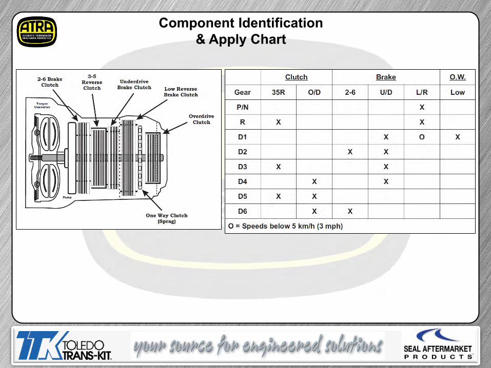
Component Identification & Apply Chart

Solenoid Function
There are 8 solenoids used in the A6LF1 transmission. 2 normally low variable force solenoids, 4 normally high variable force solenoids and 2 on/off normally low type solenoids.
NH NH NH NH On/Off NL NL

Solenoid Apply Chart
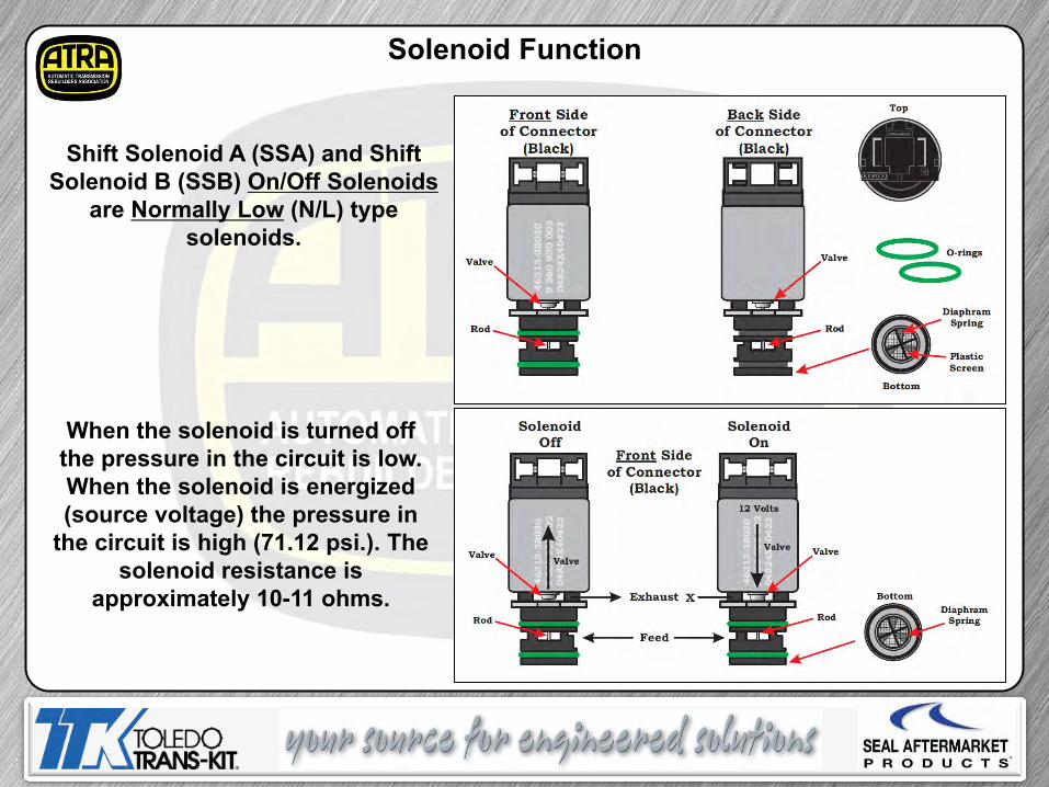
Shift Solenoid A (SSA) and Shift Solenoid B (SSB) On/Off Solenoids
are Normally Low (N/L) type solenoids.
Solenoid Function
When the solenoid is turned off the pressure in the circuit is low. When the solenoid is energized (source voltage) the pressure in
the circuit is high (71.12 psi.). The solenoid resistance is
approximately 10-11 ohms.

Solenoid Function
Line Pressure (LP) Variable Force Solenoid (VFS) is a Normally High (N/H) type
solenoid. When the solenoid is turned off the pressure in
the circuit is high.
Note: Variable Force Solenoid Connector Colors are model dependent.
When the solenoid is energized (50 - 850 mA) the pressure in the circuit is varied (1.42 - 72.54 psi.).
The solenoid resistance is approximately 5.1 ohms.

Solenoid Function
3-5-Reverse, Underdrive and Overdrive Variable Force Solenoid (VFS) are
Normally High (N/H) type solenoids.
When the solenoid is turned off the pressure in the circuit is high. When the solenoid is energized (50 - 850 mA) the pressure in the
circuit is low (1.42 - 72.54 psi.). The solenoid resistance is approximately 5.1 ohms.
Under Drive
3-5 Reverse
Over Drive

Solenoid Function
Torque Converter and 2-6 Brake Variable Force Solenoid (VFS) are
Normally Low (N/L) type solenoids.
When the solenoid is turned off the pressure in the circuit is low. When the solenoid is energized (50 - 850
mA) the pressure in the circuit is high (1.42 - 72.54 psi.). The solenoid
resistance is approximately 5.1 ohms.
Lock Up Variable Force Solenoid
2 – 6 Variable Force Solenoid

Inhibitor Switch
TCM Data (may not be provided by scan tool)
Adjustment Bolts Neutral Alignment
Pin ID
Voltage Check

Internal Harness Removal & Connector ID
The retainer for the Internal Harness Connector must be removed prior to removing the harness. Once the retainer is remove from the connector the harness can be pushed down into the transmission and remove from the inside.
Solenoid & Sensor Resistance: Oil Temperature:1.9k ohms @ 24.4 C (76 F) Input Speed Sensor (ISS): 3.8m ohms Output Speed Sensor (OSS): 5.8m ohms Variable Force Solenoids VFS: 5.1 ohms Shift Solenoids (on/off): 10-11 ohms
1: N/A 10: Solenoid PWR 1 2: DC VFS (lockup) 11: 2-6 VFS 3: OSS PWR 12: SSB 4: OSS SIG 13: Oil Temp Sensor PWR 5: Solenoid PWR 2 14: ISS PWR 6: 3-5-R VFS 15: N/A 7: O/D VFS 16: U/D VFS 8: ISS SIG 17: LP VFS (line) 9: Oil Temp Sensor GND 18: SSA

Valve Body Removal

Fluid Temperature Sensor
Voltage: Max. 3.26V @ - 40 C (104 F) Voltage: Min. 0.29V @ 150 C (302 F) Sensor Failsafe; Fixed to 4th Gear 1st & 2nd will be Prohibited Default Value 80 C (176 F) May Not Turn On MIL

Input & Output Speed Sensors
Integrated as one assembly
Voltage: Input 1.62-0.79V Output 1.63-0.78V Current Type: Low 7 mA to High 14 mA Type: Hall Effect 2 pin 9 Volt Power Signal Length: Input 52.7-52.9 mm (2.07-2.08” in.) Output 33.6-33.8 mm (1.32-1.33”) Air Gap: Input 0.95-1.65 mm (0.037-0.065” in.) Output 0.25-1.9 mm (.010-.075”) Input Speed Sensor Resistance: 3.8m ohms Output Speed Sensor Resistance: 5.8m ohms Input / Output Sensor Failsafe: 4th Gear Hold in Drive, 2nd - 4th Manual Shift (Sport)

Output Speed Sensor (OSS)
Monitors Transfer Drive Gear
Input Speed Sensor (ISS) Monitors Overdrive
Clutch Drum
Input & Output Speed Sensors

Case Air Checks
1. To Cooler 2. From Cooler 3. Lubrication (rear) 4. Overdrive Pressure 5. Reducing Pressure (Red 2) 6. Reducing Pressure (Red 1) 7. From Damper Pressure 8. To Damper Pressure 9. Lubrication (front) 10. 3-5-R Clutch Pressure 11. 2-6 Brake 12. From Oil Pump 13. To Oil Pump 14. Under-drive Pressure 15. Low & Reverse Pressure
7
8
9
10
11
12
13
1
2
3
4
5
6
Front of Trans
14
15

Known Valve Body Wear At Low Mileage
Outer Valve Body Assembly

Outer Valve Body Assembly
Rubber Faces Up

Center Valve Body Assembly

Center Valve Body Assembly

Center Valve Body Assembly

Inner Valve Body Assembly

Inner Valve Body Assembly
Valve Body Wear As Low As 35,000 K
No Repair Available

Clutch End Play Checks

Clutch End Play Checks

Clutch End Play Checks “Alternative Procedure”
Place the legs of the H-Gauge on the case at the pump to case mating area. Slide the measuring bar down to the compressed 2-6 Brake Clutch Cushion Plate.

Clutch End Play Checks “Alternative Procedure”
Then flip the H-Gauge over and place onto the pump at the to case mating area. Measure the clearance at the apply piston.

Clutch End Play Checks

Clutch End Play Checks

Unit End Play Specifications (Front)
Place the legs of the H-Gauge on the case at the pump to case mating area. Slide the measuring bar down to the bottom of the 3-5-R drum where the thrust washer would make contact. Then flip the H-Gauge over and place onto the pump at the to case mating area. With the selective thrust washer in place measure the amount of end play present.

Unit End Play Specifications (Rear)
Place the legs of the H-Gauge on the case at the rear cover to case mating area. Slide the measuring bar down until it makes contact with the thrust bearing on the bottom of the O/D drum.
Then flip the H-Gauge over and place onto the rear cover at the case to cover mating area.
With the selective race in place measure the amount of end play present.

Low/Reverse One Way Clutch (sprag) Rotation
Turn Held
Planet Turns (Freewheels) Counter Clockwise When Viewed From Back Of Case

Low/Reverse One Way Clutch (sprag) Rotation
There are no identification marks On the side that faces out.
The word “Front” is marked on the side that faces towards the pump.
“Front”

There is a problem with inner under drive lip seal prematurely wearing. This may cause a
delay or slip in drive. This similar to the clutch seal wear found in the early 1999
Subaru 4EAT Phase II transmission.
Inner Seal Worn
Under Drive Brake Piston
Under Drive Brake Piston Inner Seal Failure
Under Drive Brake Drum
Rough Area
The only difference with this drum is it may be too rough to sand down smooth.
the drum will have to be replaced.

Pressure Tap Identification Top of Case Front Side of Case
Back of Case Bottom of Case
Damper Release/Apply 3-5-Reverse Clutch /2-6 Brake Clutch
Low Reverse Brake Clutch
Overdrive Clutch / Reducing Pressure 1 / Reducing Pressure 2 Under Drive Brake Clutch

Pressure Testing

Solenoid Function
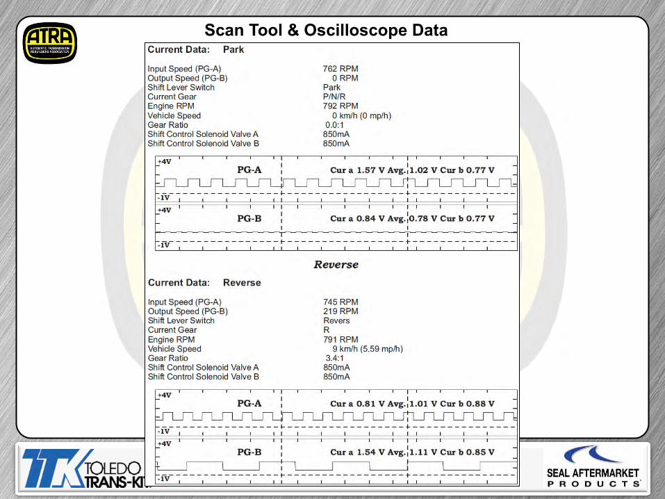
Scan Tool & Oscilloscope Data

Scan Tool & Oscilloscope Data

Scan Tool & Oscilloscope Data

Scan Tool & Oscilloscope Data

Scan Tool & Oscilloscope Data

TCM Learning Procedure
When harsh shifts have occurred or parts related with the transaxle are replaced. TCM learning should be performed. TCM learning is required when; Transaxle assembly is replaced TCM is replaced TCM is updated Note: ATF temperature must be: 60-115 C (140-239 F) TCM relearn procedure; A: Stop learning. (engagements) 1. Shift from Neutral to Park 4 times or more while depressing brake.
B: Driving learning. 1. Drive through all gears in D range from a stop at a fixed 15-30% throttle opening. 2. Down shift from 6th to 5th, 5th to 4th, 4th to 3rd, 3rd to 2nd, 2nd to 1st. 3. Repeat 4 times or more.

All Wheel Drive
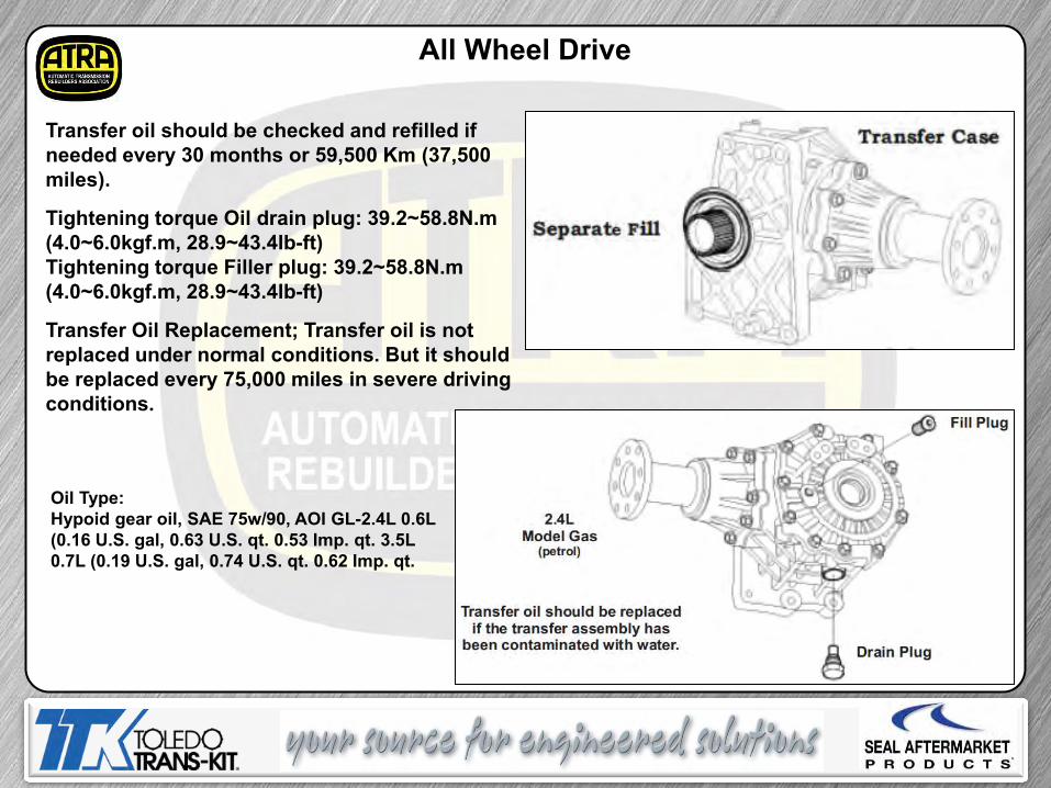
All Wheel Drive
Transfer oil should be checked and refilled if needed every 30 months or 59,500 Km (37,500 miles).
Tightening torque Oil drain plug: 39.2~58.8N.m (4.0~6.0kgf.m, 28.9~43.4lb-ft) Tightening torque Filler plug: 39.2~58.8N.m (4.0~6.0kgf.m, 28.9~43.4lb-ft)
Transfer Oil Replacement; Transfer oil is not replaced under normal conditions. But it should be replaced every 75,000 miles in severe driving conditions.
Oil Type: Hypoid gear oil, SAE 75w/90, AOI GL-2.4L 0.6L (0.16 U.S. gal, 0.63 U.S. qt. 0.53 Imp. qt. 3.5L 0.7L (0.19 U.S. gal, 0.74 U.S. qt. 0.62 Imp. qt.

4 Pinion Differential Gear Set
The differential has a 4 pinion gear set up to handle high torque levels in a compact designed transmission. • This creates 50% more capacity than other differentials of the same size. • Differential side gears & pinion gear backlash .025 - .150mm (.0009 - .0059”).
O-Ring

4WD System Power Flow
Auto Mode: While driving in the 4WD AUTO mode, the vehicle operates similar to conventional 2WD vehicle under normal driving conditions. If the system determines a need for the 4WD mode, the engine’s driving torque is distributed to all four wheels automatically without driver control. While driving on normal roads and pavement, the vehicle reacts similar to conventional 2WD vehicle.

Lock Mode: 4WD lock mode is used for climbing or descending sharp grades, off-road driving, driving on sandy and muddy roads, etc., for maximize traction. This mode will automatically begin to deactivate at speeds above 30 km/h (19 mph) and shifts to 4WD AUTO mode at speed above 40 km/h (25 mph). If the vehicle decelerates below 30 km/h (19 mph), the transfer mode is shifted into 4WD LOCK mode again.
4WD System Power Flow

The Electronic Control Unit (ECU) use inputs (listed below) to control the amount of current needed to apply the electromagnetic clutch assembly located in the 4 wheel drive couple mounted onto the rear differential. • Input torque (Throttle position sensor) • Cornering situation (Steering angle sensor) • Vehicle speed and different wheel speed front & rear (Wheel speed sensor) • Braking situation (Brake signal and ABS signal)
4WD System Power Flow

The EMC (Electric Magnetic Clutch) operates the primary clutch controlling the cam's opening gap. This Controls the slip of inner & outer plate to optimize front & rear driving force.
42 4WD System Power Flow

Note: Transfer gear preload is known to be too tight from factory, this must be checked during rebuild.
Transfer Gear Preload

A6LF1 Webinar ©2014 ATRA. All Rights Reserved.

When you received the email invitation to the
webinar, there should be a place to click and
download the Adobe (pdf file) of the presentation
handout material.
Also there is an icon that you can click on to be
placed onto the email list for future webinars. An
invitation will be emailed automatically when future webinars are
scheduled.
You can also invite a friend.
Register for your time zone here.

If you see material that is not shown in your handout just double click on the camera icon at the top right of your screen and it will leave a picture (jpg. file) on your desktop.