
Longitudinal Coordination of Care LCP SWG Monday, August 12, 2013.
LCP Coordination PanelOperations & Maintenance Manual
Table of ContentsOverview ................................................................................... 1
NEC® Requirements for Selective Coordination ........................ 2
LCP Datasheet .......................................................................... 3
CCMR Series POWR-PRO® Fuses - Datasheet ......................... 5
JTD Series Indicator POWR-PRO® Fuses - Datasheet ............... 8
Cutler-Hammer - BAB Datasheet ..............................................12
Cutler-Hammer - GHB Datasheet .............................................14
Recommended Maintenance ..................................................16
Frequently Asked Questions .....................................................17
Glossary of LCP Coordination Panel Options ...........................19

©2017 Littelfuse POWR-GARD® Products1-800-TEC-FUSE | www.littelfuse.com
LCP Fused Coordination Panel Operations & Maintenance
1
OVERVIEW
The Littelfuse LCP Selective Coordination Panel uses circuit breakers in series with fuses and fuse holders to respond to overloads and short-circuits, respectively, in order to achieve selective coordination. The National Electric Code® (NEC) mandates that certain systems be selectively coordinated (specifics are highlighted on pg. 02), and the LCP Coordination Panel is specifically designed to meet those requirements.
Each unit is custom-built based on an engineering specification, and official technical drawings are carefully reviewed and approved by the specifying engineer before the product is manufactured in order to ensure it meets the requirements. The purpose of this document is to provide technical information about the LCP Coordination Panel and address potential questions end-users may have.

©2017 Littelfuse POWR-GARD® Products1-800-TEC-FUSE | www.littelfuse.com
LCP Fused Coordination Panel Operations & Maintenance
2
NEC® REQUIREMENTS FOR SELECTIVE COORDINATION
Healthcare Essential Electrical Systems (NEC® 517.26)References Article 700 Emergency Systems. The following facilities will have essential lighting and power systems for life safety:• Clinics• Hospitals• Nursing homes • Medical and dental offices• Outpatient facilities• Other healthcare facilities
Elevators (NEC® 620.62)May include the following circuits per the local agency having jurisdiction:• Elevators• Dumbwaitor• Escalator• Moving walks• Platform lifts• Stairway chair lifts
Emergency Systems (NEC® 700.27)May include the following circuits per the local agency having jurisdiction:• Emergency lighting• Ventilation• Fire detection and alarm systems• Elevators• Fire pumps• Industrial processes where interruption would be hazardous
Legally Required Standby Systems (NEC® 701.18)May include the following circuits per the local agency having jurisdiction:• Heating and refrigeration• Communications systems• Ventilation and smoke removal• Sewage disposal
Critical Operations Power Systems (NEC® 708.54)High reliability for critical operations during natural disasters and other threats. May include the following circuits per the local agency having jurisdiction:• Power systems• HVAC• Fire alarm• Security• Communications

©2017 Littelfuse POWR-GARD® Products1-800-TEC-FUSE | www.littelfuse.com
LCP Fused Coordination Panel Operations & Maintenance
3
Features/Benefits• Meets NEC® requirements• Class CC and J fuse holders have built-in
open-circuit indication• Fast-acting UL Listed fuses protect against short circuits • Feed through/sub feed lugs and 84-circuit
configuration available• Ground and neutral bars• Copper bus standard
Advanced Design Options• MLO, Main Circuit Breaker, or Main Fused Pullout device• Fused Class T branch circuit pullout• Spare fuse cabinet accessory (holds six spare fuses)• TVSS overvoltage protection • Any NEMA enclosure required• High amperage sub-fed branch breakers (J60A) • Unique Specifier Tool (see pg. 146) to easily identify panel
configurations from tens of thousands of options
SpecificationsVoltage Ratings 120/208, 120/240, 277/480 VACMain Bus Rating 100 A - 400 A StandardConductor Terminals 6 AWG - 300 kcmilUL Listed UL 67 Panel boards and UL 50 Enclosures
Web ResourcesFor more information, visit: littelfuse.com/lcp
DescriptionThe Littelfuse® Coordination Panel provides a simple, time-saving solution for circuits that require selective coordination. This UL Listed product saves time and money, and increases safety by minimizing system downtime.
Applications• Elevators • Hospitals• Hotel and Entertainment Industry• Amusement Parks and Stadiums
Code RequirementsSystems required by the NEC® to be selectively coordinated include:
• Health Care Essential Electrical Systems (NEC 517.26)• Elevators (NEC 620.62)• Emergency Systems (NEC 700.27)• Legally Required Standby Systems (NEC 701.18)• Critical Operations Power Systems (NEC 708.54)
† Fuses quoted separately to meet panel specifications. Coordination for breakers >60 A depends on upstream and downstream devices. More specialized configurations are also available. Contact factory for more information.
Note: The Littelfuse LPS and LCP products are custom designed products that fall outside standard specifications.
Customizable Options (select one from each column)NUMBER
OF CIRCUITS
VOLTAGE MAIN DEVICESNEUTRAL RATING
PANEL MOUNTING
PANEL DOOR
FUSE HOLDERS
BRANCH CIRCUIT PROTECTION DEVICES
(1-3 POLE)†
PANEL FEED
OPTIONAL LUGSSTANDARDENCLOSURE
RATING
2 - 42
120/208 V 3P, 4 W
120/240 V 1P, 3 W
277/480 V 3P, 4 W
125, 225, 400 or 600 A MLO
Up to 600 A MCB or Main Fuse
Pullout
100%
200%
Surface
Flush
Standard
Door-in-door
30 A Class CC
60 A Class J
10 A- 60 A fused circuit breaker
60 A-200 A
fused pullouts
Sub-fed circuit breakers >60 A
(not fused)
Top
Bottom
None
Sub-Fed (MLO panels)
Feed-Through
NEMA 1
NEMA 3R
NEMA 4X
LCP DATASHEET

©2017 Littelfuse POWR-GARD® Products1-800-TEC-FUSE | www.littelfuse.com
LCP Fused Coordination Panel Operations & Maintenance
4
LCP DATASHEET
Inner Line
GND Bus
Neutral Detail
Neutral Detail
(6 AWG - 300 kcmil) Cu/AlIncoming Main Lugs
Cutler HammerGHB (480 V) or BAB (208 V)Circuit Breakers(or Pullouts)
LPSC001ID POWR-SafeDead front Class CC 600 VACFuseholder for use with LittelfuseCCMR, KLKR or KLDR Class CC fuses or POWR-Safe LPSJ holders for use the Class J fuses. (Fuses not included)
LPSC001ID POWR-SafeDead front Class CC 600 VACFuseholder for use with LittelfuseCCMR, KLKR or KLDR Class CC fuses or POWR-Safe LPSJ holders for use the Class J fuses. (Fuses not included)
Front TrimType 1 (NEMA) Enclosure
Front View with Front RemovedHinged Door with Catch and Lock
Dimensions in mm [inches]
Dimensions in mm [inches]
GND Bus
Inner Line
(6 AWG - 300 kcmil) Cu/AlIncoming Main Lugs
Cutler HammerGHB (480 V) or BAB (208 V)Circuit Breakers(or Pullouts)
Front TrimType 1 (NEMA) EnclosureFront View with Front Removed Hinged Door with
Catch and Lock
[6.00]152.4
[6.00]152.4
[28.00]711.2
[28.00]711.2
[36.00]914.4
[24.00]609.6
[16.50]419.1
[28.00]711.2
[42.00]1066.8
[30.00]762
[16.50]419.1
[9.69]246.06
[8.94]227.01
[28.00]711.2
[9.69]246.06
[8.94]227.01
Dimensions mm (inches)Standard Coordination Panel Board (up to 30 circuits)
Standard Coordination Panel Board (31-42 circuits)
Inner Line
GND Bus
Neutral Detail
Neutral Detail
(6 AWG - 300 kcmil) Cu/AlIncoming Main Lugs
Cutler HammerGHB (480 V) or BAB (208 V)Circuit Breakers(or Pullouts)
LPSC001ID POWR-SafeDead front Class CC 600 VACFuseholder for use with LittelfuseCCMR, KLKR or KLDR Class CC fuses or POWR-Safe LPSJ holders for use the Class J fuses. (Fuses not included)
LPSC001ID POWR-SafeDead front Class CC 600 VACFuseholder for use with LittelfuseCCMR, KLKR or KLDR Class CC fuses or POWR-Safe LPSJ holders for use the Class J fuses. (Fuses not included)
Front TrimType 1 (NEMA) Enclosure
Front View with Front RemovedHinged Door with Catch and Lock
Dimensions in mm [inches]
Dimensions in mm [inches]
GND Bus
Inner Line
(6 AWG - 300 kcmil) Cu/AlIncoming Main Lugs
Cutler HammerGHB (480 V) or BAB (208 V)Circuit Breakers(or Pullouts)
Front TrimType 1 (NEMA) EnclosureFront View with Front Removed Hinged Door with
Catch and Lock
[6.00]152.4
[6.00]152.4
[28.00]711.2
[28.00]711.2
[36.00]914.4
[24.00]609.6
[16.50]419.1
[28.00]711.2
[42.00]1066.8
[30.00]762
[16.50]419.1
[9.69]246.06
[8.94]227.01
[28.00]711.2
[9.69]246.06
[8.94]227.01
Note: The Littelfuse LPS and LCP products are custom designed products that fall outside standard specifications.
Dimensions may change depending on panel components. More specialized configurations are also available. Contact factory for more information.

©2017 Littelfuse POWR-GARD® Products1-800-TEC-FUSE | www.littelfuse.com
LCP Fused Coordination Panel Operations & Maintenance
5
CCMR SERIES POWR-PRO® FUSES - DATASHEET 600 Vac • Dual Element • Time-Delay • 2/10-60 A
Web ResourcesTC Curves, downloadable CAD drawings and other technical information: www.littelfuse.com/ccmr
Recommended FuseholdersLFC600 Series L60030C Series LFPSC Touch-Safe Series
Peak Let-Thru Curve
Ordering Information
1000
0
1000
00
2000
00100
1000
100
1000
10000
100000
1000000
60 A
30 A20 A15 A12 A10 A6 1/4 A
4 A2 A
CCMR
AMPERAGE RATINGS2/10 1 2 3 1/2 6 1/4 12 351/4 1 1/4 2 1/4 4 7 15 403/10 1 4/10 2 1/2 4 1/2 7 1/2 17 1/2 451/2 1 1/2 2 8/10 5 8 20 506/10 1 6/10 3 5 6/10 9 25 608/10 1 8/10 3 2/10 6 10 30
SERIES AMPERAGE ROHS CATALOG NUMBER ORDERING NUMBERCCMR 10 • CCMR010 CCMR010.TXPCCMR 45 CCMR045 CCMR045.T
DescriptionThe CCMR series is ideal for space saving protection of motors up to 40 hp*. It was designed specifically to withstand sustained starting currents of small motors. The CCMR 60 fuse is the smallest 60 A fuse available rated at 600 V. Compared to other UL Listed fuses, Class CC fuses are the most current-limiting, rating for rating.
Features/Benefits• POWR-PRO Performance
• Extremely current-limiting
• Ratings up to 60 Amps
• 300 kA Interrupting Rating (self-certified)
Applications• Motor and motor branch circuit protection
SpecificationsVoltage Rating AC: 600 V DC: 250 V (CCMR 2/10– 2 A)
(CCMR 41/2– 10 A) (CCMR 35– 60 A) 300 V (CCMR 21/4– 4 A) 500 V (CCMR 12– 30 A)
Amperage Rating 2/10 – 60 AInterrupting Rating AC: 200 kA rms symmetrical
300 kA Littelfuse self-certified DC: 20 kAApprovals AC: Standard 248-4, Class CC
UL Listed 2/10-30 A (File: E81895) Standard 248, Class CD UL Listed 35-60 A (File: E81895) CSA Certified (File: LR29862)
DC: Littelfuse self-certified Environmental RoHS Compliant (except 35-60 A)Country of Origin Mexico
©2017 Littelfuse POWR-GARD® Products1-800-TEC-FUSE | www.littelfuse.com
LCP Fused Coordination Panel Operations & Maintenance
6
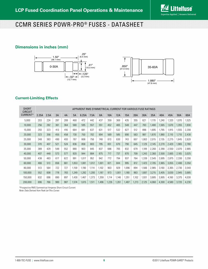
Current-Limiting Effects
1.880" (47.8 mm)
.850"(21.6 mm)
1.50"(38.1 mm)
.50"(12.7 mm)
.41"(10.3 mm)
.25"(6.4 mm)
.125"(3.2 mm)
35-60A0-30A
CCMR SERIES POWR-PRO® FUSES - DATASHEET
Dimensions in inches (mm)
SHORT CIRCUIT
CURRENT*
APPARENT RMS SYMMETRICAL CURRENT FOR VARIOUS FUSE RATINGS
2.25A 2.5A 3A 4A 5A 6.25A 7.5A 8A 10A 12A 15A 20A 30A 35A 40A 45A 50A 60A
5,000 203 224 287 289 460 472 442 437 359 369 435 355 621 1,170 1,240 1,320 1,070 1,525
10,000 256 282 361 364 580 595 557 551 452 465 548 447 783 1,480 1,565 1,670 1,355 1,930
15,000 293 323 413 416 664 681 637 631 517 532 627 512 896 1,695 1,795 1,915 1,555 2,200
20,000 323 356 455 458 730 750 702 694 569 585 690 563 987 1,870 1,980 2,110 1,710 2,430
25,000 348 383 490 493 787 808 756 748 613 630 743 607 1,063 2,015 2,135 2,275 1,845 2,620
30,000 370 407 521 524 836 858 803 795 651 670 790 645 1,129 2,145 2,270 2,420 1,965 2,780
35,000 389 429 548 552 880 903 845 837 686 705 832 679 1,189 2,260 2,390 2,550 2,070 2,885
40,000 407 448 573 577 920 944 884 875 717 737 870 709 1,243 2,360 2,500 2,665 2,165 3,025
50,000 438 483 617 622 991 1,017 952 942 772 794 937 764 1,339 2,545 2,695 2,875 2,330 3,200
60,000 466 513 656 661 1,053 1,081 1,012 1,001 821 844 995 812 1,423 2,705 2,865 3,055 2,480 3,350
80,000 513 564 722 727 1,159 1,190 1,114 1,102 903 929 1,096 894 1,566 2,985 3,160 3,365 2,730 3,540
100,000 552 608 778 783 1,249 1,282 1,200 1,187 973 1,001 1,180 963 1,687 3,215 3,405 3,630 2,945 3,685
150,000 632 696 890 897 1,430 1,467 1,373 1,359 1,114 1,146 1,351 1,102 1,931 3,685 3,905 4,160 3,375 4,030
200,000 696 766 980 987 1,574 1,615 1,511 1,496 1,226 1,261 1,487 1,213 2,125 4,060 4,300 4,580 3,720 4,230
*Prospective RMS Symmetrical Amperes Short-Circuit CurrentNote: Data Derived from Peak Let-Thru Curves

©2017 Littelfuse POWR-GARD® Products1-800-TEC-FUSE | www.littelfuse.com
LCP Fused Coordination Panel Operations & Maintenance
7
CCMR SERIES POWR-PRO® FUSES - DATASHEET
Time Current Curves
- THIS DATA IS GENERATED IN EXCEL -
1000 900 800 700 600 500
400
300
200
100 90 80 70 60 50
40
30
20
10 9 8 7 6 5
4
3
2
1 0.9 0.8 0.7 0.6 0.5
0.4
0.3
0.2
0.1 0.09 0.08 0.07 0.06 0.05
0.04
0.03
0.02
0.01
1000 900 800 700 600 500
400
300
200
100 90 80 70 60 50
40
30
20
10 9 8 7 6 5
4
3
2
1 0.9 0.8 0.7 0.6 0.5
0.4
0.3
0.2
0.1 0.09 0.08 0.07 0.06 0.05
0.04
0.03
0.02
0.01
1000 900 800 700 600 500
400
300
200
100 90 80 70 60 50
40
30
20
10 9 8 7 6 5 4 3 2 1 0.9 0.8 0.7 0.6 0.5
0.4
0.3
0.2
0.1
1000 900 800 700 600 500
400
300
200
100 90 80 70 60 50
40
30
20
10 9 8 7 6 5 4 3 2 1 0.9 0.8 0.7 0.6 0.5
0.4
0.3
0.2
0.1
- 6-1/4A
- 7-1/2A
- 5A
&'(($)!%")%+#4$($,%
!"#$%")%,$&
3)5,
%
BASIS FOR DATA:
TEST VOLTAGE: 600V TIME CONSTANT/POWER FACTOR: FUSE CATALOG NUMBER:
DRAWN BY:
DATE:
REVISION: DRAWING NO.: SHEET !"#$%&'(($)!%&*+(+&!$(",!"&%&'(-$,%
."!!$./',$0%")&1%&*"&+230%".1%',+%
LLL
12/21/12
B 6 OF 8
FCC01-CCMRP
CCMRP 2/10A - 30A
- THIS DATA IS GENERATED IN EXCEL -
1000 900 800 700 600 500
400
300
200
100 90 80 70 60 50
40
30
20
10 9 8 7 6 5
4
3
2
1 0.9 0.8 0.7 0.6 0.5
0.4
0.3
0.2
0.1 0.09 0.08 0.07 0.06 0.05
0.04
0.03
0.02
0.01
1000 900 800 700 600 500
400
300
200
100 90 80 70 60 50
40
30
20
10 9 8 7 6 5
4
3
2
1 0.9 0.8 0.7 0.6 0.5
0.4
0.3
0.2
0.1 0.09 0.08 0.07 0.06 0.05
0.04
0.03
0.02
0.01
1000 900 800 700 600 500
400
300
200
100 90 80 70 60 50
40
30
20
10 9 8 7 6 5 4 3 2 1 0.9 0.8 0.7 0.6 0.5
0.4
0.3
0.2
0.1
1000 900 800 700 600 500
400
300
200
100 90 80 70 60 50
40
30
20
10 9 8 7 6 5 4 3 2 1 0.9 0.8 0.7 0.6 0.5
0.4
0.3
0.2
0.1
- 20A
- 25A
- 30A
&'(($)!%")%+#4$($,%
!"#$%")%,$&
3)5,
%
BASIS FOR DATA:
TEST VOLTAGE: 600V TIME CONSTANT/POWER FACTOR: FUSE CATALOG NUMBER:
DRAWN BY:
DATE:
REVISION: DRAWING NO.: SHEET !"#$%&'(($)!%&*+(+&!$(",!"&%&'(-$,%
."!!$./',$0%")&1%&*"&+230%".1%',+%
LLL
12/21/12
B 8 OF 8
FCC01-CCMRP
CCMRP 2/10A - 30A
- THIS DATA IS GENERATED IN EXCEL -
1000 900 800 700 600 500
400
300
200
100 90 80 70 60 50
40
30
20
10 9 8 7 6 5
4
3
2
1 0.9 0.8 0.7 0.6 0.5
0.4
0.3
0.2
0.1 0.09 0.08 0.07 0.06 0.05
0.04
0.03
0.02
0.01
1000 900 800 700 600 500
400
300
200
100 90 80 70 60 50
40
30
20
10 9 8 7 6 5
4
3
2
1 0.9 0.8 0.7 0.6 0.5
0.4
0.3
0.2
0.1 0.09 0.08 0.07 0.06 0.05
0.04
0.03
0.02
0.01
1000 900 800 700 600 500
400
300
200
100 90 80 70 60 50
40
30
20
10 9 8 7 6 5 4 3 2 1 0.9 0.8 0.7 0.6 0.5
0.4
0.3
0.2
0.1
1000 900 800 700 600 500
400
300
200
100 90 80 70 60 50
40
30
20
10 9 8 7 6 5 4 3 2 1 0.9 0.8 0.7 0.6 0.5
0.4
0.3
0.2
0.1
- 15A
- 10A
- 8A
&'(($)!%")%+#4$($,%
!"#$%")%,$&
3)5,
%
BASIS FOR DATA:
TEST VOLTAGE: 600V TIME CONSTANT/POWER FACTOR: FUSE CATALOG NUMBER:
DRAWN BY:
DATE:
REVISION: DRAWING NO.: SHEET !"#$%&'(($)!%&*+(+&!$(",!"&%&'(-$,%
."!!$./',$0%")&1%&*"&+230%".1%',+%
LLL
12/21/12
B 7 OF 8
FCC01-CCMRP
CCMRP 2/10A - 30A
1000900800700600500
1000900800700600500
1000009000080000700006000050000
40000
30000
20000
1000090008000700060005000
4000
3000
2000
1000900800700600500
400
300
200
100908070605040302010
500400
300
200
100908070
500400
300
200
100908070
- 35A
- 40A
- 45A
- 50A
- 60A70605040
30
20
10
70605040
30
20
10
60A
10987654
3
2
10987654
3
2TIMEIN
SECO
NDS
10.90.80.70.60.50.4
0.3
0 2
10.90.80.70.60.50.4
0.3
0 20.2
0.10.090.080.070.060.050.04
0.03
0.2
0.10.090.080.070.060.050.04
0.03
0.02
0.01
0.02
0.01
1000009000080000700006000050000
40000
30000
20000
1000090008000700060005000
4000
3000
2000
1000900800700600500
400
300
200
100908070605040302010
CURRENT IN AMPERES
BASIS FOR DATA:
TEST VOLTAGE: TIME CONSTANT/POWER FACTOR: FUSE CATALOG NUMBER:
DRAWN BY:DATE:REVISION:DRAWING NO.: SHEET TIME CURRENT CHARACTERISTIC CURVES
LITTELFUSE, INC.CHICAGO, IL. USA
LLL
8/25/2008
A9 OF 9
FCC01-CCMR
CCMR 2/10A - 30A
- THIS DATA IS GENERATED IN EXCEL -
TIME CURRENT CHARACTERISTIC CURVES FCC01 CCMR

©2017 Littelfuse POWR-GARD® Products1-800-TEC-FUSE | www.littelfuse.com
LCP Fused Coordination Panel Operations & Maintenance
8
JTD SERIES INDICATOR POWR-PRO® FUSES - DATASHEET 600 VAC • Time Delay • 8/10 – 600 A
AMPERAGE RATINGS8⁄10 21⁄4 41⁄2 10 35 90 225 6001 21⁄2 5 12 40 100 250 –
11⁄4 2 8⁄10 5 6⁄10 15 45 110 300 –11⁄2 3 6 171⁄2 50 125 350 –16⁄10 32 ⁄10 7 20 60 150 400 –18⁄10 3 1⁄2 8 25 70 175 450 –
2 4 9 30 80 200 500 –
DescriptionThe Littelfuse POWR-PRO® JTD_ID Indicator Class J fuse provides visual blown fuse indication and maximum protection in a compact package. The current-limiting time delay JTD_ID offers a patented design which reduces nuisance fuse openings.
Features/Benefits• POWR-PRO® Performance • Current-Limiting• IEC Type 2 Protection• Indication and non-indication version available• Indicating and DIN mount holders available
Applications• Fused combination motor controllers and motor
control centers• Transformer protection• Protection for series rated molded case
circuit-breaker panels• General purpose circuits
SpecificationsVoltage Ratings AC: 600 V DC: 300 V (8⁄10 –100 A)
500 V (110–600 A)Amperage Range 8 ⁄10–600 AInterrupting Rating AC: 200 kA rms symmetrical
300kA rms symmetrical (Littelfuse self-certified)
DC: 20 kAMaterial Body: Melamine Caps: Nickel-plated Bronze (8⁄10–60 A)
Brass (70–200 A) Brass Cap with Copper Blade (225–600 A)Approvals AC: Standard 248-8, Class J
UL Listed (File: E81895) CSA Certified (File: LR29862)
DC: Littelfuse self-certifiedCountry of Origin Mexico
Ordering Information
Web Resources Time-current curves, data sheets and additional technical information: littelfuse.com/jtd
Recommended Fuse HoldersLFJ60 Series LFPSJ Series (8⁄10 –60 A)
TYPE SERIES AMPERAGE CATALOG NUMBER
ORDERING NUMBER
INDICATING JTD_ID 60 JTD60ID 0JTD060.TXIDNON-INDICATING JTD 60 JTD60 0JTD060.T

©2017 Littelfuse POWR-GARD® Products1-800-TEC-FUSE | www.littelfuse.com
LCP Fused Coordination Panel Operations & Maintenance
9
JTD SERIES INDICATOR POWR-PRO® FUSES - DATASHEET
A
C
DG F
EHA
BCD
Fig. 1 Fig. 2
Dimensions Inches (mm)
AMPERAGE FIG. NO.DIMENSIONS INCHES (mm)
A B C D E F G H
1 – 30 1 21⁄4 (57.2) — 1⁄2 (12.7) 13⁄16 (20.6) — — — —
35 – 60 1 23⁄8 (60.3) — 5⁄8 (15.9) 11⁄16 (27.0) — — — —
70 – 100 2 25⁄8 (66.7) 317⁄32 (89.7) 3 23⁄32 (94.5) 4 5⁄8 (117.5) 11⁄8 (28.6)* 3⁄4 (19.1) 9⁄32 (7.1) 1⁄8 (3.2)
110 – 200 2 3 (76.2) 49⁄32 (108.7) 415⁄32 (113.5) 5 3⁄4 (146.1) 11⁄2 (38.1) 11⁄8 (28.6) 9⁄32 (7.1) 3⁄16 (4.8)
225 – 400 2 33⁄8 (85.7) 51⁄8 (130.2) 53⁄8 (136.5) 71⁄8 (181.0) 2 (50.8) 15⁄8 (41.3) 13⁄32 (10.3) 1⁄4 (6.4)
450 – 600 2 33⁄4 (95.3) 527⁄32 (148.4) 65⁄32 (156.4) 8 (203.2) 21⁄2 (63.5) 2 (50.8) 17⁄32 (13.5) 3⁄8 (9.5)
Dimensions of JTD_ID & JTD
Electrical Specifications
Fuse Weight
ORDERING NUMBER
AMPERAGE RATING
VOLTAGERATING
INTERRUPTING RATING WATTS LOSS AT 100%
RATED CURRENT (W)WATTS LOSS AT 80% RATED CURRENT (W)
TOTAL CLEARING I2T (A2 SEC) 200 kA
AGENCY APPROVALS
AC DC AC DC UL CSA
0JTD003.T 3 600 300 200 kA 20 kA 4.537 2.801 820 • •
0JTD010.T 10 600 300 200 kA 20 kA 4.087 2.418 1690 • •
0JTD030.T 30 600 300 200 kA 20 kA 4.247 2.92 4754 • •
0JTD060.T 60 600 300 200 kA 20 kA 6.447 3.83 10450 • •
0JTD100.V 100 600 300 200 kA 20 kA 7.463 4.447 68150 • •
0JTD200.X 200 600 500 200 kA 20 kA 18.39 10.187 159000 • •
0JTD400.X 400 600 500 200 kA 20 kA 40.037 23.463 1055000 • •
0JTD600.X 600 600 500 200 kA 20 kA 61.187 34.983 1970000 • •
AMPERAGEJTD-ID
(POUNDS)JTD-ID
(GRAMS)JTD
(POUNDS)JTD
(GRAMS)
8/10–3 1/2 0.088 39.92 0.084 38.10
4–12 0.090 40.82 0.086 39.01
15–30 0.090 40.82 0.086 39.01
35–60 0.180 81.65 0.176 79.83
70–100 0.242 109.77 0.238 107.95
110–200 0.774 351.08 0.770 349.27
225–400 1.704 772.92 1.700 771.11
450–600 3.124 1417.02 3.120 1415.21

©2017 Littelfuse POWR-GARD® Products1-800-TEC-FUSE | www.littelfuse.com
LCP Fused Coordination Panel Operations & Maintenance
10
JTD SERIES INDICATOR POWR-PRO® FUSES - DATASHEET
100,00090,00080,000
70,000
60,000
50,000
40,000
30,000
20,000
10,0009,0008,000
7,000
6,000
5,000
4,000
3,000
2,000
100,00090,00080,000
70,000
60,000
50,000
40,000
30,000
20,000
10,0009,0008,000
7,000
6,000
5,000
4,000
3,000
2,000
200,
000
100,
000
90,0
0080
,000
70,0
0060
,000
50,0
00
40,0
00
30,0
00
20,0
00
10,0
009,
000
8,00
07,
000
6,00
05,
000
4,00
0
3,00
0
2,00
0
1,00
090
080
070
060
050
0
400
300
200
100
PEAK
LET
-THR
U IN
AM
PERE
S
600A -
400A -
200A -
100A -
60A -
30A -
1,000900800
700
600
500
400
300
200
100
1,000900800
700
600
500
400
300
200
100
200,
000
100,
000
90,0
0080
,000
70,0
0060
,000
50,0
00
40,0
00
30,0
00
20,0
00
10,0
009,
000
8,00
07,
000
6,00
05,
000
4,00
0
3,00
0
2,00
0
1,00
090
080
070
060
050
0
400
300
200
100
AVAILABLE FAULT CURRENTSYMMETRICAL R.M.S. AMPERES
BASIS FOR DATA:
TEST VOLTAGE: TIME CONSTANT/POWER FACTOR: FUSE CATALOG NUMBER:
DRAWN BY:DATE:REVISION:DRAWING NO.: SHEET PEAK LET‐THRU CHARACTERISTIC CURVES
LITTELFUSE, INC.CHICAGO, IL. USA
LLL
03/15/2016
A2 OF 2
FCC05-JTD
JTD & JTDID 30A - 600A
- DATA GENERATED IN EXCEL -
Current-Limiting Effects of JTD & JTD_ID (600 V) Fuses
SHORT CIRCUIT CURRENT†
APPARENT RMS SYM MET RI CAL CURRENT FOR VARIOUS FUSE RATINGS
30 A 60 A 100 A 200 A 400 A 600 A5,000 699 1,331 1,903 2,858 4,702 -
10,000 881 1,676 2,397 3,601 5,925 7,689
15,000 1,008 1,919 2,744 4,123 6,782 8,802
20,000 1,110 2,112 3,020 4,537 7,464 9,687
25,000 1,196 2,275 3,254 4,888 8,041 10,436
30,000 1,271 2,418 3,457 5,194 8,545 11,089
35,000 1,338 2,545 3,640 5,468 8,995 11,674
40,000 1,398 2,661 3,805 5,717 9,405 12,205
50,000 1,506 2,867 4,099 6,158 10,131 13,148
60,000 1,601 3,046 4,356 6,544 10,766 13,972
80,000 1,762 3,353 4,795 7,203 11,849 15,378
100,000 1,898 3,612 5,165 7,759 12,764 16,565
150,000 2,173 4,134 5,912 8,882 14,611 18,963
200,000 2,391 4,551 6,507 9,776 16,082 20,871
†Prospective RMS Symmetrical Amperes Short-Circuit CurrentNote: Data derived from Peak Let-Thru Curves
Peak Let-Thru Curve (JTD & JTD_ID)

©2017 Littelfuse POWR-GARD® Products1-800-TEC-FUSE | www.littelfuse.com
LCP Fused Coordination Panel Operations & Maintenance
11
JTD SERIES INDICATOR POWR-PRO® FUSES - DATASHEET
.01
.1
1
10
100
1000
35A
40A
50A
45A
60A
1000
0
1000100101
Current in Amperes
Tim
e in
Sec
onds
JTD
Time Current Curves
©2017 Littelfuse POWR-GARD® Products1-800-TEC-FUSE | www.littelfuse.com
LCP Fused Coordination Panel Operations & Maintenance
12
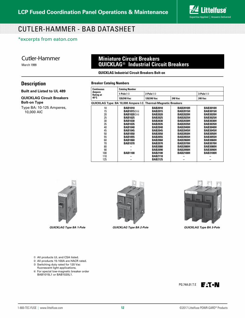
CUTLER-HAMMER - BAB DATASHEET*excerpts from eaton.com
March 1999
PG.74A.01.T.E
Cutler-Hammer Miniature Circuit BreakersQUICKLAG Industrial Circuit BreakersQUICKLAG Industrial Circuit Breakers Bolt-on
DescriptionBuilt and Listed to UL 489
QUICKLAG Circuit BreakersBolt-on TypeType BA: 10-125 Amperes,
10,000 AIC
QUICKLAG Type BA 1-Pole
QUICKLAG Type BA 3-PoleQUICKLAG Type BA 2-Pole
Breaker Catalog Numbers
ContinuousAmpereRating at 40°C
Catalog Number
1-Pole➀➁ 2-Pole➀➁ 3-Pole➀➁
120/240 Vac 120/240 Vac 240 Vac 240 Vac
QUICKLAG Type: BA 10,000 Ampere I.C. Thermal-Magnetic Breakers
10 15 20 25 30 35 40 45 50 55 60 70 80 90100110125
BAB1010BAB1015➂➃BAB1020➂➃BAB1025BAB1030BAB1035BAB1040BAB1045BAB1050BAB1055BAB1060BAB1070
––
BAB1100––
BAB2010BAB2015BAB2020BAB2025BAB2030BAB2035BAB2040BAB2045BAB2050BAB2055BAB2060BAB2070BAB2080BAB2090BAB2100BAB2110BAB2125
BAB2010HBAB2015HBAB2020HBAB2025HBAB2030HBAB2035HBAB2040HBAB2045HBAB2050HBAB2055HBAB2060HBAB2070HBAB2080HBAB2090HBAB2100H
––
BAB3010HBAB3015HBAB3020HBAB3025HBAB3030HBAB3035HBAB3040HBAB3045HBAB3050HBAB3055HBAB3060HBAB3070HBAB3080HBAB3090HBAB3100H
––
➀ All products UL and CSA listed.➁ All products 15-100A are HACR rated.➂ Switching duty rated for 120 Vac
fluorescent light applications.➃ For special low-magnetic breaker order
BAB1015L1 or BAB1020L1.

©2017 Littelfuse POWR-GARD® Products1-800-TEC-FUSE | www.littelfuse.com
LCP Fused Coordination Panel Operations & Maintenance
13
QUICKLAG 1-Pole Circuit Breakers, 10-70 Amperes
Curve No. SC-3500-77C
Maximum
Maximum Interrupting Time
(50-70 Amp)
(10-40 Amp)
Interrupting Rating (See Tabulation Above)
Circuit Breaker Time/Current Curves
QUICKLAG® 1-Pole Circuit Breakers, 10-70 Amperes
For application and coordination purposes only. Based on 40�Cambient, cold start. Connected with four (4) feet of rated wire (60/75�C)per terminal. Tested in open air with current in all poles.
Breaker Ratings (UL Listed)
Minimum
Special Low-MagneticType HQP, QC, BAB 15-20A
100
50
30
20
10
5
3
2
1
.5
.3
.2
.1
.05
.03
.02
.01
.005
.003
.002
.001
TIME IN
SECONDS
1,000
500
300
200
5,000
3,000
2,000
1 HOUR1 M
INUTE
2 HOURS
TIM
E IN
SEC
ONDS
10,000
100
50
30
20
10
5
3
2
1
.5
.3
.2
.1
.05
.03
.02
.01
.005
.003
.002
.001
1,000
500
300
200
5,000
3,000
2,000
1 HO
UR1
MIN
UTE
2 HO
URS
100
8060 907050 1000
800
600
900
700
500
400
300
200
10,0
00
8000
6000
9000
7000
5000
4000
3000
2000
100,
000
80,0
00
60,0
00
90,0
00
70,0
00
50,0
00
40,0
00
30,0
00
20,0
00
10,0
00
8000
6000
9000
7000
5000
4000
3000
2000
100080
0
600
900
700
500
400
300
200
1008060 907050
100,
000
80,0
00
60,0
00
90,0
00
70,0
00
50,0
00
40,0
00
30,0
00
20,0
00
CURRENT IN PERCENT OF BREAKER TRIP UNIT RATING
CURRENT IN PERCENT OF BREAKER TRIP UNIT RATING
10,000
BreakerType1-Pole
MaximumVoltsAc (60 Hz)
ContinuousAmperes
Interrupting CapacityRMS SymmetricalAmperes (kA)
HQP, QC, BABQCR, QCFQCGF, QCGFEP➂QBGF, QBGFEP➂QPGF, QPGFEP➂QPHW, QBHW, QCHWQCHGF, QCHGFEP➂QBHGF, QBHGFEP➂QPHGF, QPHGFEP➂QHPX, QHCX, HBAXQHPW, QHCW, HBAW
120/240120/240120/240120/240120/240120/240120/240120/240120/240120/240120/240
10-7010-6015-4015-4015-4015-7015-3015-3015-3015-7015-30
1010101010222222224265
Maximum Single-PoleTrip Times at 25 C➀
➀ Single-pole test data at 25 C based on NEMA proceduresfor verifying performance of molded case circuit breakers.
➁ For Special Low-Magnetic Types HQP, QC, BAB.➂ Time current curves show thermal-magnetic protection.
GF protection has 5ma trip sensitivity. GFEP protection has30ma trip sensitivity.
Continuous Amperes Instantaneous Trip Range, Amperes
10-2025-4045-607015-20➁
200-400300-500450-650800-1200125-225
CUTLER-HAMMER - BAB DATASHEET*excerpts from eaton.com

©2017 Littelfuse POWR-GARD® Products1-800-TEC-FUSE | www.littelfuse.com
LCP Fused Coordination Panel Operations & Maintenance
14
CUTLER-HAMMER - GHB DATASHEET*excerpts from eaton.com
March 1999
PG.74A.01.T.E
Cutler-Hammer Molded Case Circuit Breakers15-100 AmperesSeries C G-Frame
Instruction Leaflet/FRED Number 15547
Type GHB Thermal-Magnetic Circuit Breakers with Non-Interchangeable Trip Units➃
Continuous Ampere Rating@ 40°C
277/480 Vac Maximum, 125 Vdc Maximum➀
277/480 Vac Maximum, 125/250 Vdc Maximum
277/480 Vac Maximum, 125/250 Vdc Maximum➁
eloP-3eloP-2eloP-1
Catalog Number
152025303540455060708090
100
GHB1015➂GHB1020➂GHB1025GHB1030GHB1035GHB1040GHB1045GHB1050GHB1060GHB1070GHB1080GHB1090GHB1100
GHB2015➂GHB2020➂GHB2025GHB2030GHB2035GHB2040GHB2045GHB2050GHB2060GHB2070GHB2080GHB2090GHB2100
GHB3015➂GHB3020➂GHB3025GHB3030GHB3035GHB3040GHB3045GHB3050GHB3060GHB3070GHB3080GHB3090GHB3100
➀ 15 through 70 ampere circuit breakers only.➁ Use (2) outside poles.➂ Uses .190-32 screw type clamp terminals.➃ 480Y/277V, circuit breakers (Type GHB)
not suitable for 3-phase Delta (480V).
These breakers meet the require-ments of Federal Specification W-C-375b as follows:
Types GB, GHB, 120 and 240 Volts:1 Pole: Class 11a.2, 3 Poles: Classes 10b, 11b, 12b,14b, 15b
Type GHB, 277 and 480Y/277 Volts:1 Pole: Classes 12c, 13a2, 3 Poles: Class 13b
Type GB Thermal-Magnetic Circuit Breakers with Non-Interchangeable Trip Units
Continuous Ampere Rating@ 40°C
120 Vac Maximum, 125 Vdc Maximum➀
240 Vac Maximum, 125/250 Vdc Maximum
240 Vac Maximum, 125/250 Vdc Maximum➁
eloP-3eloP-2eloP-1
Catalog Number
152025303540455060708090
100
GB1015➂GB1020➂GB1025GB1030GB1035GB1040GB1045GB1050GB1060GB1070GB1080GB1090GB1100
GB2015➂GB2020➂GB2025GB2030GB2035GB2040GB2045GB2050GB2060GB2070GB2080GB2090GB2100
GB3015➂GB3020➂GB3025GB3030GB3035GB3040GB3045GB3050GB3060GB3070GB3080GB3090GB3100
Types GB and GHB Bolt-On Panelboard Circuit Breakers
Typical GB

©2017 Littelfuse POWR-GARD® Products1-800-TEC-FUSE | www.littelfuse.com
LCP Fused Coordination Panel Operations & Maintenance
15
CUTLER-HAMMER - GHB DATASHEET*excerpts from eaton.com
AB DE-ION Circuit Breakers
Curve No. SC-3500-83B
Ac Volts60 Hz
120277
Instantaneous Trip, Amperes
See Curve
Symmetrical RMS Amperes
120 Volts
65,00065,000
277 Volts
14,000
Maximum
Interrupting Rating (See Tabulation Above)
Circuit Breaker Time/Current Curves
G-Frame Circuit Breakers
Catalog Types GB, GC, 15-100 Amperes, 1 Pole, 120 Volts Ac Max.Catalog Types GHB, GHC, 15-100 Amperes, 1 Pole, 277 Volts AcMax.
For application and coordination purposes only. Based on 40°Cambient, cold start. Connected with four (4) feet of rated wire(60/75°C) per terminal. Tested in open air with current in all poles.
Maximum VoltsBreakerType
GB, GCGHB, GHC
Breaker RatingContinuous Amperes
15-100
Interrupting Rating (UL Listed)BreakerType
GB, GCGHB, GHC
Minimum
100
50
30
20
10
5
3
2
1
.5
.3
.2
.1
.05
.03
.02
.01
.005
.003
.002
.001
TIME IN
SECONDS
1,000
500
300
200
5,000
3,000
2,000
1 HOUR1 M
INUTE
2 HOURS
TIM
E IN
SEC
ONDS
10,000
100
50
30
20
10
5
3
2
1
.5
.3
.2
.1
.05
.03
.02
.01
.005
.003
.002
.001
1,000
500
300
200
5,000
3,000
2,000
1 HO
UR1
MIN
UTE
2 HO
URS
100
8060 907050 1000
800
600
900
700
500
400
300
200
10,0
00
8000
6000
9000
7000
5000
4000
3000
2000
100,
000
80,0
00
60,0
00
90,0
00
70,0
00
50,0
00
40,0
00
30,0
00
20,0
00
10,0
00
8000
6000
9000
7000
5000
4000
3000
2000
100080
0
600
900
700
500
400
300
200
1008060 907050
100,
000
80,0
00
60,0
00
90,0
00
70,0
00
50,0
00
40,0
00
30,0
00
20,0
00
Maximum Interrupting Time
CURRENT IN PERCENT OF BREAKER TRIP UNIT RATING
CURRENT IN PERCENT OF BREAKER TRIP UNIT RATING
10,000
Types GHB 15-100 Amperes, 1 PoleAB DE-ION Circuit Breakers
Curve No. SC-3501-83B
Ac Volts60 Hz
240277/480
Instantaneous Trip, Amperes
See Curve
Symmetrical RMS Amperes
240 Volts
65,00065,000
277/480 Volts
14,000
Maximum
Interrupting Rating (See Tabulation Above)
Minimum
Circuit Breaker Time/Current Curves
G-Frame Circuit Breakers
Catalog Types GB, GC, 15-100 Amperes, 2 and 3 Poles, 240 Volts AcMax.Catalog Types GHB, GHC, 15-100 Amperes, 2 and 3 Poles, 277/480Volts Ac Max.
For application and coordination purposes only. Based on 40°Cambient, cold start. Connected with four (4) feet of rated wire(60/75°C) per terminal. Tested in open air with current in all poles.
Maximum VoltsBreakerType
GB, GCGHB, GHC
Breaker RatingContinuous Amperes
15-100
Interrupting Rating (UL Listed)BreakerType
GB, GCGHB, GHC
100
50
30
20
10
5
3
2
1
.5
.3
.2
.1
.05
.03
.02
.01
.005
.003
.002
.001
TIME IN
SECONDS
1,000
500
300
200
5,000
3,000
2,000
1 HOUR1 M
INUTE
2 HOURS
TIM
E IN
SEC
ONDS
10,000
100
50
30
20
10
5
3
2
1
.5
.3
.2
.1
.05
.03
.02
.01
.005
.003
.002
.001
1,000
500
300
200
5,000
3,000
2,000
1 HO
UR1
MIN
UTE
2 HO
URS
100
8060 907050 1000
800
600
900
700
500
400
300
200
10,0
00
8000
6000
9000
7000
5000
4000
3000
2000
100,
000
80,0
00
60,0
00
90,0
00
70,0
00
50,0
00
40,0
00
30,0
00
20,0
00
10,0
00
8000
6000
9000
7000
5000
4000
3000
2000
100080
0
600
900
700
500
400
300
200
1008060 907050
100,
000
80,0
00
60,0
00
90,0
00
70,0
00
50,0
00
40,0
00
30,0
00
20,0
00
Maximum Interrupting Time
CURRENT IN PERCENT OF BREAKER TRIP UNIT RATING
CURRENT IN PERCENT OF BREAKER TRIP UNIT RATING
10,000
Types GB, GHB, GC, GHC 15-100 Amperes, 2 and 3 Poles

©2017 Littelfuse POWR-GARD® Products1-800-TEC-FUSE | www.littelfuse.com
LCP Fused Coordination Panel Operations & Maintenance
16
RECOMMENDED MAINTENANCE
• The product should not be in an environments greater than 75 degrees Celsius.
• If the ambient temperature drastically changes, inspect the exterior of the panel and ensure the fuses and breakers are still working correctly.
• Occasionally clean by removing dust and other collective particles that may accumulate.
• Ensure all the fuses are still operational, which can be easily done by looking for the red LED light on the fuseholder. If it is on, it means the fuse has opened and needs to be replaced. In most cases it will be fairly obvious if a breaker has tripped or fuse has opened because that particular circuit would be opened.
• Periodically inspect the panel exterior to ensure the NEMA-Rated enclosure is properly protecting the panel product from the elements.
• An annual review of the panel is recommended to make sure the holders haven’t loosened and the breakers are still tightly affixed.

©2017 Littelfuse POWR-GARD® Products1-800-TEC-FUSE | www.littelfuse.com
LCP Fused Coordination Panel Operations & Maintenance
17
FREQUENTLY ASKED QUESTIONS
1. Part of my panel was shipped during transit? What should I do?Please have your distributor contact Littelfuse customer service. Take pictures if possible to help Littelfuse file a claim with the courier.
2. How can I change circuit’s amperage??If the desired amperage is less than 30A moving to an amperage less than 30A (or, the desired amperage is greater than 30A moving to an amperage greater than 30A), this is can be replaced in the field by a certified electrician. Order a new breaker from Eaton (see pg. 11 & 13 of this document for reference) and a new fuse from Littelfuse (see pg. 5 & 8 of this document for reference).
If changing the circuit from an amperage less than 30A to an amperage greater than 30A (or vice versa), a new panel lining needs to be constructed and assembly instructions will be sent for field replacement by a certified electrician. Please contact Littelfuse customer service if this is the scenario.
3. I realized that I need a flush mount panel after I received it? How can I switch from a surface to a flush?
• This is not a complicated modification. Contact Littelfuse Customer Service to receive a new flush cover with assembly instructions that can be installed in the field by a certified electrician.
4. How can I get some extra circuit identifiers for the panel?Contact Littelfuse customer service
5. Can I replace the Littelfuse fuse with another manufacturer’s fuse?While Littelfuse would always prefer you use Littelfuse fuses for both your business and to keep the product solely Littelfuse for a single point of contact, it understands that sometimes you need a quick replacement and might not have a Littelfuse option. Yes, you can use any manufacturers’ fuse that is UL-Listed to the same classification as the original Littelfuse product.
6. For some reason there is a different manufacturers’ fuse in your coordination panel. How can I cross it over to the Littelfuse product?Call the Littelfuse TEC-LINE for a simple cross, or visit www.littelfuse.com for a simple cross reference tool.
7. What style circuit breakers do you use on branch circuits? I need a replacement.• For 120/208V panels, Eaton BAB style breakers
• For 277/480V panels, Eaton GHB style breakers
• If you’re referring to a breaker beyond 60A, please contact Littelfuse customer service. There is a variety of breaker styles chosen from based on specific application requirements. The breakers used on every panel are highlighted on the technical drawings that the specifying engineer signed off on before the job was released, so that is another source for you to reference if that file is still in your possession.
8. Why can’t I use Square D breakers as replacements?These coordination panels were designed and built specifically with Eaton-style breakers. To protect UL and ensure the product works correctly, you should use Eaton breakers only for replacement.
9. What if I want to order a new coordination panel from you but only want to use Square D breakers?Please, e-mail [email protected] to discuss this request

©2017 Littelfuse POWR-GARD® Products1-800-TEC-FUSE | www.littelfuse.com
LCP Fused Coordination Panel Operations & Maintenance
18
FREQUENTLY ASKED QUESTIONS
10. My fuse keeps opening on one of my circuits. Should I increase the amperage?No, the fuse is opening for a reason and because it’s the fuse as opposed to the breaker, there’s a good chance that the fuse is preventing short circuit damage, which is especially dangerous and potentially fatal.
Before you change fuse amperage, you should understand why the fuse is opening. Simply increasing the fuse amperage puts expensive equipment and people’s safety at risk.
11. I need to change my feed-through lugs to sub-feed lugs. How can I do this?Please contact Littelfuse customer service. This is a relatively challenging modification if the panel has already been installed. If it has not yet been installed, it still requires assembly instructions and a new set of lugs.
12. A breaker on one of my circuits keeps tripping. Any idea why?You can use which device is opening within the coordination panel to give a plausible explanation as to the cause. If the breaker is opening, it’s likely due to an overload of that circuit. If the fuse opens, it’s likely preventing due to a short circuit.
13. I’d like to sub-feed my panel post-installation to another device. How can I do that?Please e-mail [email protected]. This may be a simple modification, depending on the specifics surrounding the application, but it could vary greatly by what device you’re feeding, how far away it is, and what types of loads it’s required to sustain.
14. Are there any technical concerns with replacing my main fuse pullout with main lugs to feed through to an upstream breaker?
The main fuse pullout is most likely the main device because it was needed to achieve selective coordination with the upstream breaker. Before you look to modify anything, consult the building’s one-line drawings to ensure what the upstream device is. If it is a circuit breaker, you should not modify the coordination panel. Doing so may violate UL and would remove the selective coordination. Please contact Littelfuse Technical Support to discuss your situation.
15. Is there any way to increase the branch breakers’ SCCR?There is not a way to physically change the device’s SCCR (10kAIC for BAB breakers & 14kAIC for GHB breakers). But if you feed the branch circuit to a fused disconnect switch instead of a breaker you can use the upstream coordination to protect the circuit.
16. I’d like to add a spare fuse cabinet so I can keep replacements inside the panel. How can I do this?
Contact Littelfuse customer service. There are multiple ways to accomplish this, such as a contraption that you can screw into the door assembly similar to the picture below. To find the best option call customer service.
©2017 Littelfuse POWR-GARD® Products1-800-TEC-FUSE | www.littelfuse.com
LCP Fused Coordination Panel Operations & Maintenance
19
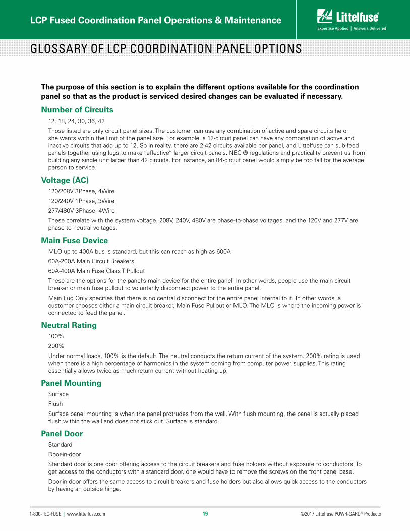
GLOSSARY OF LCP COORDINATION PANEL OPTIONS
The purpose of this section is to explain the different options available for the coordination panel so that as the product is serviced desired changes can be evaluated if necessary.
Number of Circuits12, 18, 24, 30, 36, 42
Those listed are only circuit panel sizes. The customer can use any combination of active and spare circuits he or she wants within the limit of the panel size. For example, a 12-circuit panel can have any combination of active and inactive circuits that add up to 12. So in reality, there are 2-42 circuits available per panel, and Littelfuse can sub-feed panels together using lugs to make “effective” larger circuit panels. NEC ® regulations and practicality prevent us from building any single unit larger than 42 circuits. For instance, an 84-circuit panel would simply be too tall for the average person to service.
Voltage (AC)120/208V 3Phase, 4Wire
120/240V 1Phase, 3Wire
277/480V 3Phase, 4Wire
These correlate with the system voltage. 208V, 240V, 480V are phase-to-phase voltages, and the 120V and 277V are phase-to-neutral voltages.
Main Fuse DeviceMLO up to 400A bus is standard, but this can reach as high as 600A
60A-200A Main Circuit Breakers
60A-400A Main Fuse Class T Pullout
These are the options for the panel’s main device for the entire panel. In other words, people use the main circuit breaker or main fuse pullout to voluntarily disconnect power to the entire panel.
Main Lug Only specifies that there is no central disconnect for the entire panel internal to it. In other words, a customer chooses either a main circuit breaker, Main Fuse Pullout or MLO. The MLO is where the incoming power is connected to feed the panel.
Neutral Rating100%
200%
Under normal loads, 100% is the default. The neutral conducts the return current of the system. 200% rating is used when there is a high percentage of harmonics in the system coming from computer power supplies. This rating essentially allows twice as much return current without heating up.
Panel MountingSurface
Flush
Surface panel mounting is when the panel protrudes from the wall. With flush mounting, the panel is actually placed flush within the wall and does not stick out. Surface is standard.
Panel DoorStandard
Door-in-door
Standard door is one door offering access to the circuit breakers and fuse holders without exposure to conductors. To get access to the conductors with a standard door, one would have to remove the screws on the front panel base.
Door-in-door offers the same access to circuit breakers and fuse holders but also allows quick access to the conductors by having an outside hinge.

©2017 Littelfuse POWR-GARD® Products1-800-TEC-FUSE | www.littelfuse.com
LCP Fused Coordination Panel Operations & Maintenance
20
Fuse Holders30A Class CC LPSC Holders
60A Class J LFPSJ Holders
Up to 30A, the LPSC is standard. From 30A – 60A the LFPSJ holder is standard
Feeder Circuit Breakers1 Pole: 10A-60A
2 Pole: 10A-60A
3 Pole: 10A-60A
Standard applications call for single pole circuit breakers. Two and three pole breakers allow for other options, which include motors. For each of the options, we offer between a 10 and 60 amp breaker.
If the application calls for something above 60A, a breaker is available, but it cannot be fused. Alternatively, a branch-circuit Class T pullout can be used to ensure coordination
Panel FeedTop
Bottom
Top means the feeder conductors are connected through the top, and the bottom means they come in underneath.
Panel LugsNone
Sub-feed (MLO)
Feed-through
These lugs allow two panels to be connected to one another. If the customer wanted to “daisy chain” a number of panels, he/she would need these lugs.
Enclosure RatingNEMA 1
NEMA 3R
NEMA 4X
NEMA 1 is standard. NEMA 3R is for outside applications. The door is sealed to prevent moisture from leaking in, etc. NEMA 4X is especially preventative against corrosion and is both water- and dust-tight.
If you have any questions, refer to the Frequently Asked Questions in this document. If you still have questions about the panel options or anything else regarding the Littelfuse LCP Coordination Panel, please e-mail [email protected]
GLOSSARY OF LCP COORDINATION PANEL OPTIONS
Rev: 053117