LCD Monitor - sonypro.vnsonypro.vn/Content/File/Catalog LMD-2735MD2435MD...This unit has no power...
33
4-584-947-11(1) LCD Monitor Instructions for Use Before operating the unit, please read this manual thoroughly and retain it for future reference. LMD-2735MD LMD-2435MD © 2016 Sony Corporation 2016-03
Transcript of LCD Monitor - sonypro.vnsonypro.vn/Content/File/Catalog LMD-2735MD2435MD...This unit has no power...

4-584-947-11(1)2016-03
LCD Monitor
Instructions for UseBefore operating the unit, please read this manual thoroughly and retain it for future reference.
LMD-2735MDLMD-2435MD
© 2016 Sony Corporation
2
Indications for Use/Intended Use
The Sony LMD-2735MD/2435MD LCD Monitor are intended to provide 2D color video displays of images from surgical endoscopic/laparoscopic camera systems and other compatible medical imaging systems.The LMD-2735MD/2435MD monitor are a widescreen, high-definition, medical grade monitor for real-time use during minimally invasive surgical procedures and are suitable for use in hospital operating rooms, surgical centers, clinics, doctors’ offices and similar medical environments.
WARNING
To reduce the risk of fire or electric shock, do not expose this apparatus to rain or moisture.
To avoid electrical shock, do not open the cabinet. Refer servicing to qualified personnel only.
No modification of this equipment is allowed.
WARNING
To avoid the risk of electric shock, this equipment must only be connected to a supply mains with protective earth.
WarningThis unit has no power switch.To disconnect the main power, unplug the power plug.When installing the unit, incorporate a readily accessible disconnect device in the fixed wiring, or connect the power plug to an easily accessible socket-outlet near the unit.Do not position the ME equipment where it is difficult to unplug the power plug.If a fault should occur during operation of the unit, operate the disconnect device to switch the power supply off, or unplug the power plug.
For the customers in the U.S.A.This equipment has been tested and found to comply with the limits for a Class A digital device, pursuant to part 15 of the FCC Rules. These limits are designed to provide reasonable protection against harmful interference when the equipment is operated in a commercial environment. This equipment generates, uses and can radiate radio frequency energy and, if not installed and used in accordance with the instruction manual, may cause harmful interference to radio communications. Operation of this equipment in a residential area is likely to cause harmful interference in which case the user will be required to correct the interference at his own expense.
You are cautioned that any changes or modifications not expressly approved in this manual could void your authority to operate this equipment.
All interface cables used to connect peripherals must be shielded in order to comply with the limits for a digital device pursuant to Subpart B of part 15 of FCC Rules.
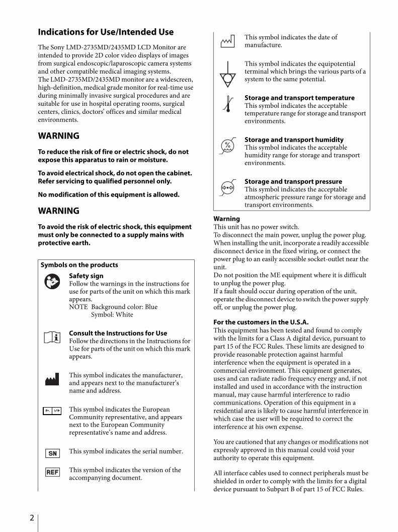
Symbols on the products
Safety signFollow the warnings in the instructions for use for parts of the unit on which this mark appears.NOTE Background color: Blue
Symbol: White
Consult the Instructions for UseFollow the directions in the Instructions for Use for parts of the unit on which this mark appears.
This symbol indicates the manufacturer, and appears next to the manufacturer’s name and address.
This symbol indicates the European Community representative, and appears next to the European Community representative’s name and address.
This symbol indicates the serial number.
This symbol indicates the version of the accompanying document.
This symbol indicates the date of manufacture.
This symbol indicates the equipotential terminal which brings the various parts of a system to the same potential.
Storage and transport temperatureThis symbol indicates the acceptable temperature range for storage and transport environments.
Storage and transport humidityThis symbol indicates the acceptable humidity range for storage and transport environments.
Storage and transport pressureThis symbol indicates the acceptable atmospheric pressure range for storage and transport environments.
This device complies with part 15 of the FCC Rules. Operation is subject to the following two conditions: (1) This device may not cause harmful interference, and (2) this device must accept any interference received, including interference that may cause undesired operation.
For the customers in CanadaCAN ICES-3 (A)/NMB-3(A)
This unit has been certified according to Standard CAN/CSA-C22.2 No.60601-1.
Important safeguards/notices for use in the medical environments1. All the equipments connected to this unit shall be
certified according to Standard IEC 60601-1, IEC 60950-1, IEC 60065 or other IEC/ISO Standards applicable to the equipments.
2. Furthermore all configurations shall comply with the system standard IEC 60601-1. Everybody who connects additional equipment to the signal input part or signal output part configures a medical system, and is therefore, responsible that the system
complies with the requirements of the system standard IEC 60601-1.If in doubt, consult the qualified service personnel.
3. The leakage current could increase when connected to other equipment.
4. For this particular equipment, all accessory equipment connected as noted above, must be connected to mains via an additional isolation transformer conforming with the construction requirements of IEC 60601-1 and providing at least Basic Insulation.
5. This equipment generates, uses, and can radiate radio frequency energy. If it is not installed and used in accordance with the instruction manual, it may cause interference to other equipment. If this unit causes interference (which can be determined by unplugging the power cord from the unit), try these measures: Relocate the unit with respect to the susceptible equipment. Plug this unit and the susceptible equipment into different branch circuit.
Consult your dealer. (According to standard IEC 60601-1-2 and CISPR11, Class B, Group 1)
Important EMC notices for use in the medical environments The LMD-2735MD/2435MD needs special precautions regarding EMC and needs to be installed and put into service
according to the EMC information provided in the instructions for use. The portable and mobile RF communications equipment such as cellular phones can affect the LMD-2735MD/
2435MD.
WarningThe use of accessories and cables other than those specified, with the exception of replacement parts sold by Sony Corporation, may result in increased emissions or decreased immunity of the LMD-2735MD/2435MD.
WarningIf the LMD-2735MD/2435MD should be used adjacent to or stacked with other equipment, it should be observed to verify normal operation in the configuration in which it will be used.
Guidance and manufacturer’s declaration-electromagnetic emissions
The LMD-2735MD/2435MD is intended for use in the electromagnetic environment specified below.The customer or the user of the LMD-2735MD/2435MD should assure that it is used in such an environment.
Emission test Compliance Electromagnetic environment-guidanceRF emissions
CISPR 11 Group 1The LMD-2735MD/2435MD uses RF energy only for its internal function. Therefore, its RF emissions are very low and are not likely to cause any interference in nearby electronic equipment.
RF emissions
CISPR 11Class B
The LMD-2735MD/2435MD is suitable for use in all establishments, including domestic establishments and those directly connected to the public low-voltage power supply network that supplies buildings used for domestic purposes.Harmonic emissions
IEC 61000-3-2
Class D (AC input)
Not applicable (DC input)Voltage fluctuations/flicker emissions
IEC 61000-3-3
Complies (AC input)
Not applicable (DC input)
3

4
Guidance and manufacturer’s declaration - electromagnetic immunity
The LMD-2735MD/2435MD is intended for use in the electromagnetic environment specified below. The customer or the user of the LMD-2735MD/2435MD should assure that it is used in such as environment.
Immunity test IEC 60601 test levelCompliance level
Electromagnetic environment-guidanceAC input DC input
Electrostatic discharge (ESD)
IEC 61000-4-2
±6 kV contact
±8 kV air
±6 kV contact
±8 kV air
±6 kV contact
±8 kV air
Floors should be wood, concrete or ceramic tile. If floors are covered with synthetic material, the relative humidity should be at least 30%.
Electrical fast transient/burst
IEC 61000-4-4
±2 kV for power supply lines
±1 kV for input/output lines
±2 kV for power supply lines
±1 kV for input/output lines
±1 kV for input/output lines
Mains power quality should be that of a typical commercial or hospital environment.
Surge
IEC 61000-4-5
±1 kV line(s) to line(s)
±2 kV line(s) to earth
±1 kV differential mode
±2 kV common mode
Not applicable Mains power quality should be that of a typical commercial or hospital environment.
Voltage dips, short interruptions and voltage variations on power supply input lines
IEC 61000-4-11
< 5% (> 95% dip in ) for 0.5 cycle
40% (60% dip in ) for 5 cycles
70% (30% dip in ) for 25 cycles
< 5% (> 95% dip in ) for 5 sec
< 5% (> 95% dip in ) for 0.5 cycle
40% (60% dip in ) for 5 cycles
70% (30% dip in ) for 25 cycles
< 5% (> 95% dip in ) for 5 sec
Not applicable Mains power quality should be that of a typical commercial or hospital environment. If the user of the LMD-2735MD/2435MD requires continued operation during power mains interruptions, it is recommended that the LMD-2735MD/2435MD be powered from an uninterruptible power supply or a battery.
Power frequency (50/60 Hz) magnetic field
IEC 61000-4-8
3 A/m 3 A/m 3 A/m Power frequency magnetic fields should be at levels characteristic of a typical location in a typical commercial or hospital environment.
NOTE: is the a.c. mains voltage prior to application of the test level.

Guidance and manufacturer’s declaration - electromagnetic immunity
The LMD-2735MD/2435MD is intended for use in the electromagnetic environment specified below. The customer or the user of the LMD-2735MD/2435MD should assure that it is used in such as environment.
Immunity test IEC 60601 test level Compliance level Electromagnetic environment-guidance
Conducted RF
IEC 61000-4-6
Radiated RF
IEC 61000-4-3
3 Vrms
150 kHz to 80 MHz
3 V/m
80 MHz to 2.5 GHz
3 Vrms
3 V/m
Portable and mobile RF communications equipment should be used no closer to any part of the LMD-2735MD/2435MD, including cables, than the recommended separation distance calculated from the equation appliance to the frequency of the transmitter.
Recommended separation distance
d = 1.2
d = 1.2 80 MHz to 800 MHz
d = 2.3 800 MHz to 2.5 GHz
Where P is the maximum output power rating of the transmitter in watts (W) according to the transmitter manufacturer and d is the recommended separation distance in meters (m).
Field strengths from fixed RF transmitters, as determined by an electromagnetic site survey, a should be less than the compliance level in each frequency range. b
Interference may occur in the vicinity of equipment marked with following symbol:
NOTE 1: At 80 MHz and 800 MHz, the higher frequency range applies.
NOTE 2: These guidelines may not apply in all situations. Electromagnetic propagation is affected by absorption and reflection from structures, objects and people.
a Field strengths from fixed transmitters, such as base stations for radio (cellular/cordless) telephones and land mobile radios, amateur radio, AM and FM radio broadcast and TV broadcast cannot be predicted theoretically with accuracy. To assess the electromagnetic environment due to fixed RF transmitters, an electromagnetic site survey should be considered. If the measured field strength in the location in which the LMD-2735MD/2435MD is used exceeds the applicable RF compliance level above, the LMD-2735MD/2435MD should be observed to verify normal operation. If abnormal performance is observed, additional measures may be necessary, such as reorienting or relocating the LMD-2735MD/2435MD.
b Over the frequency range 150 kHz to 80 MHz, field strengths should be less than 3 V/m.
5
6
CautionWhen you dispose of the unit or accessories, you must obey the laws in the relative area or country and the regulations in the relative hospital regarding environmental pollution.
Warning on power connectionUse a proper power cord for your local power supply.1. Use the approved Power Cord (3-core mains lead) /
Appliance Connector / Plug with earthing-contacts that conforms to the safety regulations of each country if applicable.
2. Use the Power Cord (3-core mains lead) / Appliance Connector / Plug conforming to the proper ratings (Voltage, Ampere).If you have questions on the use of the above Power Cord / Appliance Connector / Plug, please consult a qualified service personnel.
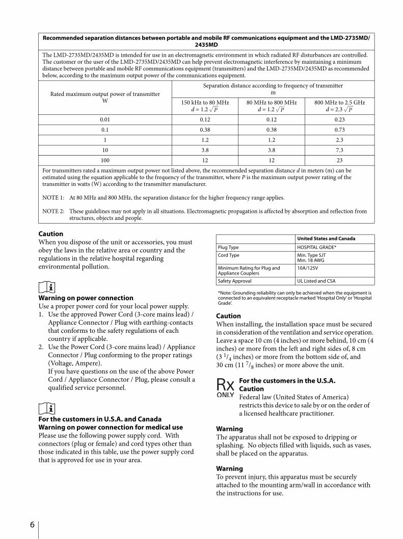
For the customers in U.S.A. and CanadaWarning on power connection for medical usePlease use the following power supply cord. With connectors (plug or female) and cord types other than those indicated in this table, use the power supply cord that is approved for use in your area.
*Note: Grounding reliability can only be achieved when the equipment is connected to an equivalent receptacle marked 'Hospital Only' or 'Hospital Grade'.
CautionWhen installing, the installation space must be secured in consideration of the ventilation and service operation. Leave a space 10 cm (4 inches) or more behind, 10 cm (4 inches) or more from the left and right sides of, 8 cm (3 1/4 inches) or more from the bottom side of, and 30 cm (11 7/8 inches) or more above the unit.
WarningThe apparatus shall not be exposed to dripping or splashing. No objects filled with liquids, such as vases, shall be placed on the apparatus.
WarningTo prevent injury, this apparatus must be securely attached to the mounting arm/wall in accordance with the instructions for use.
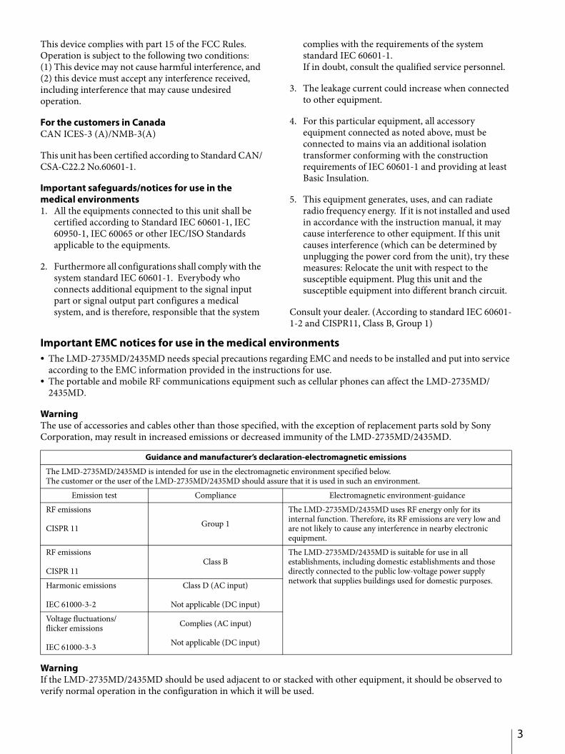
Recommended separation distances between portable and mobile RF communications equipment and the LMD-2735MD/2435MD
The LMD-2735MD/2435MD is intended for use in an electromagnetic environment in which radiated RF disturbances are controlled. The customer or the user of the LMD-2735MD/2435MD can help prevent electromagnetic interference by maintaining a minimum distance between portable and mobile RF communications equipment (transmitters) and the LMD-2735MD/2435MD as recommended below, according to the maximum output power of the communications equipment.
Rated maximum output power of transmitterW
Separation distance according to frequency of transmitterm
150 kHz to 80 MHzd = 1.2
80 MHz to 800 MHzd = 1.2
800 MHz to 2.5 GHzd = 2.3
0.01 0.12 0.12 0.230.1 0.38 0.38 0.731 1.2 1.2 2.3
10 3.8 3.8 7.3100 12 12 23
For transmitters rated a maximum output power not listed above, the recommended separation distance d in meters (m) can be estimated using the equation applicable to the frequency of the transmitter, where P is the maximum output power rating of the transmitter in watts (W) according to the transmitter manufacturer.
NOTE 1: At 80 MHz and 800 MHz, the separation distance for the higher frequency range applies.
NOTE 2: These guidelines may not apply in all situations. Electromagnetic propagation is affected by absorption and reflection from structures, objects and people.
United States and Canada
Plug Type HOSPITAL GRADE*
Cord Type Min. Type SJTMin. 18 AWG
Minimum Rating for Plug and Appliance Couplers
10A/125V
Safety Approval UL Listed and CSA
For the customers in the U.S.A. CautionFederal law (United States of America) restricts this device to sale by or on the order of a licensed healthcare practitioner.
Consult with Sony qualified personnel for mounting arm/wall mount installation.
For the customers in the U.S.A.SONY LIMITED WARRANTY - Please visit http://www.sony.com/psa/warranty for important information and complete terms and conditions of Sony’s limited warranty applicable to this product.
For the customers in CanadaSONY LIMITED WARRANTY - Please visit http://www.sonybiz.ca/pro/lang/en/ca/article/resources-warranty-product-registration for important information and complete terms and conditions of Sony’s limited warranty applicable to this product.
For the customers in EuropeSony Professional Solutions Europe - Standard Warranty and Exceptions on Standard Warranty.Please visit http://www.pro.sony.eu/warranty for important information and complete terms and conditions.
For the customers in KoreaSONY LIMITED WARRANTY - Please visit http://bpeng.sony.co.kr/handler/BPAS-Start for important information and complete terms and conditions of Sony’s limited warranty applicable to this product.
7
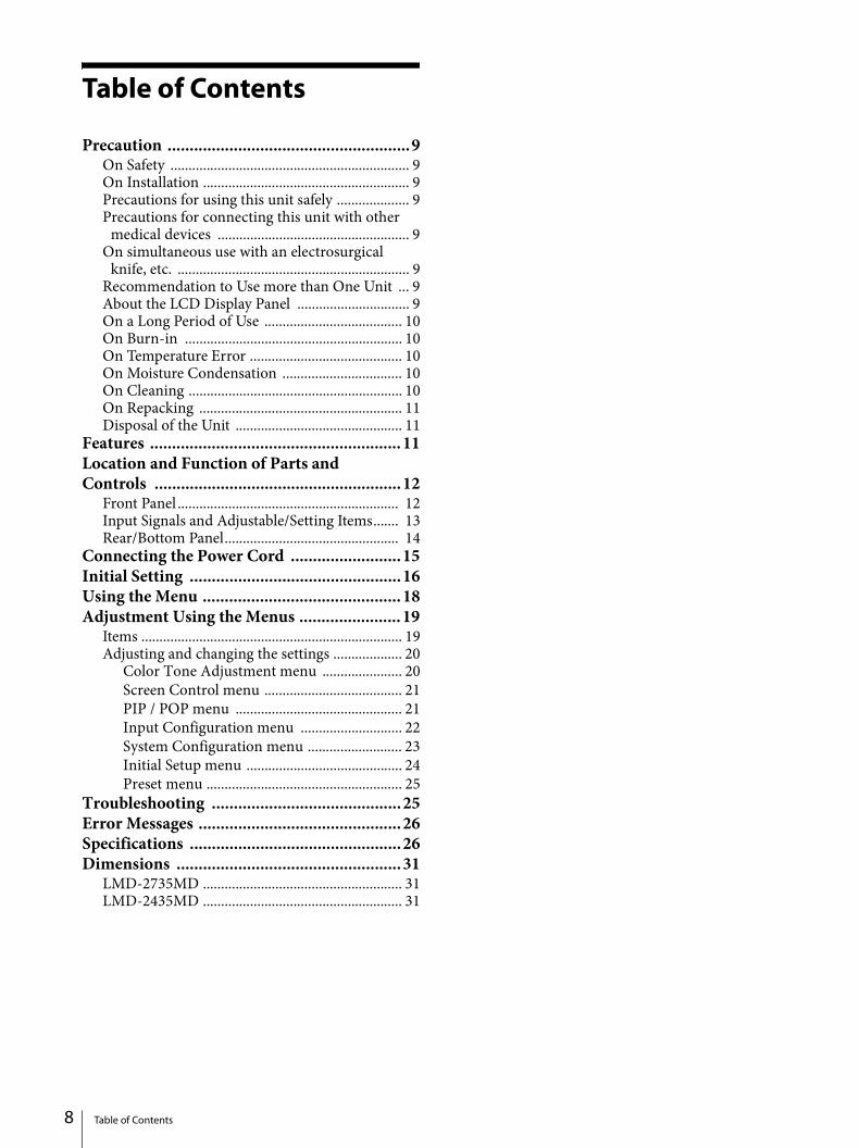
Table of Contents 8
Table of Contents
Precaution .......................................................9On Safety .................................................................. 9On Installation ......................................................... 9Precautions for using this unit safely .................... 9Precautions for connecting this unit with other
medical devices ..................................................... 9On simultaneous use with an electrosurgical
knife, etc. ................................................................ 9Recommendation to Use more than One Unit ... 9About the LCD Display Panel ............................... 9On a Long Period of Use ...................................... 10On Burn-in ............................................................ 10On Temperature Error .......................................... 10On Moisture Condensation ................................. 10On Cleaning ........................................................... 10On Repacking ........................................................ 11Disposal of the Unit .............................................. 11
Features .........................................................11Location and Function of Parts and Controls ........................................................12
Front Panel ............................................................. 12Input Signals and Adjustable/Setting Items....... 13Rear/Bottom Panel................................................ 14
Connecting the Power Cord .........................15Initial Setting ................................................16Using the Menu .............................................18Adjustment Using the Menus .......................19
Items ........................................................................ 19Adjusting and changing the settings ................... 20
Color Tone Adjustment menu ...................... 20Screen Control menu ...................................... 21PIP / POP menu .............................................. 21Input Configuration menu ............................ 22System Configuration menu .......................... 23Initial Setup menu ........................................... 24Preset menu ...................................................... 25
Troubleshooting ...........................................25Error Messages ..............................................26Specifications ................................................26Dimensions ...................................................31
LMD-2735MD ....................................................... 31LMD-2435MD ....................................................... 31

Precaution
On Safety
Operate the unit only with a power source as specified in the “Specifications” section.
The nameplate indicating operating voltage, etc. is located on the rear panel of monitor and the AC adaptor.
Should any solid object or liquid fall into the cabinet, unplug the unit and have it checked by qualified personnel before operating it any further.
Unplug the unit from the wall outlet if it is not to be used for several days or more.
To disconnect the AC power cord, pull it out by grasping the plug. Never pull the cord itself.
The socket-outlet shall be installed near the equipment and shall be easily accessible.
On Installation
Prevent internal heat build-up allowing adequate air circulation.Do not place the unit on surfaces (rugs, blankets, etc.) or near materials (curtains, draperies) that may block the ventilation holes.
Do not install the unit near heat sources such as radiators or air ducts, or in a place subject to direct sunlight, excessive dust, mechanical vibration or shock.
Do not place the monitor near equipment which generates magnetism, such as a transformer or high voltage power lines.
Precautions for using this unit safely
Some people may experience discomfort (such as eye strain, fatigue, or nausea) while watching video images. Sony recommends that all viewers take regular breaks while watching video images. The length and frequency of necessary breaks will vary from person to person. You must decide what works best. If you experience any discomfort, you should stop watching the video images until the discomfort ends; consult a doctor if you believe necessary.
Avoid watching the display in environments where your head may shake, or while you are walking or performing exercise, because there is a higher possibility that you experience discomfort.
Precautions for connecting this unit with other medical devices
Before you utilize this device and/or connect this device to any other medical device, please be aware of and abide by the following precautions:(a) Before actually using this device for medical practice, please check and confirm that you do not experience any discomfort in your use that could be disruptive or impeditive in conducting your intended activity or medical practice.(b) If you experience or are likely to experience such discomfort, please refrain from using this device.(c) Generally, discomfort (such as eye strain, fatigue, nausea, or motion sickness) can be provoked by such factors as quick movements or shakiness of video picture, focal position of video pictures, distance between objects and image capturing modules, user’s point of gaze in video pictures, other varying conditions of video pictures to be input to this device, and individual user’s health conditions.
Before you utilize this unit, check if the image of the connected medical device is displayed properly on the screen of this unit.
On simultaneous use with an electrosurgical knife, etc.
If this unit is used together with an electrosurgical knife, etc., the picture may be disturbed, warped or otherwise abnormal as a result of strong radio waves or voltages from the device. This is not a malfunction.When you use this unit simultaneously with a device from which strong radio waves or voltages are emitted, confirm the effect of this before using such devices, and install this unit in a way that minimizes the effect of radio wave interference.
Recommendation to Use more than One Unit
As problems can occasionally occur for the monitor, when the monitor is used for safety control of personnel, assets or stable picture, or for emergencies, we strongly recommend you use more than one unit or prepare a spare unit.
About the LCD Display Panel
The LCD panel fitted to this unit is manufactured with high precision technology, giving a functioning pixel ratio of at least 99.99%. Thus a very small proportion
Precaution 9
10
of pixels may be “stuck”, either always off (black), always on (red, green, or blue), or flashing. In addition, over a long period of use, because of the physical characteristics of the liquid crystal display, such “stuck” pixels may appear spontaneously. These problems are not a malfunction.
Do not leave the LCD screen facing the sun as it can damage the LCD screen. Take care when you place the unit by a window.
Do not push or scratch the LCD screen. Do not place a heavy object on the LCD screen. This may cause the screen to lose uniformity.
If the unit is used in a cold place, a residual image may appear on the screen. This is not a malfunction. When the monitor becomes warm, the screen returns to normal.
The screen and the cabinet become warm during operation. This is not a malfunction.
On a Long Period of Use
Due to the characteristics of LCD panel, displaying static images for extended periods, or using the unit repeatedly in a high temperature/high humidity environments may cause image smearing, burn-in, areas of which brightness is permanently changed, lines, or a decrease in overall brightness.
In particular, continued display of an image smaller than the monitor screen, such as in a different aspect ratio, may shorten the life of the unit. Avoid displaying a still image for an extended period, or using the unit repeatedly in a high temperature/high humidity environment such an airtight room, or around the outlet of an air conditioner.
To prevent any of the above issues, we recommend reducing brightness slightly, and to turn off the power whenever the unit is not in use.
On Burn-in
For LCD panel, permanent burn-in may occur if still images are displayed in the same position on the screen continuously, or repeatedly over extended periods.
Images that may cause burn-in Masked images with aspect ratios other than 16:9 Color bars or images that remain static for a long time Character or message displays that indicate settings or
the operating state
To reduce the risk of burn-in Turn off the character displays
Press the MENU button to turn off the character displays. To turn off the character displays of the connected equipment, operate the connected equipment accordingly. For details, refer to the operation manual of the connected equipment.
Turn off the power when not in useTurn off the power if the monitor is not to be used for a prolonged period of time.
On Temperature Error
When this unit is used in a high temperature environment and the internal temperature rises, a temperature error is displayed on the screen. When the temperature error is displayed, contact an authorized Sony dealer.
On Moisture Condensation
If the unit is suddenly taken from a cold to a warm location, or if ambient temperature suddenly rises, moisture may form on the outer surface of the unit and/or inside of the unit. This is known as condensation. If condensation occurs, turn off the unit and wait until the condensation clears before operating the unit. Operating the unit while condensation is present may damage the unit.
On Cleaning
Before cleaningBe sure to disconnect the AC power cord from the AC outlet.
On cleaning the monitorA material that withstands disinfection is used for the front protection plate of the medical use LCD monitor. The protection plate surface is specially treated to reduce reflection of light. When solvents such as benzene or thinner, or acid, alkaline or abrasive detergent, or chemical cleaning cloth are used for the protection plate surface/monitor surface, the performance of the monitor may be impaired or the finish of the surface may be damaged. Take care with respect to the following: Clean the protection plate surface/monitor surface
with a 50 to 70 v/v% concentration of isopropyl alcohol or a 76.9 to 81.4 v/v% concentration of ethanol using a swab method. Wipe the protection plate surface gently (wipe using less than 1 N force).
Stubborn stains may be removed with a soft cloth such as a cleaning cloth lightly dampened with mild detergent solution using a swab method and then clean using the above chemical solution.
Precaution
Never use solvents such as benzene or thinner, or acid, alkaline or abrasive detergent, or chemical cleaning cloth for cleaning or disinfection, as they will damage the protection plate surface/monitor surface.
Do not use unnecessary force to rub the protection plate surface/monitor surface with a stained cloth. The protection plate surface/monitor surface may be scratched.
Do not keep the protection plate surface/monitor surface in contact with a rubber or vinyl resin product for a long period of time. The finish of the surface may deteriorate or the coating may come off.
On Repacking
Do not throw away the carton and packing materials. They make an ideal container which to transport the unit.If you have any questions about this unit, contact your authorized Sony dealer.
Disposal of the Unit
Do not dispose of the unit with general waste.Do not include the monitor with household waste.
Features
Compliance with medical safety standards in U.S.A., Canada and EuropeIEC 60601-1 and product safety standards in the U.S.A., Canada and Europe have been obtained for this monitor.The monitor is designed for use in the medical treatment field, with the sheet switch, screen protect panel, etc.
High-resolution Full HD panelA Full HD high-resolution (1920 × 1080) panel and wide field of view technology enables you to use the monitor under various lighting conditions and in numerous ways (installing on the ceiling, wall, using several monitors to view an image, etc.).
Control panelAssigns functions frequently used during an operation to buttons on the front surface of the monitor. The panel provides an user interface superior in operability through navigation by luminescent colors and status of the buttons.
About this manualThe instructions in this manual are for the following models: LMD-2735MD LMD-2435MDThe illustration of LMD-2735MD is used for the explanations. Any differences in specifications are clearly indicated in the text.
Features 11

12
Location and Function of Parts and Controls
Front Panel
Power indicatorWhen the power is turned on, the power indicator lights in green.When the protection function is activated and the display brightness is reduced due to the rise in temperature, it flashes in green.When the unit switches to the standby state, it lights in orange.
CONTROL buttonDisplays or clears the operating buttons on the front panel.Selects the items depending on the menu types.
OSD menu operation buttonsMENU button
Press to display the on-screen menu.Press again to clear the menu./// buttonsPress to select the items and setting values.
CUSTOM button
Turns on or off the assigned function. You can adjust the assigned function by pressing the / buttons. (Refer to the custom buttons of the system configuration menu on page 24 and of the default setting on page 25.)The following functions are assigned in the default setting.
CUSTOM 1: BrightnessCUSTOM 2: ContrastCUSTOM 3: Flip
Multi-image display setting buttonsPIP/POP: For displaying the multi-image display
or switching the multi-image display mode.SWAP: For swapping between the main display
and the sub display.
Note
If the combination of input assigned to each port is set to VIDEO and S VIDEO, the multi-image display is not displayed.
Input select buttons
Location and Function of Parts and Controls

PORT A: Displays the input signal assigned to PORT A. When the input signal of PORT A is displayed, a menu which allows you to select the input signal to be assigned to PORT A is displayed.
PORT B: Displays the input signal assigned to PORT B. When the input signal of PORT B is displayed, a menu which allows you to select the input signal to be assigned to PORT B is displayed.
(ON/STANDBY) switchPress the side to turn the monitor on. Press the side to switch the unit to standby state.
When the unit switches to the standby state, the power indicator lights in orange.
About the Status of the Power Indicator
Input Signals and Adjustable/Setting Items
: Can be adjusted/set× : Cannot be adjusted/set
1) Reflected on the screen only when the SD signal is input.2) Reflected on the screen only when the HD signal is input.
3) The setting value can be changed but is not applied to the screen when the PC signal is input.
4) Select RGB when the PC signal is input.5) The setting value can be changed but is not applied to the screen when
the B&W signal is input.
Status Operating State
Orange StandbyFlashes in Orange No image displayed (remote standby)Green Power onFlashes in Green Power on with image displayed
(reduced backlight due to high temperature)
Input signal
Item
VIDEO/S-VIDEO(See page 28.) HD15 DVI-D
SDI(See page
28.)Video,Y/C B & W
Video(See page 28.)
PC(See page
29.)
RGB video(See page
28.)
PC(See page
29.)Component RGBContrast Brightness Chroma × 5) Phase × 5) Color Temperature ACC × 5) × × × × × ×CTI × 5) × × × × × ×Sharpness V Sharpness H NTSC Setup
(NTSC)
(480/60I)× × × × × ×
SD Scan Size 1) 1) × 3) 1) × 3) 1)
HD Scan Size × × 2) 2) × 3) 2) × 3) 2)
Gamma SD Aspect 1) 1) × 3) 1) × 3) 1)
Mono × 5) APA × × × × × × ×Shift H/Shift V × × × × × × ×Dot Pitch × × × × × × ×Dot Phase × × × × × × ×Sync Detect × × × 3) × × ×RGB Range × × × × × ×Flip Pattern RGB/YPbPr × × 4) × × ×
Location and Function of Parts and Controls 13
14
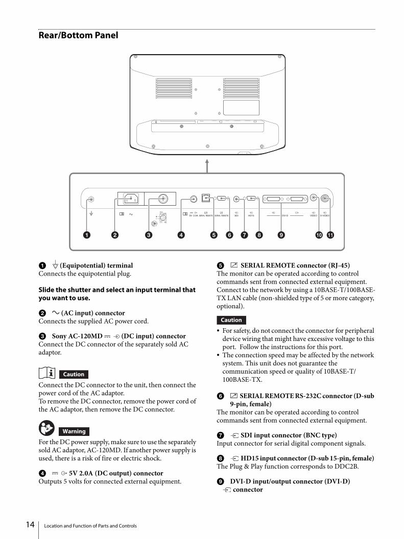
Rear/Bottom Panel
(Equipotential) terminalConnects the equipotential plug.
Slide the shutter and select an input terminal that you want to use.
(AC input) connectorConnects the supplied AC power cord.
Sony AC-120MD (DC input) connectorConnect the DC connector of the separately sold AC adaptor.
Connect the DC connector to the unit, then connect the power cord of the AC adaptor.To remove the DC connector, remove the power cord of the AC adaptor, then remove the DC connector.
For the DC power supply, make sure to use the separately sold AC adaptor, AC-120MD. If another power supply is used, there is a risk of fire or electric shock.
5V 2.0A (DC output) connectorOutputs 5 volts for connected external equipment.
SERIAL REMOTE connector (RJ-45)The monitor can be operated according to control commands sent from connected external equipment.Connect to the network by using a 10BASE-T/100BASE-TX LAN cable (non-shielded type of 5 or more category, optional).
For safety, do not connect the connector for peripheral device wiring that might have excessive voltage to this port. Follow the instructions for this port.
The connection speed may be affected by the network system. This unit does not guarantee the communication speed or quality of 10BASE-T/100BASE-TX.
SERIAL REMOTE RS-232C connector (D-sub 9-pin, female)
The monitor can be operated according to control commands sent from connected external equipment.
SDI input connector (BNC type)Input connector for serial digital component signals.
HD15 input connector (D-sub 15-pin, female) The Plug & Play function corresponds to DDC2B.
DVI-D input/output connector (DVI-D)connector
Location and Function of Parts and Controls

Input DVI Rev.1.0 applicable digital signal.connector
Active through output connector of the DVI digital signal.Outputs the signal which inputs to the connector.The signal protected by HDCP 1) is not output.
1) HDCP (High-bandwidth Digital Content Protection) is a copyright protection technology using encryption technology of digital video signals.
Note
A signal is output from the connector only when the monitor is turned on. When the monitor is turned off, the signal is not output from the connector.
VIDEO input connector (BNC type)The input connector for composite signals.
S-VIDEO input connector (4-pin mini-DIN)The input connector for Y/C signals.
Do not come into contact with the terminals of the rear panel connectors and patients at the same time.Doing so may result in a generation of voltage that can be harmful to patients if the unit is malfunctioning.Always disconnect the power cord before connecting and disconnecting connectors.
Using this unit for medical purposesThis equipment’s connectors are not isolated.Do not connect any device other than one which conforms to IEC 60601-1.When an information technology device or AV device that uses an alternating current is connected, current leakage may result in an electric shock to the patient or operator.If use of such a device is unavoidable, isolate its power supply by connecting an isolation transformer, or by connecting an isolator between the connecting cables.After implementing these measures, confirm that the reduced risk now conforms to IEC 60601-1.
Connecting the Power Cord
To connect the power cord
1 Press the side of the switch and switch the unit to the standby state.
2 Slide the shutter of the AC connector of the unit to the right, then insert the AC power cord into the AC input connector as illustrated.
To use the AC adaptor (sold separately)Switch the unit to the standby state by pressing the side of the switch, slide the shutter of the power connector on the unit to the left, then insert the DC connector into the DC input connector until it locks. Next, insert the AC power cord into the separately sold AC adaptor.
AC input connector
Shutter
AC power cord
AC plug holder
ShutterDC input connector
DC connector
Connecting the Power Cord 15

16
To remove the power cordSwitch the unit to the standby state by pressing the side of the switch, then remove the AC power cord. When using the separately sold AC adaptor, switch the unit to the standby state, remove the AC power cord from the AC adaptor, then remove the DC connector from the unit.
Initial Setting
When you turn on the unit for the first time after purchasing it, select the area and language where you intend to use this unit from among the options.
To set the using area
1 Turn on the unit.
The Area Setting screen appears.
2 Press the CONTROL button.
Color Temperature NTSC Setup
North America D65 7.5%Latin America - Argentina D65 0%Latin America - Paraguay D65 0%Latin America - Uruguay D65 0%Latin America - Other D65 7.5%Africa, AustralasiaEurope, Middle-East
D65 0%
Asia Except Japan - NTSC D65 7.5%Asia Except Japan - PAL D65 0%Japan D93 0%
Initial Setting

3 Press the or button to select the area where you intend to use the unit and press the button.
When the confirmation screen is displayed, press the or button to select Yes and press the CONTROL button.
If you select Asia Except JapanCustomers who will use this unit in the shaded areas shown in the map below except for Japan should select Asia Except Japan - NTSC.Other customers should select Asia Except Japan - PAL.
4 The Area Setting screen disappears and the menu item settings suitable for the selected area are applied.
Note
When you have selected the wrong area, set the following items using the menu. Color Temperature (on page 20) NTSC Setup (on page 21)See “To set the using area” (page 16) on the setting value.
To set the using languageYou can select one of eight languages (English, Chinese, Japanese, Italian, Spanish, German, French, and Russian) for display on the menu and other on-screen displays. The default menu language is set to “English.”
1 Turn on the unit.
Select the area where you intend to use this unit on the Area Setting screen. (See page 16.)
2 The Language Setting screen is displayed.
3 Press the or button to select the language and press the button.
When the confirmation screen is displayed, press or button to select Yes and press the CONTROL button.
To change the menu languageSelect the area and language which you use. See this section when you change the using language.
1 Press the MENU button.
The menu-selecting screen appears.The menu presently selected is shown in blue.
2 Press the / button to select “System Configuration.”
The “System Configuration” menu appears.The selected tab is displayed in blue.
3 Press the / button to select the “OSD Setting” tab.
The “OSD Setting” menu appears.
Initial Setting 17

18
4 Press the / button to select “Language.”
The selected item is displayed in blue.
5 Press the / button to select a language.
The menu changes to the selected language.
To clear the menuPress the MENU button.The menu disappears automatically if a button is not pressed for one minute.
Using the Menu
The unit is equipped with an on-screen menu for making various adjustments and settings such as picture control, input setting, setting change, etc.To change the menu language, refer to “To change the menu language” on page 17.
1 Press the CONTROL button.
The operation buttons are displayed.
2 Press the MENU button.
The menu-selecting screen appears.The menu presently selected is shown in blue.
3 Press the / button to select a menu.
When you press the or CONTROL button, the selected menu appears and setting items of the selected tab are displayed.
4 Press the / button to select the tab.
Using the Menu

The selected tab is shown in blue, and setting items of the selected tab appear.
5 Select an item.
Press the / button to select the item.The item to be changed is displayed in blue.
6 Make the setting or adjustment on an item.
When changing the adjustment level:To increase the number, press the button.To decrease the number, press the button.When selecting the setting:Press the / button to select the setting.
If the Control Lock is set to “On,” the setting cannot be changed.For details about Control Lock, see page 23.
About the memory of the settingsThe settings are automatically stored in the monitor memory.
About the control navigationDepending on the state, the operating buttons of the unit light as shown below:White light: Operable state.Green light: Operating state.Off: Unable to operate.
Adjustment Using the Menus
Items
The screen menu of this monitor consists of the following items.
Color Tone AdjustmentGammaPhaseChromaBrightnessContrastColor TemperatureGain R OffsetGain G OffsetGain B OffsetBias R OffsetBias G OffsetBias B OffsetMonoSharpness HSharpness VRGB RangeRGB/YPbPrSync DetectACCCTINTSC Setup
Screen ControlHD Scan SizeSD Scan SizeFlip PatternSD AspectAPAShift HShift VDot PhaseDot Pitch
PIP / POPClipping SizeSub Screen PositionPattern Skip
Input ConfigurationPort A Input SelectPort B Input Select
Adjustment Using the Menus 19

20
Input NamePower SupplyHDCP SettingAuto Input Select
System ConfigurationControl LockOSD SettingPower On SettingPower SaveSerial RemoteEthernet SettingCustom ButtonPanel DisplayMonitor Information
Initial SetupLanguagePort A Input SelectPort B Input SelectPattern SkipPIP / POPCustom ButtonAuto Input Select
PresetLoad User SettingSave User SettingUser NameLoad Default
Adjusting and changing the settings
Color Tone Adjustment menuThe Color Tone Adjustment menu is used to adjust picture quality for each input. You need to use the measurement instrument to adjust the color temperature.Recommended: Konica Minolta color analyzer CA-310
Submenu Setting
Gamma Select the appropriate gamma mode from among “1.8,” “2.0,” “2.2,” “2.4,” “2.6,” “DICOM.”“DICOM” is for reference, not diagnostic, purposes only.
Phase Adjusts color tones. The higher the setting, the more greenish the picture. The lower the setting, the more purplish the picture.
Chroma Adjusts color intensity. The higher the setting, the greater the intensity. The lower the setting, the lower the intensity.
Brightness Adjusts brightness.Contrast Adjusts contrast.Color Temperature Select the color temperature from
among “D56,” “D65,” “D93.”
Note
If the setting is changed, Gain R/G/B Offset and Bias R/G/B Offset are restored to 0 respectively.
Gain R OffsetGain G OffsetGain B Offset
Adjust color temperature in detail, and color balance (Gain).
Bias R OffsetBias G OffsetBias B Offset
Adjust color temperature in detail, and color balance (Bias).
Mono Sets the display to a monochrome picture. Set to “On” for a monochrome picture, set to “Off” for a normal (chromatic) picture.
Sharpness H Adjusts the horizontal sharpness. The higher the setting, the sharper the picture. The lower the setting, the softer the picture.
Sharpness V Adjusts the vertical sharpness. The higher the setting, the sharper the picture. The lower the setting, the softer the picture.
RGB Range Sets the RGB signal range. Select from among “Auto,” “Limited,” “Full.” If you set to “Auto,” this item is set to “Limited” when inputting video signal, and “Full” when inputting PC signals.
RGB/YPbPr Sets the input signal of the HD15 connector. Select from among “RGB,” “YPbPr.”
Note
Select “RGB” to display PC signals.Sync Detect Sets detection of the sync signal of the
input signal. Select from among “Auto,” “Internal,” “External.” If you set to “Auto,” external synchronization is prioritized. If there is no external synchronization, internal synchronization is set.
Adjustment Using the Menus
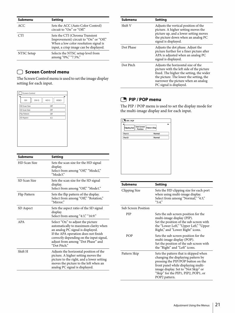
Screen Control menuThe Screen Control menu is used to set the image display setting for each input.
PIP / POP menuThe PIP / POP menu is used to set the display mode for the multi-image display and for each input.
ACC Sets the ACC (Auto Color Control) circuit to “On” or “Off.”
CTI Sets the CTI (Chroma Transient Improvement) circuit to “On” or “Off.” When a low color resolution signal is input, a crisp image can be displayed.
NTSC Setup Selects the NTSC setup level from among “0%,” “7.5%.”
Submenu Setting
HD Scan Size Sets the scan size for the HD signal display.Select from among “Off,” “Mode2,” “Mode3.”
SD Scan Size Sets the scan size for the SD signal display.Select from among “Off,” “Mode1.”
Flip Pattern Sets the flip pattern of the display.Select from among “Off,” “Rotation,” “Mirror.”
SD Aspect Sets the aspect ratio of the SD signal display.Select from among “4:3,” “16:9.”
APA Select “On” to adjust the picture automatically to maximum clarity when an analog PC signal is displayed.If the APA operation does not finish correctly depending on the input signal, adjust from among “Dot Phase” and “Dot Pitch.”
Shift H Adjusts the horizontal position of the picture. A higher setting moves the picture to the right, and a lower setting moves the picture to the left when an analog PC signal is displayed.
Submenu Setting
Shift V Adjusts the vertical position of the picture. A higher setting moves the picture up, and a lower setting moves the picture down when an analog PC signal is displayed.
Dot Phase Adjusts the dot phase. Adjust the picture further for a finer picture after APA is adjusted when an analog PC signal is displayed.
Dot Pitch Adjusts the horizontal size of the picture with the left side of the picture fixed. The higher the setting, the wider the picture. The lower the setting, the narrower the picture when an analog PC signal is displayed.
Submenu Setting
Clipping Size Sets the HD clipping size for each port when using multi-image display.Select from among “Normal,” “4:3,” “5:4.”
Sub Screen PositionPIP Sets the sub screen position for the
multi-image display (PIP).Set the position of the sub screen with the “Lower Left,” “Upper Left,” “Upper Right,” and “Lower Right” icons.
POP Sets the sub screen position for the multi-image display (POP).Set the position of the sub screen with the “Right” and “Left” icons.
Pattern Skip Sets the pattern that is skipped when changing the displaying pattern by pressing the PIP/POP button on the front panel while displaying multi-image display. Set to “Not Skip” or “Skip” for the PIP1, PIP2, POP1, or POP2 pattern.
Submenu Setting
Adjustment Using the Menus 21

22
Input Configuration menu
Submenu Setting
Port A Input Select Sets the input connector that is skipped when changing the input signal by pressing the PORT A button. Set to “Not Skip” or “Skip” for the SDI, DVI-D, HD15, VIDEO, S-VIDEO input connector.
Port B Input Select Sets the input connector that is skipped when changing the input signal by pressing the PORT B button. Set to “Not Skip” or “Skip” for the SDI, DVI-D, HD15, VIDEO, S-VIDEO input connector.
Input Name Sets the name for each input connector. Set the name of the SDI, DVI-D, HD15, VIDEO, S-VIDEO input connector. Endoscope Laparoscope Ultrasound Recorder Printer PACS C-arm Room Camera Surgical Camera Microscope Vital Device
Power Supply When the 5 V output power of the DVI input connector is output, “On” is set. When the power is not output, “Off” is set.
HDCP Setting Sets the HDCP setting for signals input in the DVI-D connector. Enable: Sets to use the signals
protected with HDCP. Disable: Sets to use the signals not
protected with HDCP. When “Disable” is set for the signals not protected with HDCP, signals are output from the DVI-D connector.
Note
When “Disable” is set for the signals protected with HDCP 1), images are not displayed.1) HDCP (High-bandwidth Digital
Content Protection) is a copyright protection technology using encryption technology of digital video signals.
Auto Input Select Sets the auto detection of the input signal.Select from among “Off,” “On.” On: Inputting signals to the input
connector automatically changes connectors.
Off: The Auto Input Select function does not operate.
Note
About Auto Input Select When “Auto Input Select” is set to
“On” and there is no input signal to any connector, inputting a signal to one of the connectors detects the signal and displays it on the screen.
When a signal is input to one of the connectors, the “Auto Input Select” function does not operate even if a signal is input to another connector.
When “Skip” is set for the signal input connector, the signal is displayed on the screen.
When using a multi-image display, the detected signal is displayed on the main display.
If a signal is detected while displaying the menu, the menu will be hidden.
Submenu Setting
Adjustment Using the Menus

System Configuration menu
Submenu Setting
Control LockControl Lock Set when you want to limit the
operation of the control panel. Set to “Off” for no limit, “On” to limit.
Lock Mode Sets the range to limit the operation of the control panel. This setting is available when “Control Lock” is set to “On.” Menu: Limits the menu operations
other than the control lock setting. Menu&Button: Limits all operations
other than the control lock setting.OSD Setting
Menu Position Sets the screen position for the OSD menu.Set the position of the OSD menu with the “Upper Left,” “Upper Right,” “Lower Right,” “Lower Left,” and “Center” icons.
Status Display Port, Flip Pattern, input connector name, signal format, PIP/POP mode, and control lock are displayed.
Select Port Input Terminal Operation lock display
Signal Format display
Flip Pattern PIP/POP mode display
Auto: The format and scan mode are displayed for about 3 seconds when the content of Status Display is changed.
On: The format and scan mode are always displayed.
Off: The format and scan mode are not displayed.
Notes
Even if the setting is set to “Auto” or “Off,” the flip pattern is available.
For details about the signal format, refer to no signal and incompatible signal displays.
Language You can select the menu or message language from the following languages. English: English : Chinese : Japanese Italiano: Italian Español: Spanish Deutsch: German Français: French Русский: Russian
Power On SettingPower On Mode Selects the setting when the monitor is
turned on from the following settings. Last: The setting when the monitor
was last turned off. Default Setting: The setting that is
set in the default setting. User1 to 20: The selected user
setting.Logo Select the logo when the power turns on
from among “On - 5sec,” “On - 10sec,” “On - 30sec,” “On - 60sec,” “On - 120sec,” “Off.”
Power SaveEnergy Saving Mode
Selects the energy saving mode. Off: Turns the energy saving mode
off. On: Dims the backlight.
Submenu Setting
Input Signal format display
No signal No SyncNon compatible signal (except for DVI-D)
Unknown
Non compatible signal (DVI-D)
Out Of Range
Adjustment Using the Menus 23

24
Initial Setup menuThe Initial Setup menu is used to set the default preset value.
Sleep Mode Sets the sleep mode to on or off. When you set to “On,” the monitor enters into power saving mode by turning off the backlight if there is no input signal from the selected connector for more than 1 minute.
Serial RemoteSerial Remote Selects the using mode.
Off: Disables the serial remote function.
RS-232C: Controls this unit via RS-232C command.
Ethernet: Controls this unit via Ethernet command.
Ethernet Setting Sets the Ethernet. IP Address: Sets the IP Address. Subnet Mask: Sets the Subnet Mask. Default Gateway: Sets “On” or “Off”
of the Default Gateway. Address: Sets the Default Gateway. Save: Saves the confirmed setting. Cancel: Returns to the previous
setting from the confirmed setting.Custom Button Assigns the function to the CUSTOM 1,
CUSTOM 2 or CUSTOM 3 button on the front panel, and can set the following functions to on or off. No Setting Scan Size Flip POP Sub Screen Position APA Gamma Mono Phase Chroma Brightness Contrast
Panel DisplayBacklight Adjusts the brightness of the display. A
higher setting increases the brightness of the display, and a lower setting darkens the display.
Monitor InformationSoftware Version Displays the software version.
Submenu Setting
Submenu Setting
Language You can select the menu or message language from the following languages. English: English : Chinese : Japanese Italiano: Italian Español: Spanish Deutsch: German Français: French Русский: Russian
Port A Input Select Sets the input connector that is skipped when changing the input signal by pressing the PORT A button. Set to “Not Skip” or “Skip” for the SDI, DVI-D, HD15, VIDEO, S-VIDEO connector.
Port B Input Select Sets the input connector that is skipped when changing the input signal by pressing the PORT B button. Set to “Not Skip” or “Skip” for the SDI, DVI-D, HD15, VIDEO, S-VIDEO connector.
Pattern Skip Sets the pattern that is skipped when changing the displaying pattern by pressing the PIP/POP button on the front panel while using multi-image display. Set to “Not Skip” or “Skip” for the PIP1, PIP2, POP1, or POP2 pattern.
PIP / POPPIP Sub Screen Position
Sets the sub screen position for the multi-image display (PIP).Set the position of the sub screen with the “Lower Left,” “Upper Left,” “Upper Right,” and “Lower Right” icons.
POP Sub Screen Position
Sets the sub screen position for the multi-image display (POP).Set the position of the sub screen with the “Right” and “Left” icons.
PORT A HD Clipping Size/PORT B HD Clipping Size
Sets the HD clipping size for each port when displaying multi-image display.Select from among “Normal,” “4:3,” “5:4.”
Adjustment Using the Menus
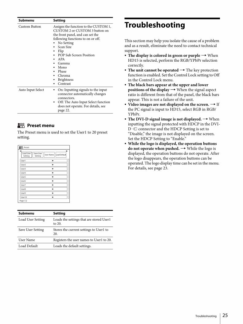
Preset menuThe Preset menu is used to set the User1 to 20 preset setting.
Troubleshooting
This section may help you isolate the cause of a problem and as a result, eliminate the need to contact technical support. The display is colored in green or purple When
HD15 is selected, perform the RGB/YPbPr selection correctly.
The unit cannot be operated The key protection function is enabled. Set the Control Lock setting to Off in the Control Lock menu.
The black bars appear at the upper and lower positions of the display When the signal aspect ratio is different from that of the panel, the black bars appear. This is not a failure of the unit.
Video images are not displayed on the screen. If the PC signal is input to HD15, select RGB in RGB/YPbPr.
The DVI-D signal image is not displayed. When inputting the signal protected with HDCP in the DVI-D connector and the HDCP Setting is set to “Disable,” the image is not displayed on the screen.Set the HDCP Setting to “Enable.”
While the logo is displayed, the operation buttons do not operate when pushed. While the logo is displayed, the operation buttons do not operate. After the logo disappears, the operation buttons can be operated. The logo display time can be set in the menu. For details, see page 23.
Custom Button Assigns the function to the CUSTOM 1, CUSTOM 2 or CUSTOM 3 button on the front panel, and can set the following functions to on or off. No Setting Scan Size Flip POP Sub Screen Position APA Gamma Mono Phase Chroma Brightness Contrast
Auto Input Select On: Inputting signals to the input connector automatically changes connectors.
Off: The Auto Input Select function does not operate. For details, see page 22.
Submenu Setting
Load User Setting Loads the settings that are stored User1 to 20.
Save User Setting Stores the current settings to User1 to 20.
User Name Registers the user names to User1 to 20.Load Default Loads the default settings.
Submenu Setting
Troubleshooting 25

26
Error Messages
When the following messages appear on the screen, turn off the power and contact an authorized Sony dealer.
Specifications
Picture performanceLCD panel a-Si TFT Active MatrixPixel efficiency 99.99%Viewing angle (panel specification)
89°/89°/89°/89° (typical) (up/down/left/right, contrast > 10:1)
Efficient picture sizeLMD-2735MD:
597.9 × 336.3, 686.0 mm (w/h, dia) (23 5/8 × 13 1/4, 27 1/8 inches)
LMD-2435MD:527.0 × 296.5, 604.7 mm (w/h, dia) (20 3/4 × 11 3/4, 23 7/8 inches)
Resolution H 1,920 dots, V 1,080 linesAspect ratio 16:9
InputVIDEO input (NTSC/PAL) connector
BNC type (1)1 Vp-p ± 3 dB sync negative
S-VIDEO input connector4-pin mini-DIN (1)Y: 1 Vp-p ± 3 dB sync negativeC: 0.286 Vp-p ± 3 dB (NTSC burst
signal level)0.3 Vp-p ± 3 dB (PAL burst signal level)
HD15 input connectorD-sub 15-pin (1)R/G/B: 0.7 Vp-p, sync positive
(Sync On Green, 0.3 Vp-p sync negative)
Sync: 0.3 Vp-p - 4.0 Vp-p(polarity free, H/V separate sync)
Plug & Play function: corresponds to DDC2B
DVI-D input connectorDVI-D connector (1)TMDS single link
SDI input connectorBNC type (1)
Remote input connectorSerial remote
D-sub 9-pin (RS-232C) (1)RJ-45 modular connector
(ETHERNET) (1)AC input connector
100 V to 240 V, 50/60 HzDC input connector
DC 24 V
Messages Description
Temperature Error The temperature of this unit has increased.
Error Messages / Specifications

OutputDVI-D output connector
DVI-D connector (1)Active through
DC 5V output connectorRound type pin (female) (1)
GeneralPower AC IN: 100 V - 240 V, 50/60 Hz, 0.6 A -
0.3 ADC IN: 24 V, 2.2 A (Supplied from AC
adaptor)Power consumption
Maximum: approx. 57 WOperating conditions
Temperature0 °C to 35 °C (32 °F to 95 °F)
Recommended temperature20 °C to 30 °C (68 °F to 86 °F)
Humidity 30% to 85% (no condensation)Pressure 700 hPa to 1060 hPa
Storage and transport conditionsTemperature
–20 °C to +60 °C (–4 °F to +140 °F)Humidity 20% to 90%Pressure 700 hPa to 1060 hPa
Accessories suppliedAC plug holder (2)Before Using This Unit (1)CD-ROM (including the Instructions
for Use) (1)Service Contact List (1)European Representative (1)
Optional accessoriesMonitor stand
SU-600MDSignal cable
SMF-405AC adaptor
AC-120MD
Medical SpecificationsProtection against electric shock: Class IProtection against harmful ingress of water: IPX1 (only when used vertically)Degree of safety in the presence of a flammable anesthetic mixture with air or with oxygen or nitrous oxide: Not suitable for use in the presence of a flammable anesthetic mixture with air or with oxygen or nitrous oxideMode of operation: Continuous
Design and specifications are subject to change without notice.
Pin assignment
SERIAL REMOTE (RS-232C) connectorD-sub 9-pin, female
5V 2.0A (DC output) connector
Notes Always verify that the unit is operating properly
before use. SONY WILL NOT BE LIABLE FOR DAMAGES OF ANY KIND INCLUDING, BUT NOT LIMITED TO, COMPENSATION OR REIMBURSEMENT ON ACCOUNT OF THE LOSS OF PRESENT OR PROSPECTIVE PROFITS DUE TO FAILURE OF THIS UNIT, EITHER DURING THE WARRANTY PERIOD OR AFTER EXPIRATION OF THE WARRANTY, OR FOR ANY OTHER REASON WHATSOEVER.
SONY WILL NOT BE LIABLE FOR CLAIMS OF ANY KIND MADE BY USERS OF THIS UNIT OR MADE BY THIRD PARTIES.
SONY WILL NOT BE LIABLE FOR THE TERMINATION OR DISCONTINUATION OF ANY SERVICES RELATED TO THIS UNIT THAT MAY RESULT DUE TO CIRCUMSTANCES OF ANY KIND.
Pin number Signal
1 NC2 RX3 TX4 NC5 GND6 NC7 NC8 NC9 NC
Pin number Signal
1 5 V2 NC3 GND
Specifications 27

28
Available signal formats
Analog signal
Digital signal
Signal format
Input connector
VIDEO S-VIDEO HD15
COMPONENT RGB
NTSC – –
PAL – –
480/59.94i – –
480/60i – –
480/60p – –
576/50i – –
576/50p – –
720/59.94p – –
720/60p – –
720/50p – –
1080/59.94i – –
1080/60i – –
1080/50i – –
Signal format
Input connector
SDI DVI-D
480/59.94i –
480/60p –
575/50i –
576/50p –
720/59.94p
720/60p
720/50p
1080/59.94i
1080/60i
1080/50i
1080/59.94p –
1080/60p –
1080/50p –
Specifications

Analog PC signal
VESA DMT
VESA CVT
Resolution Dot clock[MHz]
fH[kHz]
fV[Hz]
Sync. polarity
Horizontal Vertical
640 × 480 60 Hz 25.175 31.469 59.940 Negative Negative
800 × 600 56 Hz 36.000 35.156 56.250 Positive Positive
800 × 600 60 Hz 40.000 37.879 60.317 Positive Positive
800 × 600 72 Hz 50.000 48.077 72.188 Positive Positive
800 × 600 75 Hz 49.500 46.875 75.000 Positive Positive
800 × 600 85 Hz 56.250 53.674 85.061 Positive Positive
1024 × 768 60 Hz 65.000 48.363 60.004 Negative Negative
1024 × 768 70 Hz 75.000 56.476 70.069 Negative Negative
1024 × 768 75 Hz 78.750 60.023 75.029 Positive Positive
1024 × 768 85 Hz 94.500 68.677 84.997 Positive Positive
1152 × 864 75 Hz 108.000 67.500 75.000 Positive Positive
1280 × 960 60 Hz 108.000 60.000 60.000 Positive Positive
1280 × 1024 60 Hz 108.000 63.981 60.020 Positive Positive
1600 × 1200 60 Hz 162.000 75.000 60.000 Positive Positive
Resolution Dot clock[MHz]
fH[kHz]
fV[Hz]
Sync. polarity
Horizontal Vertical
640 × 480 60 Hz 23.625 29.531 59.780 Positive Negative
800 × 600 60 Hz 35.500 36.979 59.837 Positive Negative
1024 × 768 60 Hz 56.000 47.297 59.870 Positive Negative
1280 × 960 60 Hz 85.250 59.201 59.920 Positive Negative
1600 × 1200 50 Hz 132.375 61.742 49.994 Negative Positive
1600 × 1200 60 Hz 130.375 74.077 59.981 Positive Negative
1360 × 768 50 Hz 69.500 39.489 49.922 Negative Positive
1360 × 768 60 Hz 84.625 47.649 59.936 Negative Positive
1360 × 768 60 Hz 72.000 47.368 59.960 Positive Negative
1920 × 1080 50 Hz 141.375 55.572 49.975 Negative Positive
1920 × 1080 60 Hz 138.625 66.647 59.988 Positive Negative
1920 × 1200 50 Hz 158.000 61.719 49.975 Negative Positive
1920 × 1200 60 Hz 154.125 74.099 59.999 Positive Negative
1280 × 1024 60 Hz 91.000 63.194 59.957 Positive Negative
1280 × 768 50 Hz 65.125 39.518 49.959 Negative Positive
1280 × 768 60 Hz 80.125 47.693 59.992 Negative Positive
Specifications 29
30
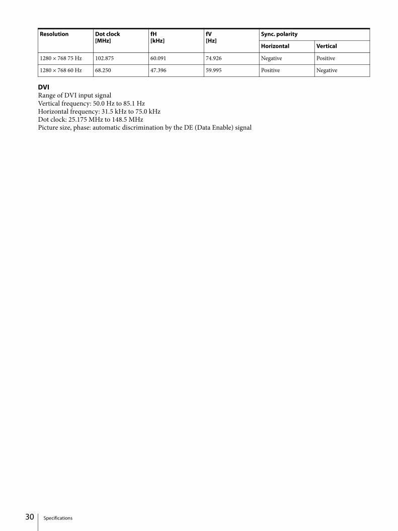
DVIRange of DVI input signalVertical frequency: 50.0 Hz to 85.1 HzHorizontal frequency: 31.5 kHz to 75.0 kHzDot clock: 25.175 MHz to 148.5 MHzPicture size, phase: automatic discrimination by the DE (Data Enable) signal
1280 × 768 75 Hz 102.875 60.091 74.926 Negative Positive
1280 × 768 60 Hz 68.250 47.396 59.995 Positive Negative
Resolution Dot clock[MHz]
fH[kHz]
fV[Hz]
Sync. polarity
Horizontal Vertical
Specifications

Dimensions
LMD-2735MD
Front
When an optional stand SU-600MD is attached
Rear (VESA Mount Instruction)
Side
When an optional stand SU-600MD is attached
Unit: mm (inches)Mass:
Approx. 8.7 kg (19 lb 2.9 oz) (when the optional stand is not installed)
LMD-2435MD
Front
When an optional stand SU-600MD is attached
* Length of M4 screws (4)
Monitor cabinet Attached object
6 (1/4) to 9 (3/8)M4 screw
Dimensions 31

32
Rear (VESA Mount Instruction)
Side
When an optional stand SU-600MD is attached
Unit: mm (inches)Mass:
Approx. 6.7 kg (14 lb 12 oz) (when the optional stand is not installed)
* Length of M4 screws (4)
Monitor cabinet Attached object
6 (1/4) to 9 (3/8)M4 screw
Dimensions