LCD Digital Storage Oscilloscope Operating … Digital Storage Oscilloscope Operating Instructions...
4
DN062-06v05 JYE Tech - 1 - www.jyetech.com LCD Digital Storage Oscilloscope Operating Instructions Model: 06201 1. Accessories 1) Simple probe 2) AC/DC Power adapter (universal input voltage range) 2. Precautions 1) Do not apply voltage higher than the specified maximum input voltage to the instrument. 2) Do not attempt to directly measure wall power supply without a transformer. 3) Do not use power supply with voltage higher than 12V (DC or rms) 3. Panel Descriptions Fig 1 shows the screen and various controls at the front panel. They are explained below. Screen 1) Y position indicator –the left small triangle –shows 0V position 2) Trig level indicator –the small right triangle –shows trigger threshold voltage level 3) Window position indicator –reflects the displayed portion of sample memory. Fig. 1
-
Upload
nguyenmien -
Category
Documents
-
view
229 -
download
5
Transcript of LCD Digital Storage Oscilloscope Operating … Digital Storage Oscilloscope Operating Instructions...

DN062-06v05
JYE Tech - 1 - www.jyetech.com
LCD Digital Storage Oscilloscope
Operating Instructions Model: 06201
1. Accessories 1) Simple probe 2) AC/DC Power adapter (universal input voltage range)
2. Precautions 1) Do not apply voltage higher than the specified maximum input voltage to the
instrument. 2) Do not attempt to directly measure wall power supply without a transformer. 3) Do not use power supply with voltage higher than 12V (DC or rms)
3. Panel Descriptions Fig 1 shows the screen and various controls at the front panel. They are explained below.
Screen 1) Y position indicator – the left small triangle – shows 0V position 2) Trig level indicator – the small right triangle – shows trigger threshold voltage level 3) Window position indicator – reflects the displayed portion of sample memory.
Fig. 1

DN062-06v05
JYE Tech - 2 - www.jyetech.com
Fig. 3
4) “HOLD” is displayed when the oscilloscope is in HOLD state, which means capturing is halted until HOLD state is released.
5) Scope setting indicators – their meanings are shown in Fig. 2.
Power Supply Connector Located at bottom right of the
panel. 9 – 12V DC power supply (minimum 300mA capacity) can be connected to this connector.
Signal Input Connector Located at bottom left of the
panel.
Coupling Select Switch This switch selects the coupling method to be used, i.e. AC coupling or DC coupling. When it is placed at
“Freq. M.” position input is connected to frequency measurement circuit. The input to scope is disconnected.
Y Sensitivity Select Switches There are two switches for Y sensitivity selection. The first one selects base value. The second selects rate.
The two settings are combined to determine actual Y sensitivity. For example, when switch Y SEN. 1 is put at “0.1V” position and switch Y SEN 2 is placed at “X2” position, this means actual Y sensitivity is 0.2V per division.
SEC/DIV Selects horizontal timebase. When this button is pressed timebase display will be highlighted and timebase
setting can be adjusted by pressing [ + ] and [ - ] buttons.
V.POS Selects vertical position. When this button is pressed vertical position adjustment indicator will be highlighted
and vertical position can be adjusted with [ + ] and [ - ] buttons.
H.POS Selects horizontal position. When this button is pressed horizontal position adjustment indicator will be
highlighted and the displayed portion of capture buffer can be adjusted horizontally with [ + ] and [ - ] buttons.
MODE Selects trig modes. When this button is pressed trig mode adjustment indicator will be highlighted and trig
mode can be selected with [ + ] and [ - ] buttons.
SLOPE Selects trigger polarity. When this button is pressed slope select indicator will be highlighted. Trigger slope
will be toggled between rising and falling. Alternatively, trig slope can be changed with [ + ] and [ - ] buttons when the indicator is highlighted.
LEVEL Selects trigger level. When this button is pressed trig level
adjustment indicator will be highlighted and trig level can be adjusted with [ + ] and [ - ] buttons. Press this button again will toggle trig source between internal and external.
OK Switches oscilloscope between HOLD and RUN states. When
this button is held down for more than 3 seconds the instrument will switch between Oscilloscope Mode and Frequency Meter Mode.
4. General Measurement
Example 1 Observe the test signal (Practice for basic operations) 1) Connect power supply and probe. 2) Connect the red clamp to the test signal terminal locates at top-left corner of the panel, as shown in Fig.
3. 3) Set Y sensitivity switch 1 (the middle one) to 1V position.
Fig. 2
DN062-06v05
JYE Tech - 3 - www.jyetech.com
Fig. 4
Fig. 5
4) Set coupling switch to DC position. 5) Press [ V.POS ] button, adjust 0V indicator to the second last vertical scale as shown in Fig. 3. 6) Press [SEC/DIV] button, set timebase to 1ms. 7) Set Y sensitivity switch 2 (to top one) to X2 position. Waveform similar to that shown in Fig. 3 should
be seen. 8) Change positions of Y sensitivity switch 2 you should see waveform amplitude changes accordingly. 9) Change timebase setting to 0.5ms, for instance, you should be able to see the signal high/low level is
widened accordingly. Try other settings to explore.
10) Now put coupling switch to AC position you should see waveform is shifted down to a position where the Y Pos. indicator is at its middle point. This means what you see is a pure alternative signal.
Example 2 Observe saw signal (Learn how to use trigger modes ) Fig. 4 is a simple saw signal generator. We can use the scope to observe its output. Build the circuit according
to Fig. 4 and connect power and the scope. 1) Select DC coupling. Set Y sensitivity switch 1 to 1V
position and Y sensitivity switch 2 to X2 position. Adjust the 0V point to the second last vertical scale. Select 0.1ms timebase.
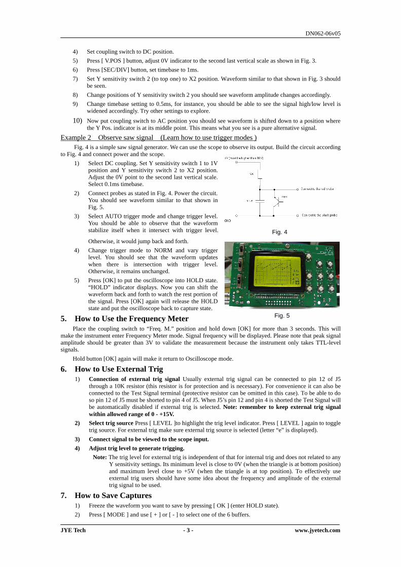
2) Connect probes as stated in Fig. 4. Power the circuit. You should see waveform similar to that shown in Fig. 5.
3) Select AUTO trigger mode and change trigger level. You should be able to observe that the waveform stabilize itself when it intersect with trigger level.
Otherwise, it would jump back and forth. 4) Change trigger mode to NORM and vary trigger
level. You should see that the waveform updates when there is intersection with trigger level. Otherwise, it remains unchanged.
5) Press [OK] to put the oscilloscope into HOLD state. “HOLD” indicator displays. Now you can shift the waveform back and forth to watch the rest portion of the signal. Press [OK] again will release the HOLD state and put the oscilloscope back to capture state.
5. How to Use the Frequency Meter Place the coupling switch to “Freq. M.” position and hold down [OK] for more than 3 seconds. This will
make the instrument enter Frequency Meter mode. Signal frequency will be displayed. Please note that peak signal amplitude should be greater than 3V to validate the measurement because the instrument only takes TTL-level signals.
Hold button [OK] again will make it return to Oscilloscope mode.
6. How to Use External Trig 1) Connection of external trig signal Usually external trig signal can be connected to pin 12 of J5
through a 10K resistor (this resistor is for protection and is necessary). For convenience it can also be connected to the Test Signal terminal (protective resistor can be omitted in this case). To be able to do so pin 12 of J5 must be shorted to pin 4 of J5. When J5’s pin 12 and pin 4 is shorted the Test Signal will be automatically disabled if external trig is selected. Note: remember to keep external trig signal within allowed range of 0 - +15V.
2) Select trig source Press [ LEVEL ]to highlight the trig level indicator. Press [ LEVEL ] again to toggle trig source. For external trig make sure external trig source is selected (letter “e” is displayed).
3) Connect signal to be viewed to the scope input. 4) Adjust trig level to generate trigging.
Note: The trig level for external trig is independent of that for internal trig and does not related to any Y sensitivity settings. Its minimum level is close to 0V (when the triangle is at bottom position) and maximum level close to +5V (when the triangle is at top position). To effectively use external trig users should have some idea about the frequency and amplitude of the external trig signal to be used.
7. How to Save Captures 1) Freeze the waveform you want to save by pressing [ OK ] (enter HOLD state). 2) Press [ MODE ] and use [ + ] or [ - ] to select one of the 6 buffers.

DN062-06v05
JYE Tech - 4 - www.jyetech.com
3) Press [ OK ] to save the frozen waveform to the buffer selected.
8. How to Display Saved Captures 1) Enter HOLD state by pressing [ OK ]. 2) Press [ SLOPE ] and use [ + ] or [ - ] to select the buffer to be displayed. 3) Press [ OK ] to display the waveform in the buffer selected.
9. How to Send Screen to PC as Bitmap File The oscilloscope screen can be transferred to PC as bitmap file through serial connection. The transfer
protocol is Xmodem. Communication format is 38400bps, 8 data bits, 1 stop bit, no polarity, no flow control. To do this follow the steps below:
1) Connect the scope to PC via a serial level converter. (For how to make serial connection and level converter please refer to related documents and products at www.jyetech.com website.)
2) Launch Windows HyperTerminal (or any other communication tool that can handle Xmodem protocol) and prepare it for file reception. Please make sure that the filename of received file has “.bmp” extension. (Suggestion: it is a good idea to put vertical scale info into filename for future reference.)
3) Put scope into HOLD state and display an interested portion of a capture on screen. 4) Press [ LEVEL ] then [ OK ]. Scope screen will be sent to PC as a bitmap file.
10. Features & Specifications Max Sample Rate 5M samples/second *
Resolution 8 bits
Sample Memory Depth 256 bytes
Analog Bandwidth 1MHz
Vertical Sensitivity 100mV/Div – 5V/Div
Input Impedance 1MO
Max Input Voltage 50Vpp
Coupling DC/AC
Trigger Modes Auto, Normal, and Single
Trigger Polarity Rising/Falling
Trig position 1/4 of sample buffer (fixed)
External Trig Input Range 0 – 15V
Save up to 6 captures to EEPROM
Display saved captures
Transfer screen as bitmap file to PC via serial port
Backlit LCD display
Power Supply Voltage 9 DC
Oscilloscope
Power Supply Current < 280mA
Frequency Range 5MHz Frequency Meter
Sensitivity 3Vpp
Dimension 110mm X 65mm X 25mm Overall
Weight 70 grams (board & probe)
* 5Msps only works in AUTO mode