LCD Digital Storage Oscilloscope Manual of Operation · LCD Digital Storage Oscilloscope Manual of...
8
DN082-02v02 JYE Tech - 1 - www.jyetech.com LCD Digital Storage Oscilloscope Manual of Operation Applicable Models: 08201/08201B, 08202/08202B 1. Packing List Items 08201/08201B 08202/08202B 082 Digital Storage Oscilloscope 1 1 AC/DC Power Adapter 1 1 BNC Probe 1 Operating Manual 1 1 2. Precautions 1) Do not use a supply voltage higher than the specified maximum input voltage of 9-12VDC to the instrument, as this may damage it and also invalidate your warranty. 2) Do not attempt to directly measure mains power supply without using a step down transformer. DO NOT EXCEED 50V MAX 3. Panel Description The photo above shows the screen and various front panel controls. They are explained respectively below. Screen 1) Vertical position indicator – the small triangle on the left border of the grid– indicates the 0 volt input level. Its position can be changed up or down, by pressing [VPOS] and turning the adjustment knob. 2) Trigger level indicator – the small triangle on the right border of the grid – shows the threshold voltage of trigger. It is triggered when the input signal level crosses the threshold voltage level; the trigger level is referenced to the input signal ground. 3) Window position indicator – indicates the displayed portion of sampled memory. The distance between the two short vertical bars at the bottom represents the whole length of sampled memory, which is usually much longer than the screen can display. So at any given moment the screen can only display a portion of the sampled data. The window position indicator shows which portion is being Fig 1
Transcript of LCD Digital Storage Oscilloscope Manual of Operation · LCD Digital Storage Oscilloscope Manual of...

DN082-02v02
JYE Tech - 1 - www.jyetech.com
LCD Digital Storage Oscilloscope
Manual of Operation Applicable Models: 08201/08201B, 08202/08202B
1. Packing List
Items 08201/08201B 08202/08202B 082 Digital Storage Oscilloscope 1 1
AC/DC Power Adapter 1 1
BNC Probe 1
Operating Manual 1 1
2. Precautions 1) Do not use a supply voltage higher than the specified maximum input voltage of
9-12VDC to the instrument, as this may damage it and also invalidate your warranty.
2) Do not attempt to directly measure mains power supply without using a step down transformer. DO NOT EXCEED 50V MAX
3. Panel Description
The photo above shows the screen and various front panel controls. They are explained respectively below.
Screen 1) Vertical position indicator – the small triangle on the left border of the grid– indicates the 0 volt input
level. Its position can be changed up or down, by pressing [VPOS] and turning the adjustment knob. 2) Trigger level indicator – the small triangle on the right border of the grid – shows the threshold
voltage of trigger. It is triggered when the input signal level crosses the threshold voltage level; the trigger level is referenced to the input signal ground.
3) Window position indicator – indicates the displayed portion of sampled memory. The distance between the two short vertical bars at the bottom represents the whole length of sampled memory, which is usually much longer than the screen can display. So at any given moment the screen can only display a portion of the sampled data. The window position indicator shows which portion is being
Fig 1

DN082-02v02
JYE Tech - 2 - www.jyetech.com
Fig 2
displayed. By pressing [HPOS] and then turning adjustment knob you can pan through the samples in memory.
4) Trigger point indicator – indicates the point where trigger occurs. Depending on the trigger position setting the trigger point can be set to 1/8, 1/4, 1/2, 3/4, or 7/8 of the sample memory. With the trigger point indicator users can visually identify the exact spot where trigger occurs. When the trigger point is outside of the display window, it will be indicated by a small triangle, pointing either left or right.
5) “HOLD” is displayed when the oscilloscope is in HOLD state, which means capture action is halted until HOLD state is released.
6) Parameter setting indicators – their functions are described below.
Adjustment Knob This is rotary pot for generic setting adjustments. Turning this knob will affect the selected (highlighted)
parameter. This knob also serves as power switch. When power supply is connected pressing this knob will turn the oscilloscope on. When the oscilloscope is on pressing and holding this knob for 2 – 3 seconds will turn the unit off.
Coupling Select Switch This switch selects which coupling method to be used. “DC” means input signal is directly applied to the
oscilloscope. “AC” means input signal is connected to the oscilloscope via a capacitor, which blocks the DC component of input signal. When this switch is set to “GND” the input signal is disconnected and oscilloscope input is connected to ground.
Vertical Sensitivity Select Switches There are two switches for vertical sensitivity selection: The first one selects base value. The second selects
multiplier. A combination of the two settings determines actual vertical sensitivity. For example, when switch V. SEN. 1 is in the “0.1V” position and switch V SEN 2 is in the “X2” position, the actual vertical sensitivity is (0.1 x 2 = 0.2) which means 0.2V per division.
SEC/DIV Select time-base. When this button is pressed the time-base display will be highlighted. Time-base settings
can be adjusted by turning the adjustment knob.
V.POS Select vertical position. When this button is pressed, the vertical position adjustment indicator will be
highlighted and vertical position can be adjusted by turning the adjustment knob.
H.POS Select horizontal position. When this button is pressed, the horizontal position adjustment indicator will be
highlighted and the displayed portion of captured signal sample in the buffer can be adjusted horizontally by turning the adjustment knob.
MODE Selects trigger modes. When this button is pressed, the trigger mode adjustment indicator will be highlighted
and the trigger mode can be selected by turning the adjustment knob.
SLOPE Selects trigger polarity. When this button is pressed, the slope select indicator will be highlighted. The
trigger slope will be toggled between rising and falling.

DN082-02v02
JYE Tech - 3 - www.jyetech.com
LEVEL Selects trigger level. When this button is pressed, the trigger level adjustment indicator will be highlighted
and the trigger level can be adjusted by turning the adjustment knob. Pressing this button again will toggle the trigger source between internal and external.
HOLD Toggle the oscilloscope between HOLD and RUN states.
4. Connectors and Terminals
Power Supply Connector This connector is located at bottom right of the panel. A 9 – 12V DC power supply with minimum 500mA
capacity should be used. Even though there is over-voltage protection, a power supply voltage higher than 13V should be avoided. The centre conductor of the connector is the positive pole of the power supply.
Signal Input Connector This connector locates at bottom left of the panel. This is a standard BNC connector for oscilloscope probe.
Please note that with a 1X probe the maximum peak-to-peak voltage applied to this input should not be greater than 50V. If measurement for larger voltage is needed appropriate divider (use 10X probe, for example) should be provided.
USB Connector This connector locates at the right side of oscilloscope. This is a 5-pin mini USB B type connector. It is for
firmware upgrading and data transferring to/from PC.
M.F.T. Connector The Multi-Function Terminal (M.F.T.) locates at the left side of oscilloscope. It serves two purposes: 1) Test Signal output 2) External Trigger input The function of M.F.T. is selected by [LEVEL] key and indicated by the small letter at the right of trigger
mode indicator. The table below summarizes the functions of M.F.T.
Indicator Trigger Source Test Signal Output
“ i “ Internal Enabled
“ e “ External Disabled
5. Basic Operations
Power Up Connect power adapter to the connector at bottom-right and push the [KNOB] button. The oscilloscope first
enters bootloader and stays for 1 – 2 seconds, and waits for firmware upgrade request. If no upgrade request is detected control is passed to main firmware. Logo and firmware version information will be briefly displayed and then oscilloscope enters normal working state.
Set Parameters The basic and most frequently used oscilloscope parameters are: 1) Vertical related – sensitivity, vertical position [VPOS], and AC/DC coupling. 2) Horizontal related – Time-base [SEC/DIV] and horizontal position [HPOS]. 3) Trigger – trigger modes [MODE], edges [SLOPE], source, and level [LEVEL].
Please refer to the descriptions in Section 4 for how to use these controls to change the parameters.
Example 1 Observe the test signal (Practice basic operations) 1) Place the tip of the probe on the centre conductor of the BNC
connecter marked M.F.T. This is the output of built-in 1KHz/5Vpp test signal. Remember to set the attenuation switch at probe handle to 1X position.
2) Press the [LEVEL] button to set the trigger source to internal (letter ‘i’ should be displayed. Otherwise you won’t get test signal output.)
Fig 3

DN082-02v02
JYE Tech - 4 - www.jyetech.com
(a) Under compensation (b) Right compensation (c) Over compensation
Fig 4
Fig 5
Fig 6
3) Set vertical sensitivity to 2V (V.Sen 1 switch in position “1V” And V. Sen 2 switch in position “X2”). 4) Set the coupling switch to the “DC” position. (See Fig 3) 5) Press the [ V.POS ] button, and adjust 0V indicator to the position shown in Fig. 3. 6) Press the [ SEC/DIV ] button, and set the Time-base to 0.5ms. Waveform shown in Fig. 3 should be
seen. (If you find the display is unstable, you can press [LEVEL] and turn the knob so that a stable display is obtained.)
7) Changing position of V. Sen 2 switch you should see that the waveform amplitude changes accordingly. You can compare the amplitude readings.
8) Changing the Time-base setting to 0.2ms, for instance, you should see the signal waveform widens accordingly. Compare readings and experiment with other settings.
9) Now, select “AC” with the coupling switch and you should see that the waveform is shifted down to a position where the VPos indicator is at its midway point.
Example 2 Observe saw signal (Learn how to use trigger modes)
The schematic on the right is a simple sawtooth signal generator. We are going to use the scope to observe its output. Build the circuit according to the schematic. Connect power and oscilloscope as indicated.
1) Select coupling switch to DC. Set V. Sen. 1 switch to the “1V” position and V. Sen. 2 switch to the “X2” position. (i.e. sensitivity is set to 2V/Div). Adjust the 0V to the second last point on the vertical scale. (See Fig 4)
2) Power the circuit. Select Time-base to 0.5ms (or other depending on type of transistor used). You should see a waveform similar to that shown in Fig 4.
3) Select AUTO trigger mode and change the trigger level. You should be able to observe that the waveform stabilizes itself when it intersects with trigger level (the internal trigger source should be selected here). Otherwise, the waveform will jump and you won’t be able to get a clear view of it.
4) Change the trigger mode to NORM, and vary the trigger level. Notice that the waveform only update when they intersect with the trigger level (internal trigger source should also be selected here). Otherwise, it will stall.
5) Press the [HOLD] button to put the oscilloscope into the HOLD state. “HOLD” is displayed. Now you can shift the waveform back and forth to view the un-displayed waveform. Pressing [HOLD] again will release the HOLD state and put oscilloscope back into captured signal sample state.
Use 10X Probe 10X probe offers the advantage of higher input voltage range, higher
impedance, and less interference to the circuits being measured. In order to effectively use 10X probe the compensation cap trimmer (see Fig 5) must be calibrated. This can be done using the built-in 1KHz/5V test signal.
Set the probe attenuation to 1/10 by setting the attenuation switch in the probe handle to the “10X” position. Insert the probe tip into the centre conductor of M.F.T. connector. Set oscilloscope Time-base to 0.2ms/Div and adjust trigger level so that a stable waveform display is obtained. Tune the cap trimmer carefully (see Fig 5) so that right compensation figure is reached (refer to Fig 6).
At using 10X probe remember to multiply vertical reading by 10 for true results. If, for example, the displayed signal amplitude is 2.5V the real signal amplitude is actually 25V.

DN082-02v02
JYE Tech - 5 - www.jyetech.com
Fig 7
Fig 8
Vertical Position Zeroing Sometimes you may find the vertical position indicator is not aligned to 0V level trace. This is caused by two
factors. 1) Component errors. 2) Interference from the ADC clock. In order to reduce the misalignment a “Vertical Position Zeroing” function was implemented as workaround on
the DSO082. What it actually does is to add correction values to samples so that misalignment does not appear to be that large. However, even with this correction some misalignment still exists (varies depending on Time-base settings between 1 – 3 pixels,). This misalignment causes some inconvenience but will not affect the measurement results. Users can use the VPos triangle as a rough indicator only. Use where the 0V level is as a reference point and start measurements from there.
To use the “Vertical Position Zeroing” function first set the coupling switch to the “GND” position. Then press [VPOS] button and hold it down for about 3 seconds. The VPos zeroing prompt screen will appear. Follow the instructions on the screen to continue.
Please note that vertical position zeroing is dependent upon the individual Time-base setting. This means that for each Time-base setting there is a specific correction value, which the zeroing process generates for that individual Time-base. But 1ms/Div Time-base is special. Zeroing carried under 1ms/Div will set all corrections to the same value. So for a new oscilloscope vertical position zeroing should be first done to 1ms/Div. Usually once zeroing under 1ms/Div is done VPos alignments for most of the rest Time-base settings are ok. If the misalignment is found too large for an individual Time-base, then you should carry out zeroing for that Time-base.
Rolling Display Mode When Time-base is set to 0.1s/Div or slower DSO 082 uses a display mode called “Rolling”. In this mode the
trace shifts from right to left, simulating time passing.
LCD Backlight ON/OFF Pressing [MODE] and [LEVEL] at the same time will toggle the LCD backlight ON/OFF. This is useful when
the oscilloscope is running on battery power.
Power Off To power off the oscilloscope push down the adjustment knob and hold it for about 3 seconds. The oscilloscope
will enter stand-by mode where most of circuits are powered off. Only keypad remains active.
6. Advanced Operations
Select Record Length In normal running mode pushing and holding down the [HPOS] button
will make the device enter the Record Length Selection screen (see Fig 7). Use the adjustment knob to select the record length you want and press [HOLD] to Exit and return to normal running mode.
For most applications record length of 2000 points is enough and is thus recommended. This will allow the oscilloscope response time to be faster. If a longer record length is selected the slower the response will be expected because the device needs more time load the buffer before starting a new captured signal sample. Particularly, when the Time-base is set to 20ms/Div or 50ms/Div and the record length of 10000 or larger is selected; you will see a significantly slower display update.
Change Trigger Position In normal running mode pushing and holding down the [LEVEL] button
will make the device enter the Trigger Position selection screen (see Fig 8). Use the adjustment knob to select the trigger position you want and pressing the [HOLD] button Exits and returns to normal running mode.
The Trigger position can be set to 1/8, 1/4, 1/2, 3/4, or 7/8 in the captured signal sample buffer (regardless of record length setting). If the trigger position is set to 1/8 this means the first 1/8 of the buffer keeps the sample taken before trigger point, and 7/8 of the buffer keeps a sample taken after the trigger point. If the trigger position is set to 1/2 this means buffer size used to keep samples before and after trigger point is half and half. Apparently, if you are more interested in waveforms after the trigger point you should set the trigger position to a smaller value. And if you are more interested in a signal before the trigger then a larger trigger position setting should be used.
USB Connection The USB connection used in 082 is a virtual Uart port based on the dedicated Uart-USB convert chip CP2102
from Silicon Lab. To use the connection, you need to install the PC drivers. Drivers for Windows and Linux can be downloaded from the Silicon Lab’s web site.

DN082-02v02
JYE Tech - 6 - www.jyetech.com
Fig 9
Fig 10
Fig 11
Download link: http://www.silabs.com/products/mcu/pages/usbtouartbridgevcpdrivers.aspx
Save captured signal samples
Captured waveforms can be stored in the on-chip EEPROM for later use. Do This by:
1) Freeze the waveform you intend to save by pressing [HOLD] key (enter HOLD state).
2) Press [SLOPE] and use [KNOB] to select one of the 4 buffers. 3) Press [VPOS] to enter save captured signal sample screen. 4) Press [HOLD] to save the frozen waveform to the buffer selected.
Recall captured signal samples To recall saved waveforms: 1) Enter HOLD state by pressing [HOLD]. 2) Press [SLOPE] and use [KNOB] to select the buffer to be recalled. 3) Press [HOLD] to display the waveform in the buffer selected.
Send Screen as Bitmap File The oscilloscope screen can be transferred to a PC as a bitmap file via the
USB. The transfer protocol used here is Xmodem. Communication format is 38400bps, 8 data bits, 1 stop bit, no parity, no flow control. To do this, please follow the steps below:
1) Install Virtual Com Port driver if you have not already done so. 2) Connect the scope to PC via a mini USB cable. 3) Launch Windows HyperTerminal (or any other communication tool
that can handle the Xmodem protocol) and prepare it to receive a file. Select file extension name to be “.bmp”. Otherwise the file cannot be opened properly. If you failed to do so in this step you can always rename the file to “.bmp” so that it can be opened.
4) Put scope into HOLD state and display the waveform you are interested in on the screen. 5) Press the [LEVEL] button, then [HOLD]. Scope screen will be sent to PC as a bitmap file.
Using the External Trigger 1) To Select the trigger source, Press [LEVEL] to highlight the trigger level indicator. Press [LEVEL]
again to select the trigger source. For the external trigger, press the [LEVEL] button so that letter “e” is displayed.
2) Connection of external trigger signal. Connect the external trigger signal to the M.F.T. Note: external trigger signal amplitude should not exceed the allowed range of 0 - +10V.
3) Connect signal to be viewed to the oscilloscope input. 4) Adjust trigger level to generate trigging.
Note: External trigger signal is taken as a digital signal. The trigger threshold is LVTTL, i.e. voltage of 0.8V or lower is considered as LOW and voltage of 2.0V and higher is considered HIGH.
Using the FFT 1) In normal oscilloscope mode. Enter FFT mode by holding the
[MODE] button down for 2 – 3 seconds. 2) Use [HPOS] to select FFT size (256, 512, or 1024). 3) Use [KNOB] to select sampling rate. 4) To return to oscilloscope mode press the [MODE] button again. 5)
7. Firmware Upgrade The main firmware is run by MCU ATmega64. There are two ways to upgrade this firmware. 1) Using the pre-programmed bootloader. (See Section 5 Power up) 2) Using hardware programmer.
For using the bootloader you only need a miniUSB cable and an application running on a PC. This is the easiest and saftest way so it is strongly recommended. For Windows users, the PC application is “avrubd.exe” from Shao Ziyang (http://blog.ednchina.com/shaoziyang/). Please download this program from JYE Tech web site and copy it to your computer (no installation required). Refer to the document “How to Program the Scope” for more detailed operation procedures.
DN082-02v02
JYE Tech - 7 - www.jyetech.com
Fig 12 J3 pin-out
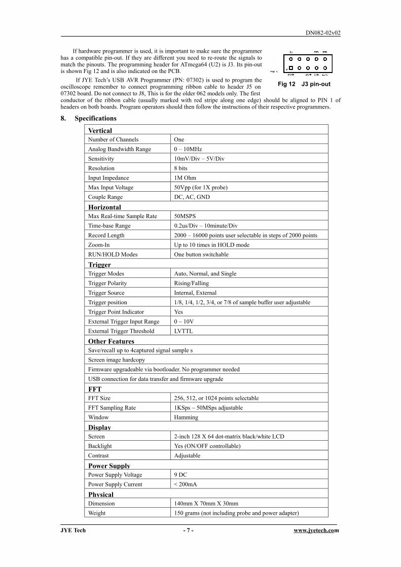
If hardware programmer is used, it is important to make sure the programmer has a compatible pin-out. If they are different you need to re-route the signals to match the pinouts. The programming header for ATmega64 (U2) is J3. Its pin-out is shown Fig 12 and is also indicated on the PCB.
If JYE Tech’s USB AVR Programmer (PN: 07302) is used to program the oscilloscope remember to connect programming ribbon cable to header J5 on 07302 board. Do not connect to J8, This is for the older 062 models only. The first conductor of the ribbon cable (usually marked with red stripe along one edge) should be aligned to PIN 1 of headers on both boards. Program operators should then follow the instructions of their respective programmers.
8. Specifications
Vertical Number of Channels One Analog Bandwidth Range 0 – 10MHz Sensitivity 10mV/Div – 5V/Div Resolution 8 bits Input Impedance 1M Ohm Max Input Voltage 50Vpp (for 1X probe) Couple Range DC, AC, GND
Horizontal Max Real-time Sample Rate 50MSPS Time-base Range 0.2us/Div – 10minute/Div Record Length 2000 – 16000 points user selectable in steps of 2000 points Zoom-In Up to 10 times in HOLD mode RUN/HOLD Modes One button switchable
Trigger Trigger Modes Auto, Normal, and Single Trigger Polarity Rising/Falling Trigger Source Internal, External Trigger position 1/8, 1/4, 1/2, 3/4, or 7/8 of sample buffer user adjustable Trigger Point Indicator Yes External Trigger Input Range 0 – 10V External Trigger Threshold LVTTL
Other Features Save/recall up to 4captured signal sample s Screen image hardcopy Firmware upgradeable via bootloader. No programmer needed USB connection for data transfer and firmware upgrade
FFT FFT Size 256, 512, or 1024 points selectable FFT Sampling Rate 1KSps – 50MSps adjustable Window Hamming
Display Screen 2-inch 128 X 64 dot-matrix black/white LCD Backlight Yes (ON/OFF controllable) Contrast Adjustable
Power Supply Power Supply Voltage 9 DC Power Supply Current < 200mA
Physical Dimension 140mm X 70mm X 30mm Weight 150 grams (not including probe and power adapter)

DN082-02v02
JYE Tech - 8 - www.jyetech.com
9 Limited Warranty JYE Tech Ltd. warrant the DSO082 oscilloscope against defects in materials and workmanship under ordinary
consumer use for a period of one year from the date of original retail purchase. During this warranty period, if a fault occurs with the oscilloscope, and the customer follows the instructions for returning the oscilloscope, We will, to the extent permitted by law, offer one of the following options: (i) repair the oscilloscope using either new or refurbished parts, (ii) replace the oscilloscope with a new or refurbished one, or (iii) refund to you, all or part of the purchase price of the oscilloscope. All replaced parts and oscilloscopes for which a refund has been given shall become the property of JYE Tech Ltd. This limited warranty applies only to the hardware components of the oscilloscope that have not been subjected to: accident, misuse, neglect, fire or other external causes, alternations, repair, or commercial use.
For information on how to obtain a warranty service for your oscilloscope, please contact JYE Tech at [email protected].
10 Revision History
Version Date Summary v01 2011.01.23 First release
v02 2011.01.25 Corrected a few typo errors