
LBL 4219 Optical Timing Receiver for the NASA Laser ... · Part I: Constant-Fraction Discriminator...
24
LBL 4219 Optical Timing Receiver for the NASA Laser Ranging System Part I: Constant-Fraction Discriminator Branko Leskovar and C. C. Lo Lawrence Berkeley Laboratory University of California Berkeley, California 94720 August 14, 197S Abstract Position-resolution capabilities of the NASA laser ranging system are essentially determined by time-resolution capabilities of its optical timing receiver. The optical timing receiver consists of a fast photoelectric device, primarily a standard of microchannel-plate-type photomulti- plier or an avalanche photodiode detector, a timing discriminator, a high-precision time-interval digitizer, and a signal-processing system. The time-resolution capabilities of the receiver are determined by the photo- electron time spread of the photoelectric device, the time walk and resolution characteristics of the timing discrimina- tor, and the time-interval digitizer. It is thus necessary to evaluate available fast photoelectronic devices with respect to their time-resolution capabilities, and to design a very low time walk timing discriminator and a high-precision time digitizer which will be used in the laser ranging system receiver. OlSTRIBv"'.'-'- H T "' ; ' -"••'-' Hi« irp«ii * i i pnpttcd (i in IIKOHM of iponmicd by Iht VMMd Stain G<miniMni S jlw tMiNtf Slim nor iht (M«l Sum iwip Rntuch mJ Dotlopiniiii AlmjnUtreiion, no! inr ol thrtr implotm, no/ my o ihtu coniuciw.. lubcnnlticlon. ol ihtk tmpluim, nukn my Wf'Wiy. » v m oi impw, «t ittyintt my tail toMtiy M i«tf«n*|baiif f M irx KciMicr, comrkitnti) OJ amumm of my taloimillon, ipjurtim.pmjuct or ptnctu dlfcluwtl, ol itpitMnli IKil 111 uw wnuld not niton* pnvaifly ownrt ii«hii,
Transcript of LBL 4219 Optical Timing Receiver for the NASA Laser ... · Part I: Constant-Fraction Discriminator...

LBL 4219
Optical Timing Receiver for the NASA Laser Ranging System Part I: Constant-Fraction Discriminator
Branko Leskovar and C. C. Lo Lawrence Berkeley Laboratory University of California
Berkeley, California 94720 August 14, 197S
Abstract Position-resolution capabilities of the NASA laser
ranging system are essentially determined by time-resolution capabilities of its optical timing receiver. The optical timing receiver consists of a fast photoelectric device, primarily a standard of microchannel-plate-type photomulti-plier or an avalanche photodiode detector, a timing discriminator, a high-precision time-interval digitizer, and a signal-processing system. The time-resolution capabilities of the receiver are determined by the photo-electron time spread of the photoelectric device, the time walk and resolution characteristics of the timing discriminator, and the time-interval digitizer. It is thus necessary to evaluate available fast photoelectronic devices with respect to their time-resolution capabilities, and to design a very low time walk timing discriminator and a high-precision time digitizer which will be used in the laser ranging system receiver.
OlSTRIBv"'.'-'- H T " ' ; ' - " • • ' - '
Hi« irp«ii * i i pnpttcd ( i in IIKOHM of iponmicd by Iht VMMd Stain G<miniMni S jlw tMiNtf Slim nor iht (M« l Sum i w i p Rntuch mJ Dotlopiniiii AlmjnUtreiion, no! inr ol thrtr implotm, no/ my o ihtu coniuciw.. lubcnnlticlon. ol ihtk tmpluim, nukn my Wf'Wiy. » v m oi impw, «t ittyintt my tail toMtiy M i«tf«n*|baiif f M irx KciMicr, comrkitnti) OJ amumm of my taloimillon, ipjurtim.pmjuct or ptnctu dlfcluwtl, ol i tp i tMnl i IKil 111 uw wnuld not niton* pnvaifly ownrt ii«hii,

Part I of this report describes the development of a modified constant-fraction discriminator which reduces amplitude-dependent timing errors to ±40 psec over a dynamic range of input pulse amplitudes from 50 mV to S V, Within the same range of input pulse amplitudes, a time resolution of 30 psec FWHM was obtained with an input signal whose rise time was 0.4 nsec and width 1.0 nsec. The unit produces 800 raV negative output pulses with pulse widths of 10 nsec, and 3 V positive pulses with pulse widths of 15 nsec. The time delay through the discriminator was approximately 32 nsec. The input signal is amplified, clipped and properly shaped by an attenuation-subtraction technique to produce a pulse with a zero-crossing point. All essential functions responsible for the discriminator timing accuracy are performed by means of tunnel diodes with backward diodes as nonlinear load. The discriminator is designed for convenient linking to a conventional time-interval unit or a high-precision time-interval digitizer. Adjustment procedure for obtaining a minimum amount of the time walk is also given.
Introduction The time-resolution capabilities of the optical timing
receiver of the NASA laser ranging system are determined by the photoelectron time spread of the photoelectric device, the time walk and resolution characteristics of the timing discriminator, and resolution capabilities of the time-interval digitizer. The stability of the system over relatively long time periods is also important.
- 2 -

Since the study of fast photoraultiplier resolution capabilities and the design of the high-precision time-interval digitizer with resolution of 10 psec will be performed at a later date in the Electronics Research and Development Group of the Lawrence Berkeley Laboratory, only high-resolution constant-fraction discriminator with picosecond time-resolution capabilities will be described in this report.
Although a number of circuits have been devised for deriving timing signals from scintillation detectors, with reduced amplitude-dependent error [1-2], our analysis and measurements have shown that the constant fraction-of-pulse-height timing, based on fast tunnel-diode circuits, is the best method for subnanosecond timing [3-4]. A modified pedestal-type constant-fraction discriminator was developed with subnanosecond time walk and resolution characteristics, in which the input signal is properly shaped by an attenuation-subtraction technique to produce a pulse with a zero-crossing point, and a pedestal added, allowing adjustment of the discriminator to the zero-crossing point. The fast baseline crossover point of a bipolar pulse is relatively independent of the pulse amplitude, and it can be conveniently used to obtain the amplitude-independent timing information. Despite the amplitude-independent crossover point of a bipolar pulse, a leading-edge detector being triggered at this point introduces a time walk, in the nanosecond region, when there is a large dynamic range of input pulse amplitude. To overcome
- 3 -
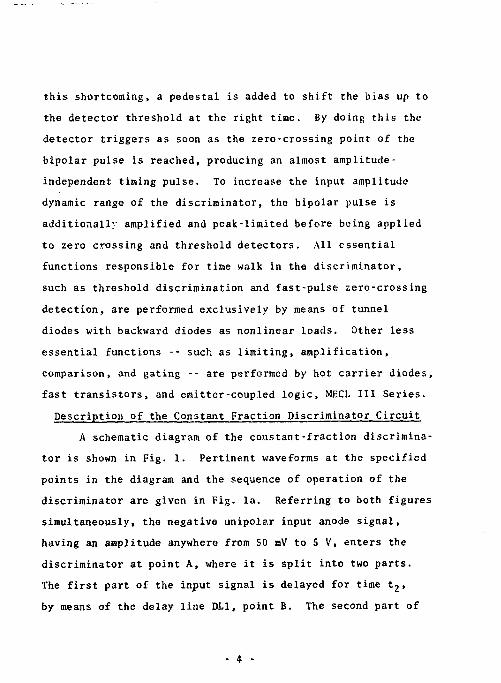
this shortcoming, a pedestal is added to shift the bias up to the detector threshold at the right time. By doing this the detector triggers as soon as the zero-crossing point of the bipolar pulse is reached, producing an almost amplitude-independent timing pulse. To increase the input amplitude dynamic range of the discriminator, the bipolar pulse is additionally amplified and peak-limited before being applied to zero crossing and threshold detectors. All essential functions responsible for time walk in the discriminator, such as threshold discrimination and fast-pulse zero-crossing detection, are performed exclusively by means of tunnel diodes with backward diodes as nonlinear loads. Other less essential functions -- such as limiting, amplification, comparison, and gating -- are performed by hot carrier diodes, fast transistors, and emitter-coupled logic, MECL III Series. Description of the Constant Fraction Discriminator Circuit
A schematic diagram of the constant-fraction discriminator is shown in Fig. 1. Pertinent waveforms at the specified points in the diagram and the sequence of operation of the discriminator are given in Fig. la. Referring to both figures simultaneously, the negative unipolar input anode signal, having an amplitude anywhere from 50 mV to 5 V, enters the discriminator at point A, where it is split into two parts. The first part of the input signal is delayed for time t 2, by means of the delay line DL1, point B. The second part of
- 4 -
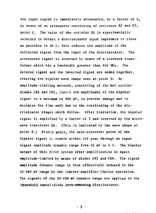
the input signal is immediately attenuated, by a factor of 5, by means of an attenuator consisting of resistors R2 and R3, point C. The value of the resistor Rl is experimentally selected to obtain a discriminator input impedance 2s close as possible to 50 ft; this reduces the amplitude of the reflected signal from the input of the discriminator. The attenuated signal is inverted by means of a wideband transformer which has a bandwidth greater than 400 MHz. The delayed signal and the inverted signal are added together, creating the bipolar wave shape seen at point D. An amplitude-limiting network, consisting of the hot carrier diodes CR1 and CR2, limits the amplitudes of the bipolar signal to a maximum of 400 mV, to prevent damage and to minimize the time walk due to the overloading of the discriminator stages which follow. After limitation, the bipolar signal is amplified by a factor of 3 and inverted by the microwave transistor Ql. (This is indicated by the wave shape at point E.) At this point, the zero-crossover point of the bipolar signal iu stable within ±15 psec through an input signal amplitude dynamic range from SO mV to 5 V. The bipolar output of this first system after amplification is again amplitude-limited by means of diodes CR3 and CR4. The signal amplitude dynamic range is thus effectively reduced to the 50-400 mV range by the limiter-amplifier-limiter operation. The signals of the 50-400 mV dynamic range are applied to the threshold tunnel-diode zero-crossing discriminator.
- 5 -

The positive portion of the bipolar pulse serves as a trigger pulse for the tunnel diode CR7 threshold detector. The peak current of this diode (C.17) is 4.7 mA. The fast-crossover slope provides better triggering for the leading -edge threshold discriminator, resulting in a pedestal with less time shift caused by wide dynamic range of the input signal pulse amplitude. When the leading-edge threshold detector was operated in this fashion the pedestal time shift was found to be approximately 500 psec better than the same detector triggering at the leading edge of the input signal pulse, over a dynamic range of 30:1. The variable resistor R19 provides a threshold adjustment for diode CR7. Inductor L8 and the backward diode CR8 serve as the nonlinear load for tunnel diode CR7. Operating a tunnel diode in this mode improves the sensitivity of the circuit and reduces its standby power dissipation. The output of this stage in turn triggers the tunnel diode CR9, which is the pedestal generator. Diode CR9 has a peak current of 10 mA. A shorting stub is the load for this stage, which generates a 25-nsec-long pedestal (point G). While this is taking place the bipolar pulse is being delayed for time tg-t- approximately 5 nsec, by the delay cable (point F) , before appearing across tunnel diode CR14, which serves as the zero-crossing detector. Diode CR14 has a peak current of 10 mA. Variable resistors R33 and R?8 provide the bias adjustment for the tunnel uiode CR14 and the pedestal generator diode CR9, respectively. The bias pedestal
- 6 -

is applied to the zero-crossing detector diode CR14 through inductor L10 and resistor R31. L10 is used to suppress the overshoot at the leading edge of the pedestal. The pedestal is used to raise the bias of CR14 nearly to its threshold level, thus reducing the trigger delay due to different slew rates of the zero-crossing pulses. The zero-crossing detector is in the form of a one-shot multivibrator, using an inductor L9 and a backward diode CR13 as a nonlinear load.
The driver stage that follows uses the tunnel diode CR17 and transformer T2 and the backward diode CR18 as its nonlinear load. Diode CR17 has a peak current of 10 mA. Variable resistor R35 provides a bias adjustment for CR17.
The driver stage output signal, at the point I, is further delayed 10 nsec (time t,-t s). This is done to allow enough time for the gating signal generated by the comparator M2, operating as a leading-edge threshold discriminator, and the gate generator, tunnel diode CRll, to be properly applied to the reference input of comparator Ml through the entire signal amplitude range, before the driving pulse arrives at Ml. Since the comparator M2 operates in the leading-edge trigger mode, the walk range of the gate signal, at point M, is approximately 5 nsec through a dynamic range of 50 mV to 5 V, or 1 to 100.
- 7 -

In order to avoid the degradation of the time walk characteristics of the discriminator as a whole, the comparator M2 is used as a lower-level discriminator which inhibits output pulses when the input signal is below a certain level. In this way the threshold level of the tunnel diode CR7 is adjusted to obtain the best possible time walk characteristic throughout the entire input pulse amplitude dynamic range, and it stays fixed at that level. The variable resistor R14 is used to set the threshold level of the comparator M2 through a voltage range from 50 mV to 500 mV. The output of comparator M2 (point K) is differentiated by the capacitor C17 and the resistor R72. The bias provided by the voltage divider formed by R7S and R76 prohibits comparator Ml from operating except when it receives a recognized input signal. The maximum driver output signal at point J is approximately -400 mV. A recognized signal at the input produces a positive pulse at point L, which triggers CR29 that serves as a buffer stage for CR11. The positive pulse generated by CR29 in turn triggers CR11, generating a gating pulse with a duration of 50 nsec, causing the comparator Ml to yield an output pulse at the MECL logic levels, "0" being -1.9 V, "1" being -0.8 V. Transistors Qr and Q, are used to convert the signal from the MECL logic levels back to the Nuclear Instrument Module (NIM) standard level, -0.8 V across 50 Q. Transistors Q 7, Q,, and Q. are used to provide an alternative positive
- 8 -

output pulse, if necessary, the width of the positive output pulse can be lengthened by using a pulse standardizer or a retriggerable one-shot multivibrator. Transistors Q7-Q12 are used to provide three more NIM outputs, making a total of four NIM outputs and one +3 V output. The transit time (the time between an input signal pulte and the output pulse) of the discrininator is approximately 32 nsec, and the transit time difference between the four NIM outputs is within ±150 psec. For high-precision measurements the same output should be used accordingly throughout the whole experiment.
Time Walk and Resolution Characteristics of the Constant-Fraction Discriminator
The time walk and resolution characteristics of the constant-fraction discriminator, as a function of the input pulse amplitude, were measured with the input pulse rise time and width as parameters. Measurements were made using the system illustrated in Fig. 2. Essentially, the source of the discriminator input pulses was a fast-rise-time pulse generator, which was combined with a step recovery diode pulse shaper when pulses with different rise times were necessary. The triggering signal from the pulse generator was applied to the external trigger terminal of a two-channel sampling oscilloscope. The output pulses from the pulse generator (pulse shaper) were applied to the constant-fraction discriminator 'hrough an 18-GHz attenuator, which has a negligible time walk for different attenuation settings.
- 9 -
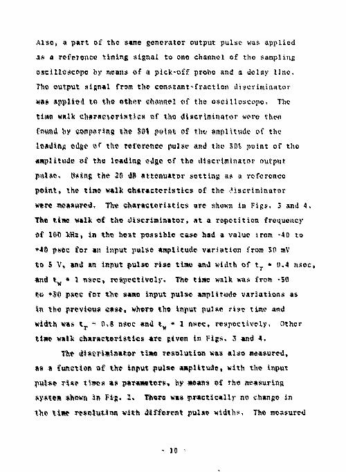
Also, a part of the same generator output pulse was applied as a reference timing signal to one channel of the sampling oscilloscope by means of a pick-off probe and a delay line. The output signal from the constant-fraction discriminator was applied to the other channel of the oscilloscope. The time walk fiharaeteristies of the discriminator were then found by comparing the SO* point of th* amplitude of the leading edge «? the reference pulse and the 50$ point of the amplitude of the leading edge of the discriminator output pulse. Using the 20 dB attenuator setting as a reference point, the time walk characteristics of the -.'.iscriminator were measured, The characteristics arc shown in Figs. 3 and 4, The time walk of the discriminator, at a repetition frequency of lot) kHs, in the best possible case had a value from -40 to •-40 psee for an input pulse amplitude variation from SO mV to S V, and an input pulse rise time and width of t r • 0,4 nsec, and t„ « I nsee, respectively. The time walk was from -SO te *50 psec for the same input pulse amplitude variations as in the previous ease, where the input pulse rise time and width was %T
s 0,8 nsec and t ¥ • 1 nsec, respectively. Other time walk 'Characteristics are given in Figs, 3 and 4,
The discriminator time resolution was also measured, as a function of the input pulse amplitude, with the input pulse rise t^wes as parameters, by means of the measuring system shown In Fig, 2, There was practically no change In the time resolution with different pulse widths. The measured
- 10 -

time resolution of the system without the constant-fraction discriminator was IS psec FWHM. Results of the measurements are given in Fig. S. It can be seen that the total system time resolution, including the constant-fraction discriminator, is 22 psoc FWHM for an input pulse amplitude variation from 300 mV to S V and for a pulso rise time and width of Q.4 and 0.8 nsec, respeetivoiy. The time resolution is 30 and 40 psoc for input rise times of 0.4 and 0.8 nsec, respectively, with input pulso amplitude of SO mV.
Operation The discriminator should be turned on for approximately
three hours before it is being tested, adjusted, or used. This time is required to stabilise the critical components in the system. Operating ambient temperature should preferably be 18-3S0 C. If possible the discriminator should be left on all the time. The voltage of the ±6 V and +12 V supplies required by the discriminator should be within 18 or better.
Adjustment During the initial tune-up the bias adjustments are
set at the optimum levels, hence drastic adjustment should not be required. However, if adjustment is needed, the system shown in Fig, 2 or an equivalent system should be used to test the discriminator. It is important to use an attenuator similar to the HP8496B and a sampling oscilloscope
-11-

similar to the Tektronix 661. Excessive walk normally occurs at the low-input-pulse amplitude range, 50-150 mV. The 50 mV point in the walk curve can be compensated by the back panel threshold adjustment (not to exceed 1 turn), and the 150 mV point can be compensated by the back panel zero-crossing adjustment (not to exceed 1 turn). The 50 and 150 mV points correspond to the 40 and 30 dB settings of tho attenuator when the input pulse amplitude is 5 V at 0 dB attenuator setting. The front panel 10-turn helipot provides a lower threshold adjustment from SO to 500 mV. Threshold level drift is less than 0.2 mV/°C in the temperature range from 18° C to 35" C. Figures 6 and 7 show the 0.4 and 0.8 nsec risetime pulses used for the testing; the pulse width in both cases is 1 nsec. Acknowledgment s
This work was performed as a part of the program of the Electronics Research and Development Group of the Lawrence Berkeley Laboratory, University of California, Berkeley, and was supported by the National Aeronautics and Space Administration - Goddard Space Flight Center, Greenbelt, Maryland.
12-

References 1. D. A. Gedge and W. J. McDonald, Design of the Constant
Fraction of Pulse Height Trigger for Optimum Time Resolution, Nucl. Instrum. Methods 58_, 2S3 (1968).
2. E. Kowalski, Nuclear Electronics (Springer-Verlag, New York, Heidelberg, Berlin, 1970), p. 179.
3. C. C, Lo and B. Leskovar, A Measuring System for Studying the Time-resolution Capabilities of Fast Photomultipliers, IUKK Trans. Nucl. Sci. NS-21, No. 1, 93-105 [1974).
4. B, Leskovar and C. C. Lo, Single Photoelectron Time Spread Measurement of Fast Photomultipliers, Nucl. Instrum, Methods ITS, 145-160 (1975).
-13-

Figure Captions Fig, 1. Schematic diagram of the constant fraction
discriminator. Fig. la. Waveforms at the particular points in the constant
fraction discriminator of Fig. 1. Fig. 2. Block diagram of the measuring system. M g . 3. Time walk characteristic of the constant-fraction
discriminator as a function of input pulse amplitude with input pulse risetime of 0.4 nsec and pulse width as parameters.
Fig. 4. Time walk characteristic of the constant-fraction
discriminator as a function of input pulse amplitude with input pulse risetime of 0.8 nsec and pulse width as parameters.
Fig. S. Discriminator time-resolution characteristics as a function of the input pulse amplitude with output pulse risetime and width as parameters.
Fig. 6. Input signal test pulse with 0.4 nsec risetime. Fig. 7. Input signal test pulse with 0.8 nsec risetime. Fig. 8a. Front panel of the constant-fraction discriminator. Fig. 8b. Rear panel of the constant-fraction discriminator. Fig. 9. Right side view of the discriminator. Fig. 10, Left side view of the discriminator.
-14-

3 * S | s j m & lip .
• is .

THRESHOLD DUCKININATO* OUTPUT
*=H- ffl DIFFERENTIATED LEADING EDGE THRESHOLD ^ DISCRIMINATOR OUTPUT
^ V I % OUTPUT DRIVER GATING PULSE
„*„, U ""»—J ® CONSTANT FRACTION DISCRIMINATOR ^ OUTPUT
xm. Tr>K-i!i7i
- 1 6 -

HP215A PULSE
GENERATOR
X TEKTRON TEKTRONIX VPl PICK OFF WITH P6034 PROBE
I
DELAY LINE
STEP RECOVERY DIODE PULSE SHAPER
FOR 0.8nttc RISE TIME
PULSES I
INTEGRATOR
I
WIDEBAND ATTENUATOR
HP8496B OR EQUIVALENT
SAMPLING SCOPE
LBL CONSTANT FRACTION
DISCRIMINATOR
o CHANNEL 1
CHANNEL 2 $£%£•
FIG. 2
- 1 7 -

0.4
0.3
?? 0 . 2 -
LBL 10X2221P-1 (NASA) CONSTANT FRACTION DISCRIMINATOR
INPUT PULSE REPETITION FREQUENCY: lOOKHz
INPUT PULSE RISE TIME t r = 0.4nt«c
3 UJ
0.1
0
-0.1 -
t » = 2llMC
-0.2
-0.3 ± I
0.02 4 6 8 4 6 8 0.1 ' " " " 1 INPUT PULSE AMPLITUDE (V)
4 6
Fie. 3
10 20 \ » i ::>s I'M.s

0.4
0.3
^ 0.2
*
* 0.1 < * 0 UJ
z p - 0 . 1
-0.2
LBL 10X 2221 P-1 (NASA) CONSTANT FRACTION DISCRIMINATOR
INPUT PULSE REPETITION FREQUENCY: lOOKHz INPUT PULSE RISE TIME t r = 0.8ntec
t „ = I O H M C
In««c. 2n*tc
-0.3 0.02 +Hrt i i i i
4 6 8 0.1 " - " " 1 INPUT PULSE AMPLITUDE (V)
Hr++i 10 20
FIG. 4

-02-
CONSTANT FRACTION DISCRIMINATOR TIME RESOLUTION FWHM (nsec)
© 2
2
•o C r-v> 2 m
a « >
O m
++ ++
f
o X
> a o z (A H >
l i i i II 4

E e M
XBBTM-6M7 « • . . * '
.«!«

S£
PEDESTAL
-R19
-R28
R33
R35
PG«
FIG. 8B
XBB 758-5969A
- 23 -

a
- M *

-25-


