LBI-38662C - EDACS CONSOLE ELECTRONICS CONTROLLER (CEC) and
38
LBI-38662C Mobile Communications EDACS TM CONSOLE ELECTRONICS CONTROLLER (CEC) and INTEGRATED MULTISITE AND CONSOLE CONTROLLER (IMC) DIGITAL AUDIO SWITCH TABLE OF CONTENTS INSTALLATION, SET-UP AND TROUBLESHOOTING....................... LBI-38938 CUSTOMER-SPECIFIC SYSTEM DOCUMENTATION OVERVIEW ..LBI-38939 CARD CAGE AND BACKPLANE ASSEMBLY .................................... LBI-38663 AUDIO BOARD...................................................................................... LBI-38664 CONTROLLER BOARD......................................................................... LBI-38667 CLOCK BOARD ..................................................................................... LBI-38668 TERMINATOR BOARD ......................................................................... LBI-38669 CONVENTIONAL INTERFACE BOARD .............................................. LBI-38774 DATA CONCENTRATOR CARD .......................................................... LBI-38868 AUDIO CONCENTRATOR CARD......................................................... LBI-38869 MOM CONCENTRATOR CARD ........................................................... LBI-38870 AUDIO AUX I/O CONCENTRATOR CARD ......................................... LBI-38871 AUX I/O CONCENTRATOR CARD....................................................... LBI-38872 CONVENTIONAL CONCENTRATOR CARD....................................... LBI-38883 AUDIO RELAY CONCENTRATOR CARD ........................................... LBI-38884 POWER SUPPLY.................................................................................... LBI-38670 AC OUTLET STRIP................................................................................ LBI-4841 CABINET FAN ASSEMBLY.................................................................. LBI-4842 Maintenance Manual
Transcript of LBI-38662C - EDACS CONSOLE ELECTRONICS CONTROLLER (CEC) and
LBI-38662C
Mobile Communications
EDACSTM
CONSOLE ELECTRONICSCONTROLLER (CEC) andINTEGRATED MULTISITE ANDCONSOLE CONTROLLER (IMC)DIGITAL AUDIO SWITCH
TABLE OF CONTENTS
INSTALLATION, SET-UP AND TROUBLESHOOTING.......................LBI-38938CUSTOMER-SPECIFIC SYSTEM DOCUMENTATION OVERVIEW ..LBI-38939CARD CAGE AND BACKPLANE ASSEMBLY....................................LBI-38663AUDIO BOARD......................................................................................LBI-38664CONTROLLER BOARD.........................................................................LBI-38667CLOCK BOARD.....................................................................................LBI-38668TERMINATOR BOARD.........................................................................LBI-38669CONVENTIONAL INTERFACE BOARD..............................................LBI-38774DATA CONCENTRATOR CARD..........................................................LBI-38868AUDIO CONCENTRATOR CARD.........................................................LBI-38869MOM CONCENTRATOR CARD...........................................................LBI-38870AUDIO AUX I/O CONCENTRATOR CARD.........................................LBI-38871AUX I/O CONCENTRATOR CARD.......................................................LBI-38872CONVENTIONAL CONCENTRATOR CARD.......................................LBI-38883AUDIO RELAY CONCENTRATOR CARD...........................................LBI-38884POWER SUPPLY....................................................................................LBI-38670AC OUTLET STRIP................................................................................LBI-4841CABINET FAN ASSEMBLY..................................................................LBI-4842
Maintenance Manual

LBI-38662
TABLE OF CONTENTSPage
SPECIFICATIONS ............................................................................................................................ 3INTRODUCTION ............................................................................................................................. 5
MULTISITE COMMUNICATION ........................................................................................... 5DISPATCH CONSOLE COMMUNICATION .......................................................................... 6
DESCRIPTION ................................................................................................................................. 6SYSTEM MANAGER ................................................................................................................ 6CEC/IMC MANAGER (MOM PC) ........................................................................................... 6PRIMARY HARDWARE COMPONENTS .............................................................................. 7
Card Cage And Backplane Assembly..................................................................................... 7Audio Board.......................................................................................................................... 7Controller Board .................................................................................................................... 7Clock Board........................................................................................................................... 8Terminator Board .................................................................................................................. 8Conventional Interface Board................................................................................................. 9Concentrator Cards ................................................................................................................ 9Redundant Power Supply (RPS) Units.................................................................................... 9
CEC/IMC INTERFACE MODULES ........................................................................................ 9MASTR II/III Interface Module (MIM).................................................................................. 10Console Interface Module (CIM)............................................................................................ 10C3 Console Translator (XLTR).............................................................................................. 10ConVentional Interface Module (VMIM) And Conventional Interface Adapter (CIA) Rack ... 11Monitor Module (MOM)........................................................................................................ 11Request Status Monitor Interface Module (RIM).................................................................... 11Centralized Activity Module (CAM)...................................................................................... 11Network Interface Module (NIM)........................................................................................... 11Centralized Telephone Interconnect Module (CTIM) ............................................................. 12EDACS Data Gateway Interface Module (DATA).................................................................. 12Digital Voice Interface Module (DVIM)................................................................................. 12Logging Recorder Interface Module (LRIM).......................................................................... 12
CEC/IMC CABINET RACK-UP SUMMARY .......................................................................... 13CEC/IMC Switch Cabinets.................................................................................................... 13GETC Uplink Cabinets .......................................................................................................... 13DVIU Cabinets...................................................................................................................... 13
DISTRIBUTED ARCHITECTURE ADVANTAGES ...................................................................... 13OPERATION DURING FAILURE OF AN INTERFACE MODULE ..................................... 14FASTER DATA TRANSFERS................................................................................................... 14EXPANSION AND SERVICE CAPABILITY ........................................................................... 14
GLOSSARY....................................................................................................................................... 15ILLUSTRATIONS
Figure 1 - Typical IMC Network............................................................................................ 5Figure 2 - CEC/IMC Architecture .......................................................................................... 18Figure 3 - Interface Module Architecture............................................................................... 20Figure 4 - Controller Board Architecture................................................................................ 20
APPLICATION ASSEMBLY DIAGRAMSCEC/IMC SWITCH CABINET (3 Sheets)................................................................................. 21GETC UPLINK CABINET (2 Sheets)........................................................................................ 24DVIU CABINET (2 Sheets)......................................................................................................... 26
CABLE ASSEMBLY DIAGRAMS .................................................................................................. 28
Copyright© November 1991, Ericsson GE Mobile Communications, Inc.
2

LBI-38662
SPECIFICATIONS*FEATURES
Primary DesignControl Type Multiple distributed microprocessorsAudio Processing Pulse Code Modulation; 64k baud mu-law quantizationAudio Switching Time Division Multiplexed bus system
System Reliability •• Single-point failure tolerant
• Redundant options available for key modules• Redundant high-speed data bus with tri-state devices• Informational, warning and error messages displayed on
CEC/IMC Manager (MOM PC)• LED indicators on each board provide indications of
current board status for quick troubleshooting anddiagnostic checks
CEC/IMC Manager Functions • Reconfigure CEC/IMC on-line with no service interruption
• Program console parameters and permission lists on-line• Interface with EDACS System Manager to automatically
download database changesGENERAL
Regulatory DataComplete System Meets FCC Part 15Power Supply Meets UL, CSA and IEC 950 electrical safety standards
Maximum CapacitiesCard Cages (racks) 8 (6 CEC/IMC and 2 CIA)Audio Ports 240 full duplex plus logging recorder and console unselect
speaker outputsIMC EDACS & CNI Systems (up to 20 chan. each) 28CEC EDACS & CNI Systems (up to 20 chan. each) 6 (1 EDACS plus 5 CNI systems)CTIS (up to 20 ports) 1EDACS Data Gateway Interface (up to 8 ports) 1EDACS Network Interface (up to 24 ports) 1 (32 for StarGate Controller)Dispatch Consoles 30Conventional Channels 64Digital Voice Channels 120Logging Recorder Outputs 128
Cabinet CharacteristicsDimensions (height x width x depth) 69 1/16 x 24 x 24 inches (175.5 x 61 x 61 centimeters)Material 16-gauge cold rolled steelColor Light gray with black trim
EnvironmentalTemperature Ranges
Operating 0 to +40°CNon-Operating -20 to +85°C
Maximum Humidity 95% non-condensingElectro-Magnetic Interference (EMI) Conforms to FCC Part 15 Class A, EN55022 Class AUninterruptible Power Supply (UPS) Recommended
Processing SpeedsCall Routing Time Less than 10 millisecondsMultisite Access Time Less than 500 milliseconds
* These specifications are intended primarily for the use of the serviceman. See the appropriate Specifications Sheet for complete specifications.
3

LBI-38662
Dispatch Console LinkLocal Connection 4000 feet maximum using at least a 5-pair cableRemote Connection User provided private or leased facilities and data modems
Auxiliary Inputs And OutputsAuxiliary Inputs Opto-isolated, balanced input
Impedance 1200 ohms (approximate)Current 5 mA nominal, 10 mA maximum
Auxiliary Outputs Form-A and open-collectorVoltage Rating 24 Volts ac or dc (Form-A); 50 Vdc (open-collector)Current Rating 1 Amp, non-inductive load (Form-A); 20 mA
(open-collector)Redundant Power Supply (per Card Cage)
Input Voltage 120 Vac ±15% or 230 Vac ±15% (47 to 63 Hz)Input Voltage Selection Automatic (no configuration necessary)Input Power 580 Watts maximum at full dc loadDC Outputs +5 Vdc, +15 Vdc and -15 VdcTotal Output Power 380 Watts maximumDuty Cycle ContinuousOutput Hold-Up Time 20 milliseconds under full loadStatus Indicators All outputs OK and over-temperatureRedundancy Dual-module design with "n+1" redundancyOver-Voltage Protection +5 Vdc output will not exceed 6.5 Vdc ±0.75 Vdc and
+15 Vdc output will not exceed 18.0 Vdc ±1.0 VdcShort-Circuit Protection Primary power and primary current limitingReverse Voltage Protection ProvidedThermal Protection Thermal overload protection enabled at 80°CElectrical Safety Standards Meets UL, CSA and IEC 950 standards
UPS RecommendationsRating 600 Watts minimum per Card Cage (rack)Hold-Up Time until generator (customer supplied) can be brought on-line
END-TO-END SPECIFICATIONSAudio Performance
Frequency Response ±3 dB from 300 to 3000 HzDistortion Less than 3% from 300 to 3000 HzHum And Noise
Transmit 50 dB below rated outputReceive 50 dB below 1 Watt speaker output
Input/Output Level Control Digital Level Memory (DLM) - gain level stored in digitalmemory
Input Range -25 to +12 dBm (adjustable via DLM)Output Range -25 to +10 dBm (adjustable via DLM)Gain Performance Will not increase in the presence of noise or absence of voice
with Automatic Level Control (ALC) disabledInput/Output Impedance 600 ohms ±10%, balanced line
Control Data LinksLocal Connection 9.6k or 19.2k baud RS-232C connectionRemote Connection Type 3002 data-grade phone line or equivalent required
Conventional Base Station ControlsGeneral 2-wire or 4-wire connectionTone Control Signaling 11 EIA standard function tones from 1050 to 2050 HzDC Control Signaling 0, -2.5, ±6 and ±11 mA (135 Vdc maximum)Hold Tone Dynamic Range -45 to -20 dBmE & M Signaling Provided
4

LBI-38662
INTRODUCTIONThe Ericsson GE EDACSTM Integrated Multisite and
Console Controller (IMC ) is a digital audio switch thatroutes audio, mobile data and Aegis data between EDACSradio systems and dispatch consoles. The IMC supportsanalog voice, digital data, digital voice and encrypted voicethroughout the wide area network and dispatch consolesystems.
The EDACSTM Console Electronics Controller (CEC)is based on the same hardware platform as the IMC. Unlikethe IMC, the CEC does not perform multisite trunked radiofunctions. The CEC does offer sophisticated dispatchconsole features and it can be considered a subset of theIMC. The common hardware of the CEC and IMC digitalaudio switch has previously been referred to as the"MultiSite Coordinator II " (MSC II ).
The CEC/IMC switch is designed in a distributedarchitectural fashion. This design greatly improvesreliability and performance.
Wide-area network communication is accomplished byswitching audio, mobile data and Aegis data connectionsbetween EDACS radio systems and dispatch consoles usingstate-of-the-art digital audio switching technology. Theflexible design of the network switch allows interfacing toall EDACS levels from Basic EDACS to EDACS Level 4,
including simulcast and other multisite network switches.The network switch is also capable of being interfaced toconventional radio systems.
MULTISITE COMMUNICATION
The IMC allows communications between two-wayradios located in different geographical areas. Figure 1shows a simplified example of a typical IMC network. Thismultiple-site trunked repeater network has three (3)repeater systems (EDACS sites in this example) labeled S1,S2 and S3. Each system provides communications for itsarea: A1, A2 and A3 respectively. Multisite communicationoccurs when a unit in one area − for example Unit 1 in A1 − communicates with a unit in a different area − forexample Unit 2 in A2.
Unit 1's operator initiates a call to Unit 2 by pressingthe mobile radio's Push-To-Talk (PTT) button. The RFworking channel request is then transmitted to S1 on thesite's RF control channel. Each EDACS site continuouslymonitors its control channel for call initiations. When a callis initiated, the site assigns a working channel to the callingradio by instructing it to switch from the control channel tothe assigned working channel. This working channel isassigned via the site's control channel and it is applicableonly in the area (A1 in this example) covered by theprimary site (S1).
UNIT 2UNIT 1
S1 S2
A1 A2
A3
S3
DIGITALAUDIO
SWITCH
IMC
Figure 1 - Typical IMC Network
5

LBI-38662
The primary site also sends the working channelassignment information to the IMC network switch via thedownlink control data channel. At this time the IMCassigns an internal digital audio slot to the call and it thensends a channel request to the secondary site (S2 in thisexample). When the secondary site receives the channelrequest from the IMC, it assigns a secondary RF workingchannel for the call. This working channel is assigned toUnit 2 via the secondary site's control channel and it is onlyvalid in the area covered by the secondary site. Thesecondary site also sends the secondary working channelassignment information back to the IMC. Unit 1 in A1 cannow effectively communicate with Unit 2 in A2 via theIMC network switch.
To summarize, the call from the mobile radio isinitially transmitted to the primary site, routed through theassigned digital audio slot in the IMC, and thenretransmitted by the secondary site to the mobile receivingunit.
When the calling radio ends the call (releases PTT),the primary site deactivates the assigned primary workingchannel for the call and notifies the IMC that the call hasbeen terminated. The IMC then releases the assigneddigital audio slot and sends an "end-of-call" command tothe secondary site. This "end-of-call" command instructsthe secondary site to release the secondary workingchannel.
In a multisite network, all EDACS radio units aregiven a unique logical identification (LID) number that isvalid throughout the entire network. This allows thenetwork to not only control group and individual calls, butto also track individual radio units as they move fromsystem-to-system. A radio programmed for automatic loginoperation will be automatically tracked when it moves to anew system. If the radio is not programmed for automaticlogin, the operator must press the PTT button before it willlog into a new system.
DISPATCH CONSOLE COMMUNICATION
Both the CEC and IMC equipment allowcommunications between dispatchers located in differentareas and between dispatchers and mobile/portable radiounits located in different areas. Dispatch consoles areconnected to the network switch in a similar manner as theEDACS radio systems and they issue call requests to it in asimilar manner.
When a call is made from a mobile or portable radiounit, the switch informs the dispatch consoles and EDACSradio system(s) of the call. This allows a particular dispatchconsole in the CEC/IMC network to participate in any talkgroup conversation that it can monitor.
DESCRIPTIONFigure 2 shows the hardware components that form a
typical CEC/IMC digital audio switch. Most of thecomponents form "interface modules" that allow theCEC/IMC switch to transfer audio, mobile data and Aegisdata between the radio systems and dispatch consoleslinked to the switch. Each interface module is made fromone or more printed circuit boards. A basic overview ofeach board is described in the section entitled "PRIMARYHARDWARE COMPONENTS ". Also see the sectionentitled "CEC/IMC INTERFACE MODULES " forspecific interface-level details.
SYSTEM MANAGER
The System Manager contains a common database formultisite network operations. This database stores systemand user data for all systems within the CEC/IMC network.Pertinent database information used to control the multisiteequipment is downloaded from the System Manager intothe CEC/IMC network switch. Group ID, unit ID, and aliasinformation is forwarded to all dispatch positions for calldisplay purposes. This eliminates the need for separateentry and maintenance of this information at the dispatchpositions.
If the System Manager is co-located, it is connected tothe network switch via a 19.2k baud RS-232 serial interfaceprovided by the MOnitor Module (MOM ) interfacemodule. A remote System Manager-to-CEC/IMCconnection also requires a modem at both locationsoperating at 9.6k or 19.2k baud.
CEC/IMC MANAGER (MOM PC)
CEC/IMC network switch monitoring andconfiguration functions are provided by the CEC/IMCManager. This IBM PC compatible computer runningcustom software developed by Ericsson GE was previouslyreferred to as the "MOnitor Module Personal Computer"(MOM PC ). It is the window into the CEC/IMC networkswitch for both the system administrator and the servicetechnicians. Detailed operating procedures for theCEC/IMC Manager (MOM PC) are contained in LBI-38911. The following list highlights some of the featuresprovided by the CEC/IMC Manager:
• view system configuration
• view interface module (MIM, CIM, VMIM, etc.)statistics
• view Global Serial Channel (GSC) loading
• configure Time Division Multiplexed (TDM )audio bus slots
6
LBI-38662
• configure console profiles with up to ten (10) shiftsper console
• configure C3 Modular/Desktop consoles
• configure trunked channel audio levels
• configure conventional channel audio levels
• configure MOnitor Module (MOM ) interfacemodule
• connects to System Manager to obtain unit, groupand system databases
• set CEC/IMC time and date (WWVB timesynchronization option available)
The CEC/IMC Manager is also connected to thenetwork switch by an 19.2k baud RS-232 serial linkprovided by the MOM interface module.
PRIMARY HARDWARE COMPONENTS
Card Cage And Backplane Assembly
The Card Cage and Backplane Assemblies furnishhousing and electrical interconnections for all of theprimary printed circuit boards used in the network switch.These 6-rack unit assemblies are typically called "CardCages" or "racks". Each one has twenty-one (21) physicalslots for board insertion.
A fully-loaded CEC/IMC network switch contains six(6) primary Card Cages installed in two (2) side-by-sidecabinets and a third cabinet which houses two (2)Conventional Interface Adapter (CIA ) Card Cages.Alternately, both CIA Card Cages may be housed in thesame cabinet as the primary Card Cages if the switchcontains four (4) or less primary Card Cages. See thesection in this manual entitled "CEC/IMC CABINETRACK-UP SUMMARY " for additional details.
All Backplanes (except the CIA racks) areinterconnected or "daisy-chained" together using multi-conductor ribbon cable pairs referred to as "intra-rack" and"inter-rack" cables. This daisy-chain design joins the digitalbuses (TDM, GSC, etc.) between all Backplanes in allprimary Card Cages. Intra-rack cables join the Backplanesin an individual cabinet together and inter-rack cables jointhe Backplanes between cabinets in a dual-cabinetinstallation.
Audio Board
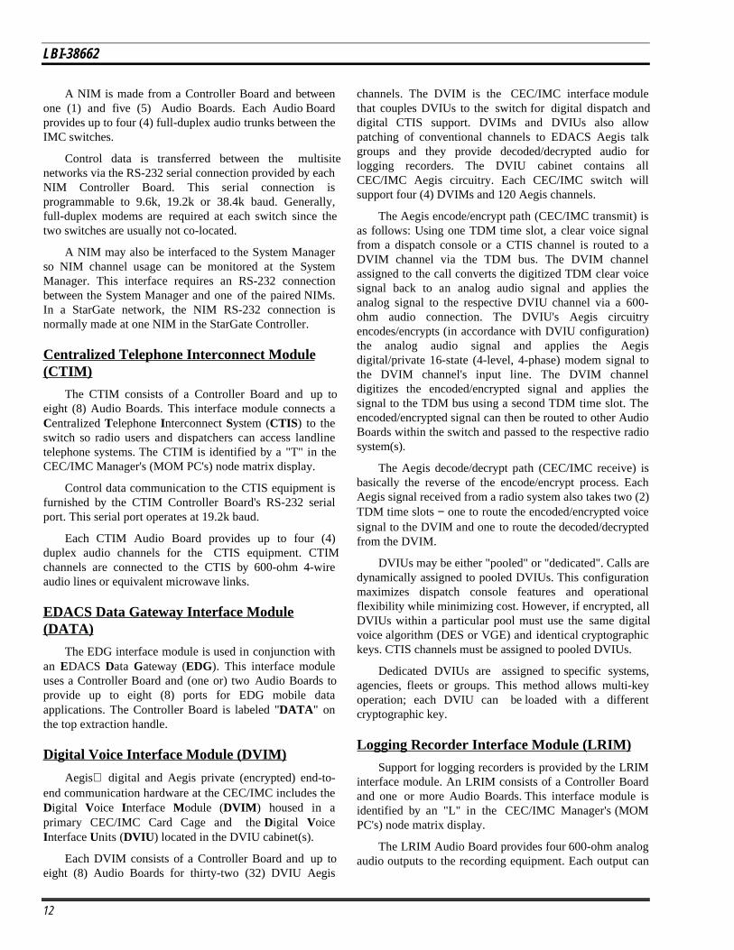
The Audio Board links audio, mobile data and Aegisdata between EDACS radio systems, consoles, or otherexternal devices and the Time Division Multiplexed(TDM ) audio network. This TDM audio network digitally
transfers voice audio between the Audio Boards within thenetwork switch. It can also transfer mobile data and Aegismodem signals. These modem signals are 16-state (4-level,4-phase) quadrature amplitude modulated signals that havean effective baud rate of 9.6k.
An Audio Board can provide up to four (4) full-duplex4-wire audio links or "channels" into and out of thenetwork switch for its respective interface module. Eachchannel's audio processing circuitry converts incomingsource analog audio/modem signals (from the radio systemor console) into digitized signals. The digitized signals arethen selectively applied to the TDM audio network. Eachchannel also incorporates audio processing circuitry thatextracts selected digitized destination audio/modem signals(to the radio system or console) from the TDM audionetwork and converts the digitized audio/modem signalsback to analog audio/modem signals. The transmit andreceive audio processing circuitry uses mu-law Pulse CodeModulation (PCM) processing technology incorporatedwithin COder-DECoder (CODEC) chips. The AudioBoards process voice and modem signals identically; thetype of signal is transparent to the board.
The TDM audio network is formed by eight (8) TDMaudio buses. Each bus has 32 multiplexed time slots thatcarry a single audio channel. Sixteen (16) time slots arereserved. This design allows simultaneous routing of up to240 channels through the network switch. 8 buses x 32slots = 256 total slots - 16 reserved slots = 240 availableslots.
An on-board 80C535 microprocessor controls most ofthe Audio Board's functions. However, the ControllerBoard provides master Audio Board control via parallel I/Oand high-speed HDLC serial data connections. Basic audiorouting is controlled by the parallel I/O connections fromthe Controller Board and the HDLC serial link controlsnon-critical functions such as tone generation (alert, grant,etc.) and notch filter enabling.
Audio Boards are labeled "AUDIO " on their topextraction handle. They are labeled in accordance withtheir assigned channels on their bottom extraction handle.For example, an Audio Board assigned to channels 5 - 8 islabeled "05 - 08" on its bottom handle. See LBI-38664 fordetailed Audio Board service information.
Controller Board
Each CEC/IMC interface module is supported by amicroprocessor-controlled communications ControllerBoard. The Controller Board contains a set of unique"interface module" software personalities. Each softwarepersonality is designed to interface a particular externaldevice to the CEC/IMC switch. For example, onepersonality known as a "MIM" interfaces an EDACS radio
7

LBI-38662
system to the switch and another personality know as a"CIM" interfaces a console to the switch. Personalityselection is accomplished with DIP switches on theController Board. See the section entitled "CEC/IMCINTERFACE MODULES " for further details on theinterface modules.
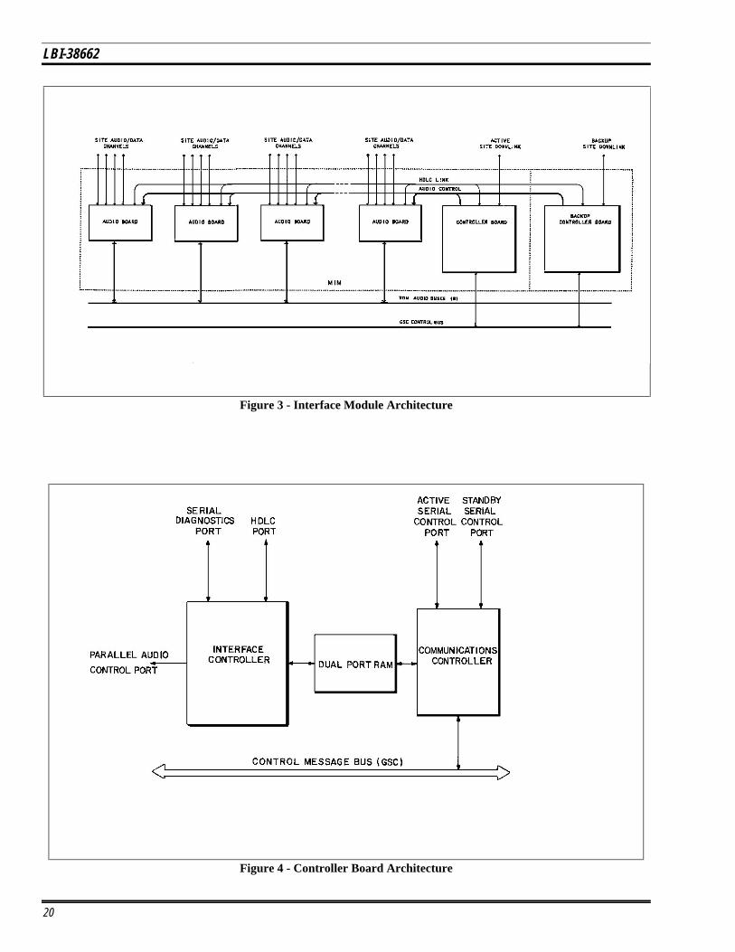
As shown in Figures 2 through 4, a Controller Boardroutes messages and control information between itsassociated Audio Board(s), the external devices connectedto it and/or other Controller Boards within the networkswitch.
An Intel 80C152 microprocessor on the ControllerBoard is the "communications controller" for its interfacemodule. Within the network switch, a high-speed GlobalSerial Channel (GSC) control bus links all ControllerBoards' 80C152s together enabling control data to betransferred between the boards. This GSC bus utilizes thePeerless CSMA/CD local area network protocol to transfercontrol data. The 80C152 directly controls two RS-232/RS-422 serial ports that connect the Controller Board toexternal devices such as a Site Controller (via an uplinkGETC) or a CRT console.
The Controller Board also has an Intel 80C186microprocessor. Dual-Port RAM (DPRAM ) chips are usedto transfer data between the two processors. The 80C186microprocessor is the "interface controller" that performsmost I/O functions and logical processing for its respectiveinterface module. It switches the audio network byassigning time slots to active channels. This Audio Boardcontrol is accomplished using the high-speed HDLC serialdata link and two 8-bit parallel I/O ports that interconnectthe Controller Board to its respective Audio Board(s).
The 80C186 controls two dual HDLC serialcommunication controller chips on the board. One HDLCchip provides a full-duplex RS-422 serial link and the otherprovides a control link to the Audio Board(s) used for non-critical Audio Board control.
Controller Boards are labeled according to theirrespective interface module on their top extraction handleand they are labeled in accordance with their respectivedevice (system) assignment number on their bottomextraction handle. For example, a MIM Controller Boardassigned to EDACS site 3 is labeled "MIM " on the tophandle and "03" on the bottom handle. See LBI-38667 fordetailed Controller Board configuration and serviceinformation.
Clock Board
The Clock Board generates synchronized clock pulsesfor the TDM audio network. These pulses, applied to theAudio Boards via FUTUREBUS lines on the Backplane,
define time slots in which the digitized audio/modemsignals are read and written to the eight (8) TDM audiobuses. Two (2) identical but completely separate clockcircuits − "A" and "B" − on each Clock Board provideredundant (back-up) clocking capability. Clock pulseoutputs from both circuits are applied to the Audio Boardsvia the on-board FUTUREBUS transceivers and theBackplane(s).
Automatic redundant clock switch-over selection iscontrolled by the MOM Controller Board (See "CEC/IMCINTERFACE MODULES " for MOM details). The initialstart-up or default clock circuit is "B". If the "B" clock fails,the MOM will automatically select the "A" clock circuit.This redundant clock circuit selection can be enabled anddisabled via the CEC/IMC Manager (MOM PC).
Clock monitoring circuitry on the Audio Boards signalthe MOM Controller if any of the selected clock pulses fail.This alarm signal is sent to the respective Controller Boardvia the local control bus and the Controller Board thensignals the MOM Controller Board via the GSC bus.
Panel-mounted toggle switches on the Clock Boardsallow independent enable/disable control of theFUTUREBUS transceivers so multiple Clock Boards can beinstalled. Generally, two (2) Clock Boards are installed perCEC/IMC switch so uninterruptible operation can beachieved when a single Clock Board must be removed forservicing. All audio, mobile data and Aegis data linkswould be lost if the selected Clock Board was removed forservice. Clock Boards are normally installed in the outer-most slots of the center Card Cage. For example, in a three(3) Card Cage (rack) network switch, Clock Boards areinstalled in the far left and far right positions of the middleCard Cage. See LBI-38668 for detailed Clock Board serviceinformation.
Terminator Board
The Terminator Board used in the CEC/IMC switchprovides line termination for the FUTUREBUS lines on theBackplanes. These lines include the TDM audio buses, theGSC control bus and the clock lines. Two (2) TerminatorBoards are required per "daisy-chain" Backplane set. One isinstalled on each end of the chain.
The CIA racks are not daisy-chained together.Therefore, each CIA rack requires two (2) TerminatorBoards − one is installed on each end of a rack's Backplane.
Each Terminator Board has sixty-three 39-ohm pull-upresistors, with each resistor pulling its line to a 2-voltregulated supply. The design includes a primary andsecondary 2-volt regulated supply with the secondarysupply providing back-up operation if the primary regulatorfails. Relay alarm outputs are provided for both the primary
8

LBI-38662
and the secondary regulators. See LBI-38669 for detailedservice information on the Terminator Board.
Conventional Interface Board
Control signal generation and audio exchange forconventional base stations and conventional analog satellitereceivers is furnished by the Conventional Interface (CI )Board. This board is a part of the Conventional InterfaceAdapter (CIA ) rack. The CIA rack is considered asecondary interface because it does not have direct TDMand GSC bus links to the primary CEC/IMC interfacemodules. Each CIA rack is connected to a VMIM interfacemodule via 600-ohm audio connections and an RS-232serial control data connection. The VMIM is located in oneof the primary CEC/IMC Card Cages.
The CI Board provides four (4) duplex audio channellinks for conventional equipment. Eight (8) CI Boards maybe included in each CIA rack for a total of thirty-two (32)4-wire conventional channel links per CIA - VMIM set.Two (2) VMIM - CIA sets may be used per CEC/IMCswitch to link up to sixty-four (64) conventional stations tothe switch. See the section entitled "CEC/IMCINTERFACE MODULES " for further details on interfacemodules.
Every CI Board channel has control signal generationcircuitry that can be programmed via the CEC/IMCManager (MOM PC) for either tone or dc signalling.Transmit audio signals from the Audio Board within theVMIM are summed with the control signal generated onthe CI Board (either tone or dc) and the summed signal ispassed to the conventional base station via the phone line.E & M signaling capability is provided for microwave (orequivalent) connections.
Voice-Operated (VOX ) and Carrier Operated Relay(COR) detection circuitry is incorporated into eachconventional channel for receive audio detection. VOX orCOR operation is selected on a per channel basis by theCEC/IMC Manager (MOM PC). When receive audio froma base station (or voter) is detected the CIA signals theVMIM of the call. The CI Board transfers receive audiofrom the base station (or voter) to the respective channelwithin the VMIM.
An Intel 80C152 microprocessor furnishes control forthe CI Board. It links the CI Board to the CCI ControllerBoard using a local GSC control bus. See LBI-38774 fordetailed service information on the Conventional InterfaceBoard.
Concentrator Cards
Concentrator Cards, mounted on the hinged horizontalpanels on the rear cabinet rails, simplify connections to the
CEC/IMC network switch. All of the cards, except theCEC/IMC Manager (MOM PC) Concentrator Card,convert/interconnect pairs of 24-pin dual-row headerconnectors on the Backplane to 50-pin Champ-typeconnectors on the card. The Champ connectors are thencoupled to standard punch blocks (or other signal break-outdevices) using 25-pair cables. Many signals can be neatlyrouted between the network switch and punch blocks usingthe Concentrator Cards.
Each MOM Concentrator Card converts/interconnectsa 24-pin dual-row header connector at the MOM interfacemodule Backplane point into two (2) DB-9 connectors. TheCEC/IMC Manager (MOM PC) and the System Managerare then individually coupled to the MOM interface moduleby the RS-232 serial port provided at each DB-9 connector.
Redundant Power Supply (RPS) Units
Operating power for the network switch is provided by380-Watt Redundant Power Supply (RPS) units mountedin the lower-most positions in each cabinet. Each RPS unitoccupies three rack units (5.25 inches) in the standard 19-inch rack mount cabinet. There is an RPS unit for everycard cage assembly (maximum of three per cabinet).
Each RPS unit delivers +5, +15 and -15 Vdc power tothe Backplane from dual independent switching powersupply modules. These hot-pluggable slide-in power supplymodules feature +5 Vdc remote sensing, status indicators,automatic 120/230 Vac input line voltage selection, thermalshutdown, over-voltage protection and alarm outputs. EachRPS module also has a recessed front panel +5 Vdc outputtrimmer control.
Outputs from both power supply modules within anRPS unit are paralleled together and connected to itsrespective Backplane. Output "ORing" diodes within eachmodule eliminate catastrophic CEC/IMC switch failures ifa short develops in the output stage of a single module.Remote +5 Vdc regulator sensing built into each modulecompensates for diode and cable voltage drops in the +5Vdc line.
CEC/IMC INTERFACE MODULES
The CEC/IMC network switch is a set of "interfacemodules" which route communications between dispatchconsoles, EDACS radio systems, conventional stations andvarious other communication equipment such as telephoneinterconnect systems. The following section describes themajor interface modules which form the digital audioswitch. Also see Figures 2 through 4, and the ApplicationAssembly Diagrams at the end of this manual.
Each interface module consists of a Controller Boardand, in most cases, one or more Audio Boards. A back-up
9

LBI-38662
(standby) Controller Board may also be included within theMIM interface module. The CEC/IMC interface modulesinclude:
NOTE
The abbreviations shown in UPPER CASEBOLD text in the following list identify the labelthat is applied on the top extraction handle of theinterface module's Controller Board.
• MASTR II/III Interface Module (MIM )
• Console Interface Module (CIM )
• C3 Modular/Desktop Console Translator (XLTR )
• ConVentional MASTR II/III Interface Module(VMIM)
• Conventional Interface Adapter Rack (CIA)
• Conventional Controller Interface (CCI )
• MOnitor Module (MOM )
• Request Status Monitor Interface Module (RIM )
• Centralized Activity Module (CAM )
• Network Interface Module (NIM )
• Centralized Telephone Interconnect Module(CTIM )
• Logging Recorder Interface Module (LRIM )
• EDACS Data Gateway Interface (DATA )
• Digital Voice Interface Module (DVIM )
MASTR II/III Interface Module (MIM)
Interfacing to an EDACS radio system is accomplishedwith a MASTR II/III Interface Module (MIM ). Possibleradio system types include standard EDACS trunked sites,simulcast systems, voted systems, CNI and SCAT systems.A MIM is identified by an "M" in the CEC/IMC Manager's(MOM PC's) node matrix display. This display is a part ofthe CEC/IMC Manager's "View System / Diagnostics"screen.
The MIM consists of a Controller Board and up to five(5) Audio Boards for a 20-channel system. An optionalstandby Controller Board may be used with an EDACStrunked site for redundant downlink operation. (CNI andSCAT systems do not have redundant downlink capability.)The radio system's audio channels are supported by theMIM's Audio Board(s). Each Audio Board can support upto four (4) full-duplex audio channels to the radio system.
Each MIM Controller Board requires a GeneralElectric Trunking Card (GETC) to provide the controldata communication uplink to its respective radio systemdownlink. The GETCs are housed in separate 69-inchcabinets.
Audio Boards and the GETC uplinks are connected tothe radio system by 600-ohm phone lines or equivalentmicrowave links. GETC-to-site links require data-grade(type 3002) phone lines. Controller Boards are connected totheir respective GETCs by RS-232 serial connections whichoperate at 19.2k baud. The GETC-to-site link operates at9.6k baud using 16-state (4-level 4-phase) quadratureamplitude modulation modems built into the GETC.
Console Interface Module (CIM)
EDACS C3 Maestro and C3 Modular/Desktop dispatchconsoles are connected to the CEC/IMC network switchusing a Console Interface Module (CIM ). The CIMconsists of a Controller Board and a single Audio Board.CIMs are identified by a "C" in the CEC/IMC Manager's(MOM PC's) node matrix display. The C3 ConsoleTranslator is also required to connect a C3Modular/Desktop console to the network switch. See thefollowing section for Translator details.
The console control data link is provided by an RS-232or RS-422 connection at the Controller Board. This serialport has "auto-baud" sensing. It automatically sets itself tothe correct baud rate (9.6k or 19.2k baud) based on thebaud rate received from its respective console. If theconsole is remotely located, 9.6k baud full duplex modemsare required at both locations.
Full-duplex audio support for the console is providedby the CIM's Audio Board. Dual-speaker consoles consumetwo (2) channels: one 4-wire link for the selected speakerand mic, and a 2-wire link for the unselected speaker. Four-speaker consoles require all four Audio Board channels.
C3 Console Translator (XLTR)
The XLTR consists of a single Controller Board.Using protocol conversion techniques, this interface moduleallows the CEC/IMC network switch to communicate witha C3 Modular/Desktop console via an RS-422 serial controldata link operating at 9.6k baud. The XLTR is placed in thecontrol data path between the C3 console and its respectiveCIM. The CIM Controller Board is linked to the XLTRController Board by a 19.2k baud RS-232 connection.Audio support for the C3 console is furnished by the CIM'sAudio Board.
10

LBI-38662
ConVentional MASTR II/III Interface Module(VMIM) & Conventional Interface Adapter(CIA) Rack
The VMIM interface module and CIA secondaryinterface rack couple conventional tone or dc controlledbase stations and conventional voting systems to theCEC/IMC switch. Each VMIM - CIA set can couple a totalof 32 full-duplex (4-wire) links to the switch. A switch cansupport two (2) CIA racks providing a total of sixty-four(64) duplex conventional channel audio links.
The CIA appears to the VMIM as an EDACS radiosystem. It provides the databasing capabilities that enableconventional channels to be patched or "simul-selected" totrunked groups. Also included within the CIA is thehardware required to communicate with conventional basestations using either tone or dc control signals. E & Msignaling capability is also included to support microwave(or equivalent) links.
The VMIM is identified by a "V" in the CEC/IMCManager's (MOM PC's) node matrix display. The CIA isnot identified since it is not a primary component of aCEC/IMC switch.
A VMIM is formed by a Controller Board and up toeight (8) Audio Boards. The CIA secondary interface,located in a separate Card Cage (rack), is formed by aController Board configured as a Conventional ControlInterface (CCI ) and up to eight (8) Conventional Interface(CI ) Boards. Each CI Board is paired with a VMIM AudioBoard to provide four 600-ohm 4-wire duplex audio links toconventional stations. This design establishes the thirty-two(32) maximum channels per VMIM - CIA set. VMIMAudio Board channels are connected to the respective CIACI Board channels using 600-ohm 4-wire connections.
Control data communications between the VMIM andthe CIA is accomplished with an RS-232 serial portprovided by each interface module's Controller Board. Thiscontrol data link operates at 19.2k baud.
Monitor Module (MOM)
Control data interfacing to the System Managercomputer for system, unit and group database downloads tothe CEC/IMC switch and consoles is accomplished with theMOnitor Module (MOM ) interface module. The MOMalso interfaces to the CEC/IMC Manager (MOM PC) whichstores various centralized databases required by the networkswitch. This interface module consists of a ControllerBoard and an Audio Board. The MOM is identified by an"O" in the CEC/IMC Manager's (MOM PC's) node matrixdisplay.
Two RS-232 serial ports at the Controller Board,programmable to 9.6k or 19.2k baud, furnish the controldata connections for the System Manager and theCEC/IMC Manager (MOM PC). Normally, the SystemManager is connected directly to the switch at 19.2k baud.A remote System Manager-to-CEC/IMC connectionrequires 9.6k baud modems at both locations.
The MOM's Audio Board generates emergency andring tones for the consoles. There are no external audioconnections at the MOM.
Request Status Monitor Interface Module(RIM)
The Request Status Monitor Interface Module (RIM)enables the Request Status Monitor (RSM) computer (IBMPC or compatible) to request status information from radioswithin the network. The RIM is identified by an "R" in theCEC/IMC Manager's (MOM PC's) node matrix display.
A Controller Board is the only RIM component. AnRS-232 serial connection operating at 19.2k baud connectsRIM to the RSM computer. See TQ-3359 (manual andsoftware only) or TQ-3369 (manual, software andinterconnect cables) for RSM installation, set-up andoperating details.
Centralized Activity Module (CAM)
The CAM consists of a single Controller Board. Thisinterface module provides call activity information to theCentralized Activity Logger (CAL ) computer. Usage andbilling information can be generated with the CAL throughthe CAM link. The CAM Controller Board is connected tothe CAL via a synchronous high-speed HDLC serial controldata link. This CAM-to-CAL HDLC link can be set (viaDIP switches on the Controller Board) to operate at 60k or360k baud. The CAM is identified by an "A" in theCEC/IMC Manager's (MOM PC's) node matrix display.
Network Interface Module (NIM)
Two or more IMC networks can be linked together for"distributed multisite" communications using a NetworkInterface Module (NIM ) at each IMC switch. The NIM isidentified by an "N" in the IMC Manager's (MOM PC's)node matrix display.
NIM links are communications gateways that support alimited amount of communication traffic between networkswitches. Users select network operation on a wide areafleet/group basis at the System Manager. A common orcentral network switch know as a "StarGate Controller" hasthree (3) or more switches linked to it via NIMs.
11
LBI-38662
A NIM is made from a Controller Board and betweenone (1) and five (5) Audio Boards. Each Audio Boardprovides up to four (4) full-duplex audio trunks between theIMC switches.
Control data is transferred between the multisitenetworks via the RS-232 serial connection provided by eachNIM Controller Board. This serial connection isprogrammable to 9.6k, 19.2k or 38.4k baud. Generally,full-duplex modems are required at each switch since thetwo switches are usually not co-located.
A NIM may also be interfaced to the System Managerso NIM channel usage can be monitored at the SystemManager. This interface requires an RS-232 connectionbetween the System Manager and one of the paired NIMs.In a StarGate network, the NIM RS-232 connection isnormally made at one NIM in the StarGate Controller.
Centralized Telephone Interconnect Module(CTIM)
The CTIM consists of a Controller Board and up toeight (8) Audio Boards. This interface module connects aCentralized Telephone Interconnect System (CTIS) to theswitch so radio users and dispatchers can access landlinetelephone systems. The CTIM is identified by a "T" in theCEC/IMC Manager's (MOM PC's) node matrix display.
Control data communication to the CTIS equipment isfurnished by the CTIM Controller Board's RS-232 serialport. This serial port operates at 19.2k baud.
Each CTIM Audio Board provides up to four (4)duplex audio channels for the CTIS equipment. CTIMchannels are connected to the CTIS by 600-ohm 4-wireaudio lines or equivalent microwave links.
EDACS Data Gateway Interface Module(DATA)
The EDG interface module is used in conjunction withan EDACS Data Gateway (EDG). This interface moduleuses a Controller Board and (one or) two Audio Boards toprovide up to eight (8) ports for EDG mobile dataapplications. The Controller Board is labeled "DATA " onthe top extraction handle.
Digital Voice Interface Module (DVIM)
Aegis digital and Aegis private (encrypted) end-to-end communication hardware at the CEC/IMC includes theDigital Voice Interface Module (DVIM ) housed in aprimary CEC/IMC Card Cage and the Digital VoiceInterface Units (DVIU ) located in the DVIU cabinet(s).
Each DVIM consists of a Controller Board and up toeight (8) Audio Boards for thirty-two (32) DVIU Aegis
channels. The DVIM is the CEC/IMC interface modulethat couples DVIUs to the switch for digital dispatch anddigital CTIS support. DVIMs and DVIUs also allowpatching of conventional channels to EDACS Aegis talkgroups and they provide decoded/decrypted audio forlogging recorders. The DVIU cabinet contains allCEC/IMC Aegis circuitry. Each CEC/IMC switch willsupport four (4) DVIMs and 120 Aegis channels.
The Aegis encode/encrypt path (CEC/IMC transmit) isas follows: Using one TDM time slot, a clear voice signalfrom a dispatch console or a CTIS channel is routed to aDVIM channel via the TDM bus. The DVIM channelassigned to the call converts the digitized TDM clear voicesignal back to an analog audio signal and applies theanalog signal to the respective DVIU channel via a 600-ohm audio connection. The DVIU's Aegis circuitryencodes/encrypts (in accordance with DVIU configuration)the analog audio signal and applies the Aegisdigital/private 16-state (4-level, 4-phase) modem signal tothe DVIM channel's input line. The DVIM channeldigitizes the encoded/encrypted signal and applies thesignal to the TDM bus using a second TDM time slot. Theencoded/encrypted signal can then be routed to other AudioBoards within the switch and passed to the respective radiosystem(s).
The Aegis decode/decrypt path (CEC/IMC receive) isbasically the reverse of the encode/encrypt process. EachAegis signal received from a radio system also takes two (2)TDM time slots − one to route the encoded/encrypted voicesignal to the DVIM and one to route the decoded/decryptedfrom the DVIM.
DVIUs may be either "pooled" or "dedicated". Calls aredynamically assigned to pooled DVIUs. This configurationmaximizes dispatch console features and operationalflexibility while minimizing cost. However, if encrypted, allDVIUs within a particular pool must use the same digitalvoice algorithm (DES or VGE) and identical cryptographickeys. CTIS channels must be assigned to pooled DVIUs.
Dedicated DVIUs are assigned to specific systems,agencies, fleets or groups. This method allows multi-keyoperation; each DVIU can be loaded with a differentcryptographic key.
Logging Recorder Interface Module (LRIM)
Support for logging recorders is provided by the LRIMinterface module. An LRIM consists of a Controller Boardand one or more Audio Boards. This interface module isidentified by an "L" in the CEC/IMC Manager's (MOMPC's) node matrix display.
The LRIM Audio Board provides four 600-ohm analogaudio outputs to the recording equipment. Each output can
12

LBI-38662
be selectively programmed at the CEC/IMC Manager(MOM PC) to supply audio based on groups or individualunits within the CEC/IMC switch.
Since the LRIM does not have any external datainterfaces, the LRIM Controller Board is only used forAudio Board control.
CEC/IMC CABINET RACK-UP SUMMARY
Because every CEC/IMC network is unique, specificinstallation requirements can vary greatly from onenetwork to another. For example, a simple switch mayoccupy only a single 69-inch CEC/IMC switch cabinet anda GETC uplink cabinet, whereas a full-featured networkswitch may occupy many co-located cabinets.
CEC/IMC Switch Cabinets
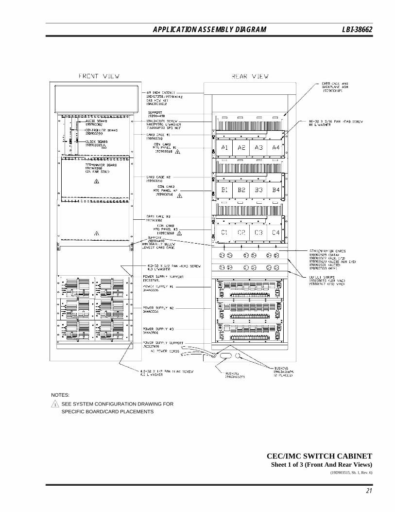
Most CEC/IMC switch components are housed ineither one or two 69-inch (69") high steel cabinets. Eachstandard 19-inch rack-mount cabinet can hold a maximumof three (3) Card Cage and Backplane Assemblies, three (3)Redundant Power Supply (RPS) units, up to twelve (12)Concentrator Cards, and the associated interconnectingcables.
The Card Cage and Backplane Assemblies, mountedon the front and middle vertical mounting rails, furnishhousing and electrical interconnections for all of theprimary printed circuit boards used in the network switch.Each assembly occupies six rack units (10.5 inches) andwill accept twenty-one (21) CEC/IMC boards. See theApplication Assembly Diagram in this manual for specifichardware requirements.
All Backplanes (except the CIA racks) areinterconnected or "daisy-chained" together using multi-conductor ribbon cable pairs referred to as "intra-rack" and"inter-rack" cables. Intra-rack cables join the Backplanes inan individual cabinet together and inter-rack cables join theBackplanes between cabinets in a dual-cabinet installation.
Generally, a dual-cabinet CEC/IMC network switchwill have an opening cut in adjacent sides of each cabinetfor passage of the inter-rack cables. This procedure allowsthe inter-rack cable lengths to be minimized.
Each CIA rack uses a single Card Cage and BackplaneAssembly with Terminator Boards installed on each end ofthe Backplane. This rack contains the CCI ControllerBoard and up to eight (8) CI Boards. Support for two (2)CIA racks is provided per CEC/IMC switch to give a totalof sixty-four (64) duplex conventional channel audio links.
There is an RPS unit for every Card Cage andBackplane Assembly (maximum of three per cabinet). TheRPS units are mounted in the lower cabinet positions; each
one occupies three rack units (5.25 inches). A power cableinterconnects the RPS unit to its respective Backplane. Seethe Application Assembly Diagram for interconnectiondetails.
Concentrator Cards simplify connections to theCEC/IMC switch by allowing many signals to be neatlyrouted between the switch and punch blocks. As shown inthe Application Assembly Diagram, the cards are labeledA1 - A4, B1 - B4 and C1 - C4. Each group of four ismounted on a hinged horizontal panel on the rear cabinetrails. These panels can be swung out to gain access to therear of the Backplanes and the Concentrator Cards duringservice and upgrade procedures. The hinge is located on theright rear-most mounting rail as viewed from the rear of thecabinet.
In addition, every cabinet has a top-mounted cabinetfan and ac outlet strips. The ac outlet strips are horizontallymounted between the middle rails.
GETC Uplink Cabinets
Every MIM Controller Board requires a GETC uplinkfor control data transfer between a MIM and an EDACSradio system. The co-located 69-inch GETC uplink cabinetswill each house up to nine (9) GETC main/standby pairs.
Operating dc power for all GETCs within the cabinet isprovided by a single 13-volt 30-amp power supply and two(2) fused power distribution panels. These units aremounted at the bottom of the cabinet. See the ApplicationAssembly Diagram for cabinet rack-up details.
DVIU Cabinets
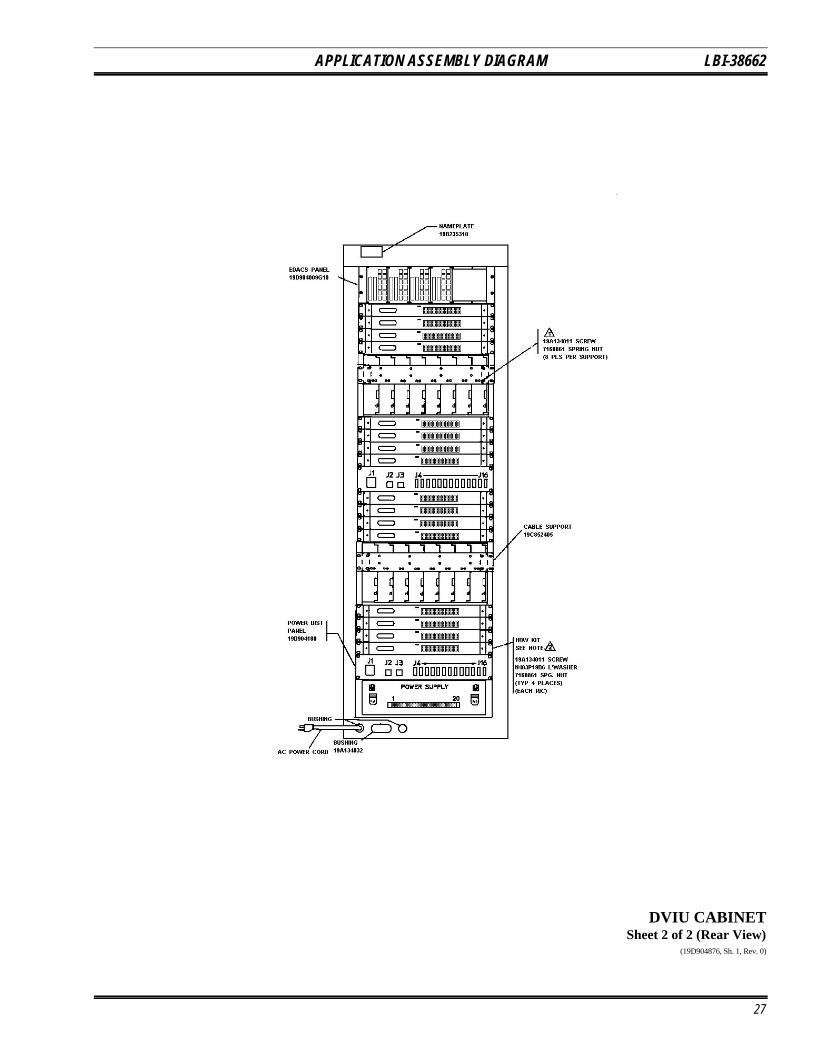
The co-located 69-inch DVIU cabinet can house up tosixteen (16) DVIUs. The DVIUs interface with a DVIM togive the CEC/IMC switch Aegis digital and Aegisencrypt/decrypt (private) capability. Each DVIU containsan Aegis module that performs these functions for dispatchconsole and CTIS support. See the Application AssemblyDiagram for cabinet rack-up details.
DISTRIBUTED ARCHITECTUREADVANTAGES
The CEC/IMC switch is designed with a distributedarchitecture scheme. Logical functions are shared by thevarious interface modules and each interface module sharesin the computational work-load of the switch. Eachinterface module is responsible only for its connecteddevice (site, console, etc.).
13
LBI-38662
When compared to a central architecture switch, adistributed architecture switch has several importantadvantages. They include:
• the ability to continue wide-area calls betweenother areas after failure of a single interfacemodule
• faster data transfer rates
• more flexible expansion and service capabilities
OPERATION DURING FAILUREOF AN INTERFACE MODULE
Distributed architectural design safeguards againstcatastrophic failures within the switch and between radiosystems. The CEC/IMC switch will not completely fail ifone or more interface modules fail. Wide-areacommunications can continue despite interface modulefailure. Only the devices (site, console, etc.) connected tothe failed interface module will be unable to participate inwide-area calls and other features provided by the switch.
Communications in the area served by the failedinterface module are not disabled. For example, failure of aMIM will not disable the EDACS radio system to which theMIM is connected. The radio system continues to operateand communications within the area covered by the radiosystem are unaffected by the respective MIM failure withinthe switch.
FASTER DATA TRANSFERS
A distributed architecture multisite switch has muchfaster data transfer rates than a comparable centralarchitecture multisite switch. Since central computersprocess data serially, all communications passing throughthe switch must be serially processed by the CPU; therefore,the CPU in a central architecture switch slowscommunications, especially during busy times. Adistributed architecture multisite switch utilizes parallelprocessing techniques through the shared computationaltasks of many processors. Generally, distributed switchesare significantly faster than comparable central switches.
EXPANSION AND SERVICE CAPABILITY
A distributed switch can be easily expanded by addingadditional interface modules. Expanding a central switchmay require purchasing a larger central computer.
Each CEC/IMC interface module is supported by aController Board and, in most cases, one or more AudioBoards. The MIM may also contain a secondary (standby)Controller Board for backup operation. Boards are easilyinterchangeable between different interface modules sincethey have the same hardware and software components.DIP switches on the Controller Boards are used toconfigure its interface module type. This interchangecapability reduces service time and the resulting multisitedown-time when a board failure occurs. The service shopno longer needs to stock a large variety of replacementboards and the service technician does not need to reviewmany different volumes of manuals on specific circuitry foreach interface module.
14

LBI-38662
GLOSSARYAegis Aegis is the Ericsson GE's voice scrambling system that employs advanced Digital Signal Processing
(DSP) circuitry. Aegis has two primary modes − "Aegis digital" and "Aegis private". Aegis digitalmode offers improved weak signal performance and impedance to unauthorized monitoring. Aegisdigital transmissions are not encrypted. Aegis private mode also offers improved weak signalperformance. In addition, since Aegis private transmissions are encrypted, Aegis private mode providesvery secure communications against unauthorized monitoring.
Audio Board The Audio Board routes audio, mobile data and Aegis data between EDACS radio systems, dispatchconsoles, logging recorders, etc. The board digitizes analog signals applied to its audio inputs andapplies the digitized signals to the TDM bus. It also performs the reverse process for its audio outputs.
C3 Maestro The C3 Maestro is the CRT-type console that is designed to take advantage of the advanced featuresof EDACS. It consists of a specialized audio "tower" and an IBM PC compatible computer runningcustom software developed by Ericsson GE.
CAM C entralized Activity Module − The CAM is a CEC/IMC interface module that provides call activityinformation to the Centralized Activity Logger (CAL ) computer. Usage and billing information can begenerated with the CAL through the CAM link.
CCI Board Conventional Control Interface Board − This is a CEC/IMC Controller Board configured for use inthe CIA rack. It provides master CI Board control. The control data port that connects the CIA rack tothe VMIM is also located on the CCI Board. (Also see CI Board.)
CEC Console Electronics Controller − The Ericsson GE CEC is an advanced radio communicationscontroller incorporating time division multiplex digital audio switching technology. The CEC connectsdispatch consoles to EDACS and CNI systems.
CEC/IMC Manager The CEC/IMC Manager (formerly referred to as the "MOM PC") provides CEC/IMC switchmonitoring and configuration functions. This IBM PC compatible computer running custom softwaredeveloped by Ericsson GE is the window into the CEC/IMC switch for the system administrator andservice technicians.
CIA rack C onventional Interface Adapter rack − The CIA rack allows conventional tone and dc controlled basestations and voting systems to be connected to the CEC/IMC switch. It is considered a "secondaryinterface" since it does not have direct TDM and GSC bus connections to the primary CEC/IMCinterface modules.
CI Board Conventional Interface Board − This board is located in the CIA secondary interface rack. It containscircuitry used to connect conventional tone and dc controlled base stations and voting systems to theCEC/IMC switch.
CIM C onsole Interface Module − The CIM is a CEC/IMC interface module used to connect C3 Maestro(CRT-type) and C3 Modular/Desktop consoles to the CEC/IMC switch. C3 Modular/Desktop consolesalso require a C3 Console Translator interface module. (Also see XLTR.)
CNI Conventional Network Interface − A conventional base station can be connected to the CEC/IMCswitch via a CNI. The CNI is formed by a GETC shelf located at the conventional station that makesthe station appear to a MIM as an EDACS site. In the CNI system, different Channel Guard tones areassigned to different talk groups.
confirmed call The confirmed call function ensures all EDACS radio systems being called have working channelsavailable before the caller is given a channel access (talk permit) tone. This function can be disabledon a per system/group basis.
control data Control data includes any data used by the switch for system control.
Controller Board The Controller Board processes control data, holds databases, and controls the Audio Boards withinits respective interface module.
CONV MIM (see VMIM )
15
LBI-38662
CTIM C entralized Telephone Interconnect Module − The CTIM is a CEC/IMC interface module used toconnect Centralized Telephone Interconnect System (CTIS) equipment to the switch so radio usersand dispatchers can access land-line telephone systems.
DATA (see EDG interface module)
distributed multisite Two or more IMC networks can be linked together for distributed multisite communication. Audio,mobile data/Aegis data and control data is transferred between the different IMC networks via a NIMat each IMC switch. (Also see StarGate Controller.)
DPRAM Dual Port Random Access Memory − These specialized memory chips have two separate data busesthat allow two microprocessor chips to quickly and efficiently transfer data between each other.
DVIM D igital Voice Interface Module − The DVIM is a CEC/IMC interface module that connects DigitalVoice Interface Units (DVIU ) to the switch to provide Aegis digital and Aegis private voice operationfor dispatch consoles and CTIS equipment.
EDACS radio system Enhanced Digital Access Communication System radio system − The term "EDACS radio system"refers to RF equipment that may be interfaced to the EDACS CEC/IMC switch. The RF equipmentmay be located at a single location, such as an EDACS site or it may be located at several locations,such as in a voting system. Other examples of EDACS radio systems include simulcast, CNI, andSCAT systems.
EDG interface module EDACS Data Gateway interface module − Mobile data is forwarded to the CEC/IMC switch fromthe EDG computer equipment via the EDG interface module. This module's Controller Board islabeled "DATA ".
GETC Ericsson General Electric Trunking Card − The GETC is a microprocessor-controlled shelf that can beconfigured to perform many different signal processing tasks for Ericsson GE radio communicationsequipment. In CEC/IMC applications, each GETC is equipped with a 9600 baud modem that providesserial control data communications between different radio systems.
GSC bus Global Serial Channel bus − The GSC bus is a high-speed serial bus that provides packetized controldata transfers between Controller Boards in the CEC/IMC switch.
IMC I ntegrated Multisite and Console Controller − The Ericsson GE IMC is a digital audio switch thatroutes audio/mobile data/Aegis data between EDACS radio systems and dispatch consoles. It is asecond generation multisite controller plus a console controller for the C3 series consoles.
interface module The term "CEC/IMC interface module" is used to refer to a subset of hardware components within theCEC/IMC switch that permits it to be connected or linked to an external device such as a dispatchconsole or an EDACS radio system. Each interface module is formed by a Controller Board and usuallyone or more Audio Boards. This term replaces the term "subsystem". Examples of CEC/IMC interfacemodules include: MIM, CIM, LRIM, VMIM and RIM.
inter- & intra-rack cables The CEC/IMC Backplanes are interconnected or "daisy chained" together using inter-rack and intra-rack cables. Intra-rack cables join the Backplanes in an individual cabinet together and inter-rackcables join the Backplanes between cabinets in a dual-cabinet installation.
LRIM L ogging Recorder Interface Module − This CEC/IMC interface module provides audio outputs forlogging recorders. Each output channel can be programmed to supply audio based on groups orindividual units within the CEC/IMC network.
MIM M ASTR II/III Interface Module − The MIM connects an EDACS radio system to the CEC/IMCswitch. EDACS radio systems include EDACS sites, simulcast systems, voted systems, CNI and SCATsystems.
mobile data/Aegis data This includes mobile data, Aegis digitized voice data and Aegis encrypted voice data.
MOM MO nitor Module − The MOM is a CEC/IMC interface module that provides serial data connectionsfor the CEC/IMC Manager (MOM PC) and the System Manager computers.
MOM PC (see CEC/IMC Manager )
multisite A multisite is a network of multiple EDACS radio systems and possibly conventional radio systems alllinked together for wide-area communication. In a multisite network, adjacent systems do not use thesame radio frequencies.
16

LBI-38662
NIM N etwork Interface Module − Two or more IMC networks can be linked together for distributedmultisite communications using a NIM at each IMC switch.
patch A patch is when two or more talk groups are connected together by a dispatcher. This allows thepatched groups to communicate as a single group.
PCM Pulse Code Modulation − An audio processing technique used to encode and decode analog signals sothey can be transferred digitally.
RIM R equest Status Monitor Interface Module − The RIM interface module enables the RSM computer torequest status information from radios within the network.
RSM Request Status Monitor − The RSM is an IBM PC compatible computer running custom softwaredeveloped by Ericsson GE. It allows the system administrator and/or the dispatchers to view status ofEDACS units within the CEC/IMC network. Status information is typically initiated (transmitted) bythe radio operator to identify the current condition (in route, at scene, etc.) of the unit.
secondary interface The term "secondary interface" refers to the CIA rack. This rack is considered to be secondarybecause it is not connected to the primary TDM and GSC buses within the CEC/IMC.
simul-select A console operator can simultaneously communicate with two or more talk groups by selecting thegroups for "simul-select" communication. Simul-select communication uses only a single radiochannel at each active radio system.
site This term normally refers to EDACS radio equipment at a single specific location.
StarGate Controller A StarGate Controller is an IMC switch specifically configured for distributed multisite operation. Itis the central point or "hub" for all distributed multisite communications.
System Manager The System Manager is a DEC multitasking computer which performs features such as monitoringsystem operation, generating management reports, individual unit enable/disable and dynamicregrouping.
TDM bus T ime Division Multiplexed bus − The TDM bus in the CEC/IMC switch is a digitally multiplexed bussystem used to transfer audio/mobile data/Aegis data throughout the CEC/IMC switch. Each signalcoming into the CEC/IMC switch is assigned a TDM time slot and receiving devices extract thedigitized signals from the appropriate time slot.
tracking In a multisite network, all active radios log into their particular system. This login information isdatabased to allow the CEC/IMC to track individual radio units as they move from system-to-system.The CEC/IMC can then route wide area calls based on this database.
VMIM ConVentional Interface Module − The VMIM couples the CIA secondary interface rack to the primaryCEC/IMC switch interface modules. The VMIM - CIA set allows conventional base stations andconventional satellite receiver voting systems to be connected to the CEC/IMC switch.
XLTR C3 Modular/Desktop Console Translator − Using data protocol conversion techniques, this interfacemodule allows the CEC/IMC switch to communicate with a C3 Modular/Desktop console. The XLTRis placed in the control data path between the C3 console and its respective CIM.
Ericsson GE Mobile Communications Inc.Mountain View Road • Lynchburg Virginia 24502
17

LBI-38662
Figure 2A - CEC/IMC Architecture
18

LBI-38662
Figure 2B - CEC/IMC Architecture
19
LBI-38662
Figure 3 - Interface Module Architecture
Figure 4 - Controller Board Architecture
20
APPLICATION ASSEMBLY DIAGRAM LBI-38662
SEE SYSTEM CONFIGURATION DRAWING FOR
SPECIFIC BOARD/CARD PLACEMENTS1
NOTES:
CEC/IMC SWITCH CABINETSheet 1 of 3 (Front And Rear Views)
(19D903515, Sh. 1, Rev. 6)
21
LBI-38662 APPLICATION ASSEMBLY DIAGRAM
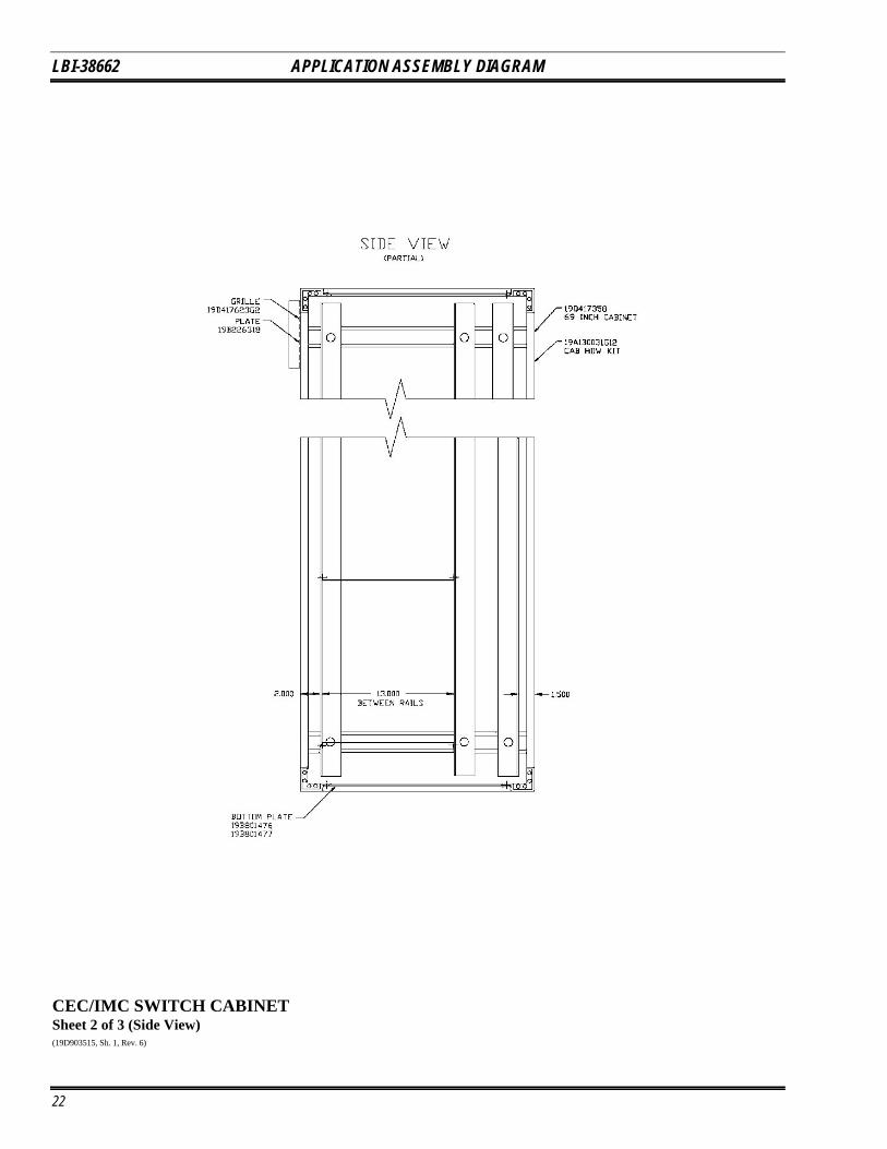
CEC/IMC SWITCH CABINETSheet 2 of 3 (Side View)(19D903515, Sh. 1, Rev. 6)
22

APPLICATION ASSEMBLY DIAGRAM LBI-38662
CEC/IMC SWITCH CABINETSheet 3 of 3 (Backplane Connections)
(19D903515, Sh. 2, Rev. 4)
23

LBI-38662 APPLICATION ASSEMBLY DIAGRAM
GETC UPLINK CABINETSheet 1 of 2 (Front View)(19D903515, Sh. 4, Rev. 4
24

APPLICATION ASSEMBLY DIAGRAM LBI-38662
GETC UPLINK CABINETSheet 2 of 2 (Rear Views)
(19D903515, Sh. 4, Rev. 4)
25

LBI-38662 APPLICATION ASSEMBLY DIAGRAM
DVIU CABINETSheet 1 of 2 (Front View)(19D904876, Sh. 1, Rev. 0)
26
APPLICATION ASSEMBLY DIAGRAM LBI-38662
DVIU CABINETSheet 2 of 2 (Rear View)
(19D904876, Sh. 1, Rev. 0)
27

LBI-38662 CABLE ASSEMBLY DIAGRAM
LOCAL BUS CABLES344A3728P1 (3.25") & P2 (8.00")(344A3728, Sh. 1, Rev. 2)
28

CABLE ASSEMBLY DIAGRAM LBI-38662
INTRA- & INTER-RACK CABLES19B235983P3 - P7
(19B235983, Sh. 1, Rev. 3)(19B235983, Sh. 2, Rev. 3)
29
LBI-38662 CABLE ASSEMBLY DIAGRAM
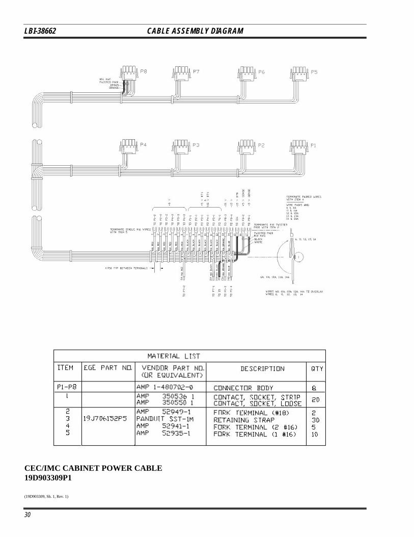
CEC/IMC CABINET POWER CABLE19D903309P1
(19D903309, Sh. 1, Rev. 1)
30

CABLE ASSEMBLY DIAGRAM LBI-38662
CEC/IMC CONCENTRATOR CARD CABLES19D903628 (Figures 1 & 2)
(19D903628, Sh. 1, Rev. 4)
31
LBI-38662 CABLE ASSEMBLY DIAGRAM
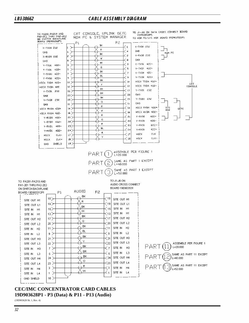
CEC/IMC CONCENTRATOR CARD CABLES19D903628P1 - P3 (Data) & P11 - P13 (Audio)(19D903628 Sh. 1, Rev. 4)
32

CABLE ASSEMBLY DIAGRAM LBI-38662
CEC/IMC CONCENTRATOR CARD CABLES19D903628P21 - P29 (Translator) & P31 - P33 (VMIM)
(19D903628 Sh. 1, Rev 4)
33
LBI-38662 CABLE ASSEMBLY DIAGRAM
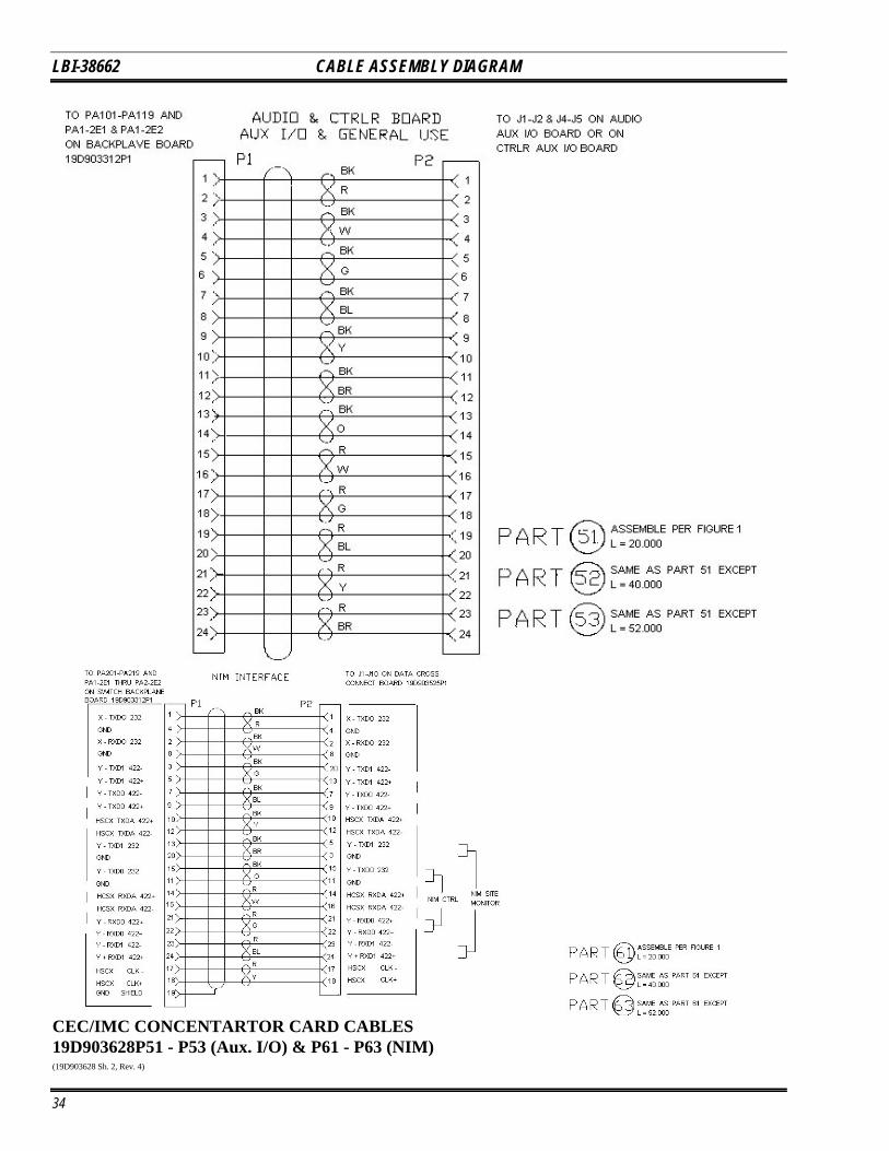
CEC/IMC CONCENTARTOR CARD CABLES19D903628P51 - P53 (Aux. I/O) & P61 - P63 (NIM)(19D903628 Sh. 2, Rev. 4)
34
CABLE ASSEMBLY DIAGRAM LBI-38662
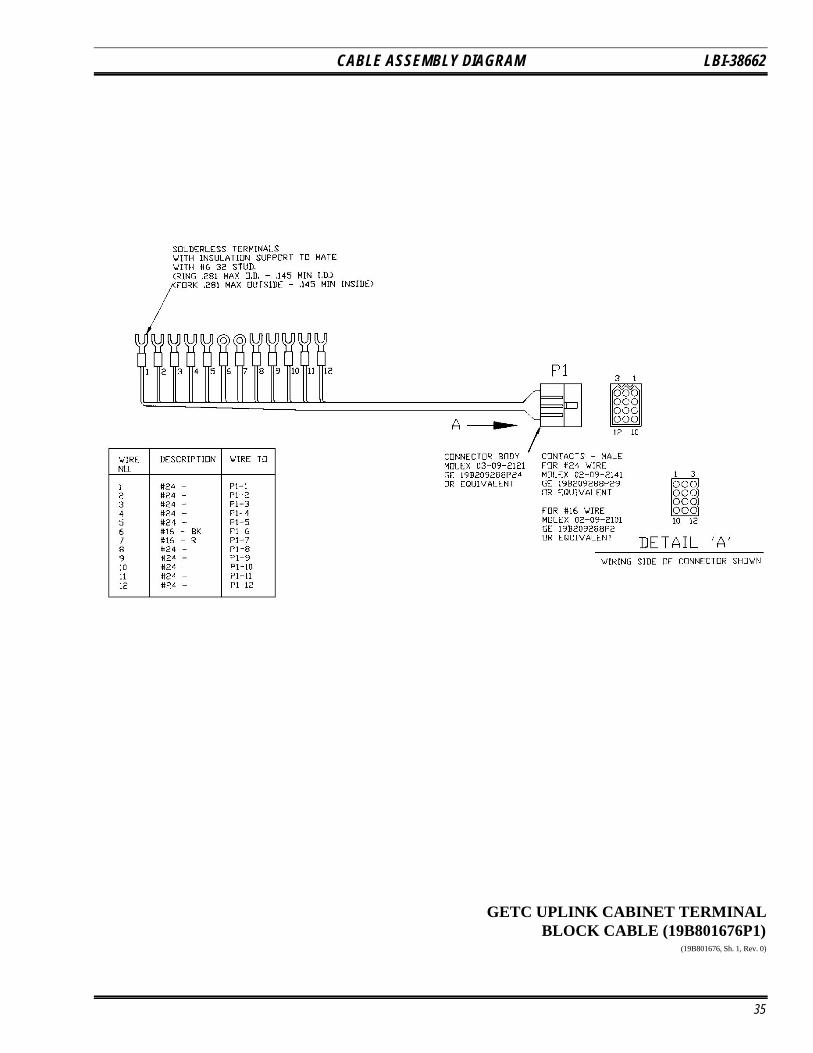
GETC UPLINK CABINET TERMINALBLOCK CABLE (19B801676P1)
(19B801676, Sh. 1, Rev. 0)
35

LBI-38662 CABLE ASSEMBLY DIAGRAM
GETC UPLINK CABINET POWER/PHONELINE CABLE 19D902759P1(19D902759, Sh. 1, Rev. 1)
36

CABLE ASSEMBLY DIAGRAM LBI-38662
GETC UPLINK CABINET POWER/PHONELINE CABLE 19D902759P1
(19D902759, Sh. 1, Rev. 1)
37
LBI-38662 CABLE ASSEMBLY DIAGRAM
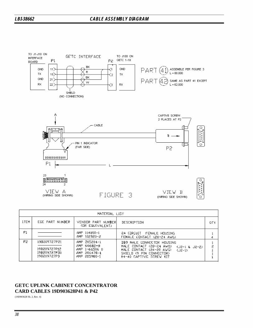
GETC UPLINK CABINET CONCENTRATORCARD CABLES 19D903628P41 & P42(19D903628 Sh. 2, Rev. 4)
38