LBB SERIES OVEN OWNER’S MANUAL - despatch.com Series Owners Manual-C188 V18… · This owner’s...
74
LBB Series Oven Owner’s Manual PREFACE Version 18 1 LBB SERIES OVEN OWNER’S MANUAL C-188 PN 336979 VERSION 18 6/2014
Transcript of LBB SERIES OVEN OWNER’S MANUAL - despatch.com Series Owners Manual-C188 V18… · This owner’s...

LBB Series Oven Owner’s Manual PREFACE
Version 18 1
LBB SERIES OVEN
OWNER’S MANUAL
C-188
PN 336979
VERSION 18
6/2014
LBB SERIES OVEN
OWNER’S MANUAL
C-188
PN 336979
VERSION 18
6/2014
PREFACE LBB Series Oven Owner’s Manual
2 Version 18
Revision History Revision Date Author Description
C Updated electrical drawings in DRAWINGS AND SPARE PARTS LISTS section.
D Corrections.
E Correction, page 19, set-up parameter table
F Parts lists corrections in DRAWINGS AND SPARE PARTS LISTS section
G Corrections to SPECIFICATIONS section, addition of options and features in APPENDIX
H Change Product Warranty page
I Update drawings and High Limit information
J Parts lists corrections in DRAWING AND SPARE PARTS LISTS section. Corrected Despatch address.
K Parts lists corrections in DRAWING AND SPARE PARTS LISTS section
L Updated warranty
12 3/2011 Livingston Revise format
13 9/2011 Livingston Additional parts tables
14 6/2012 Livingston Update for Protocol 3
15 8/2012 Livingston Corrections—Power Section.
15 7/2013 Livingston Corrections—Minor correction to header.
16 8/2013 Meyer Correction to LBB2-12 spare parts list
17 2/2014 Livingston Minor copy changes. Remove LBB1-43 references.
17.1 4/2014 Livingston Revised schematics added plus various small changes.
18 5/2014 E. Anderson R3 REV -2 modifications
LBB Series Oven Owner’s Manual PREFACE
Version 18 3
PREFACE LBB Series Oven Owner’s Manual
4 Version 18

LBB Series Oven Owner’s Manual PREFACE
Version 18 5
Table of Contents 1. About This Manual ............................................................................................................. 8
1.1. Important User Information ..................................................................................... 8 1.2. Manufacturer & Service .......................................................................................... 9 1.3. Organization of this Manual .................................................................................... 9 1.4. Conventions ........................................................................................................... 10 1.5. Specifications ........................................................................................................ 11 1.5.1. Dimensions ........................................................................................................ 11 1.5.2. Capacities .......................................................................................................... 12 1.5.3. Power ................................................................................................................. 13 1.5.4. Temperature ....................................................................................................... 14 1.5.5. LBB Series Oven Operating Conditions ........................................................... 14
2. Safety ................................................................................................................................ 15 2.1. Safety Information ................................................................................................. 15 2.1.1. Lockout .............................................................................................................. 15 2.1.1.1. Lockout Requirements ................................................................................... 15 2.1.1.2. Lockout Procedure ......................................................................................... 15 2.2. Provisions for Lifting and Carrying....................................................................... 16 2.3. Maintenance .......................................................................................................... 16 2.4. Electrical Power ..................................................................................................... 16 2.5. Fire ......................................................................................................................... 17 2.6. Equipment Lockout Requirements ........................................................................ 17 2.6.1. Emergency Stop ................................................................................................. 18 2.7. Disconnecting Devices .......................................................................................... 18 2.7.1. Power Requirements .......................................................................................... 18 2.7.2. Disconnecting Hard-Wired Units ...................................................................... 18 2.7.3. Disconnecting Corded Units .............................................................................. 19 2.7.4. Disconnecting Units with (Optional) Disconnect Switch .................................. 19
3. Theory of Operation ......................................................................................................... 20 3.1. The LBB Series Oven ............................................................................................ 20 3.1.1. Oven Theory ...................................................................................................... 21 3.2. Control Systems..................................................................................................... 21 3.2.1. Primary Control Instrument ............................................................................... 21 3.2.2. High Limit Instrument ....................................................................................... 22 3.2.2.1. Product High Limit Instrument ...................................................................... 23 3.2.2.2. Oven High Limit Instrument ......................................................................... 23 3.3. The Protocol 3 Controller (Optional) .................................................................... 23
4. Assembly & Setup ............................................................................................................ 24 4.1. Unpack & Inspect the LBB Series Oven ............................................................... 24 4.1.1. If Damaged During Shipping ............................................................................ 24 4.2. Set-up the LBB Series Oven .................................................................................. 24 4.2.1. Select Oven Location/Operating Environment .................................................. 24 4.2.2. Set-up Procedure ............................................................................................... 25 4.2.3. Wiring & Power Connections ........................................................................... 25
5. Operation .......................................................................................................................... 28 5.1. Load Oven ............................................................................................................. 28 5.2. Pre-Startup Checklist ............................................................................................. 29 5.3. Operating Procedure—Standard Control Instrument ............................................ 30 5.3.1. Start Oven .......................................................................................................... 30 5.4. Working with the Control Instrument ................................................................... 32

PREFACE LBB Series Oven Owner’s Manual
6 Version 18
5.4.1. Change Setpoint................................................................................................. 32 5.4.2. Control Instrument Parameter Programming Mode .......................................... 33 5.4.2.1. Entering Control Instrument Set-up and Configuration Mode ...................... 33 5.4.2.2. Control Instrument Operating Mode Notes ................................................... 34 5.4.3. Change Control Instrument Display from Centigrade to Fahrenheit ................. 35 5.4.4. Oven Zone Calibration ...................................................................................... 36 5.4.5. Set the High Limit ............................................................................................. 37 5.4.5.1. Change the High Limit Instrument Setpoint .................................................. 37 5.4.6. High Limit Instrument Parameter Setup Mode ................................................. 37 5.4.7. High Limit Instrument Setup Parameters .......................................................... 38 5.4.8. Change High Limit instrument Display from Centigrade to Fahrenheit .......... 39 5.5. Working with Optional Protocol 3 Controller Operating Modes .......................... 39
6. Maintenance ..................................................................................................................... 40 6.1. Checklist ................................................................................................................ 40 6.2. Lubrication ............................................................................................................ 41 6.3. Cleaning and Decontamination ............................................................................. 41 6.3.1. Cleaning the LBB Series Oven .......................................................................... 41 6.3.2. Decontaminating the LBB Series Oven ............................................................. 42 6.4. Routine Tests ......................................................................................................... 42 6.4.1. Test Control Instrument ..................................................................................... 43 6.4.2. Test High Limit Instrument ............................................................................... 43 6.5. Replacement Parts ................................................................................................. 43 6.5.1. Replace the Control Instrument ......................................................................... 44 6.5.2. Replace High Limit Instrument ......................................................................... 47 6.5.3. Replace (Optional) Protocol 3 Controller .......................................................... 49 6.5.4. Replace Heater Unit .......................................................................................... 49 6.5.5. Replace Fan Motor ............................................................................................ 51
7. Troubleshooting................................................................................................................ 54 Table 7. Common Technical Issues and Remedies. ...................................................................... 54
7.1. DES2000 Control Parameters Check .................................................................... 55 7.2. Hi Limit L91 Hi-Limit Reset ................................................................................. 57
8. Appendices ....................................................................................................................... 58 8.1. Standard Products Warranty .................................................................................. 58 8.2. Optional Equipment ............................................................................................... 59 8.2.1. Assemble Oven Stand ........................................................................................ 59 8.2.2. End of Cycle (EOC) Timer Option.................................................................... 60 8.2.3. Operating the Timer .......................................................................................... 61 8.2.4. Parameter Default Settings ................................................................................ 63 8.2.5. Timer Option with Audible and Visual Alarm .................................................. 63 8.2.6. High Alarm Limit Option .................................................................................. 63 8.3. Part Lists ................................................................................................................ 64 8.4. Mechanical Drawing ............................................................................................. 64 8.5. Electrical Schematics ............................................................................................. 64
LBB Series Oven Owner’s Manual PREFACE
Version 18 7
Figures Figure 1. Disconnect Switch.......................................................................................................... 19 Figure 2. LBB Forced Convection Benchtop Oven. ..................................................................... 20 Figure 3. Uniflow Airflow through the LBB Oven. ...................................................................... 20 Figure 4. LBB Series Oven Primary Control Instrument .............................................................. 21 Figure 5. High Limit Instrument. .................................................................................................. 22 Figure 6. Protocol 3 Operator Interface. ........................................................................................ 23 Figure 7. LBB Series Oven Name Plate Example. ........................................................................ 26 Figure 8. LBB Series Oven with Top Removed. ........................................................................... 26 Figure 9. Wiring Access through Rear of Oven. ........................................................................... 27 Figure 10. Close-up of Connector Block. ...................................................................................... 27 Figure 11. LBB Series Oven Control Panel. ................................................................................. 31 Figure 12. Adjust Damper to Set Exhaust Vent by rotating the outer component. ....................... 31 Figure 13. Remove Control Panel to Access Control Instrument (using T20 Torx bit driver). .... 44 Figure 14. Providing easy access to the Control instrument. ........................................................ 45 Figure 15. Remove old Control and High Limit Instruments and Wiring (Rear View). ............... 45 Figure 16. Prepare to remove control instrument by removing the mounting bracket. ................. 46 Figure 17. Connections to Control Instrument. ............................................................................. 46 Figure 18. High Limit Connector Block on Control Board. .......................................................... 47 Figure 19. Press and Hold Tabs to Remove High Limit Instrument. ............................................ 48 Figure 20. Connections to High Limit Instrument. ....................................................................... 48 Figure 21. Remove Screws to Remove Each Duct (using T15 Torx bit driver. ............................ 49 Figure 22. Heater element connections. ........................................................................................ 50 Figure 23. Typical Heating Element (Inset connections see Figure 22) . ...................................... 51 Figure 24. Fan Motor Location. .................................................................................................... 52 Figure 25. Separate fan wheel from fan motor shaft. .................................................................... 53 Figure 26. Optional LBB Oven Stand. .......................................................................................... 59 Figure 27. Timer Option Displays and Switches. .......................................................................... 60 Figure 28. LBB1-23 Mechanical Drawing .................................................................................... 65 Figure 29. LBB1-69 Mechanical Drawing .................................................................................... 66 Figure 30. LBB2-12 Mechanical Drawing .................................................................................... 67 Figure 31. LBB2-18 Mechanical Drawing .................................................................................... 68 Figure 32. LBB2-27 Mechanical Drawing .................................................................................... 69 Figure 33. LBB Standard (120 V) Schematic................................................................................ 70 Figure 34. LBB Standard (240 V) Schematic................................................................................ 70 Figure 35. LBB Opt P-3 (120 V) Schematic. ................................................................................ 70 Figure 36. LBB Opt P-3 (240 V) Schematic. ................................................................................ 70
Tables Table 1. Operating/Environmental Conditions (For indoor use). .................................................. 14 Table 2. Control Instrument Explanations. .................................................................................... 22 Table 3. High Limit Instrument Explanations. .............................................................................. 22 Table 4. Control Instrument Set-up Parameters. ........................................................................... 33 Table 5. Control Instrument Configuration Parameters. ............................................................... 34 Table 6. High Limit instrument Setup Parameters. ....................................................................... 38 Table 7. Common Technical Issues and Remedies. ...................................................................... 54
ABOUT THIS MANUAL LBB Series Oven Owner’s Manual
8 Version 18
1. About This Manual
1.1. Important User Information
Copyright © 2014 by Despatch Industries.
All rights reserved. No part of the contents of this manual may be reproduced, copied, or
transmitted in any form or by any means including graphic, electronic, or mechanical methods or
photocopying, recording, or information storage and retrieval systems without the written
permission of the publisher, unless it is for the purchaser's personal use.
Produced in the United States of America.
The information in this manual is subject to change without notice and does not represent a
commitment on the part of Despatch Industries. Despatch Industries does not assume any
responsibility for any errors that may appear in this manual.
In no event will Despatch Industries be liable for technical or editorial omissions made herein,
nor for direct, indirect, special, incidental, or consequential damages resulting from the use or
defect of this manual.
Values displayed on screens are examples only. Though those values may be typical, contact Despatch Industries for the final value.
Users of this equipment must comply with operating procedures and training of operation personnel as required by the Occupational Safety and Health Act (OSHA) of 1970, Section 5 and relevant safety standards, as well as other safety rules and regulations of state and local governments. Refer to the relevant safety standards in OSHA and National Fire Protection Association (NFPA), section 86 of 1990.

LBB Series Oven Owner’s Manual ABOUT THIS MANUAL
Version 18 9
Danger! Only fully-trained and qualified personnel should setup and maintain this equipment. Improper setup and operation of this equipment could cause an explosion that may result in equipment damage, personal injury or possible death.
The information in this document is not intended to cover all possible conditions and situations
that might occur. The end user must exercise caution and common sense when installing or
maintaining Despatch Industries products. If any questions or problems arise, call Despatch
Industries at 1-800-762-0110 or 1-952-469-5424.
1.2. Manufacturer & Service The LBB Series oven is manufactured by Despatch Industries.
Despatch has specialized in thermal processing for over 100 years. Technical expertise gained
over those years helps provide innovative solutions to critical applications in vertical markets and
cutting edge technology worldwide. Despatch products are backed by a drive for long-term
customer satisfaction and a strong sense of responsibility. The worldwide network of factory-
trained Service Professionals is available to support your Despatch equipment. From full service
preventive maintenance to routine repair and certified calibration and uniformity, the Despatch
service network is positioned to respond to your business needs. Our service programs are
customized to meet your specific needs using our Advantage Service Assurance Program
(ASAP). For more information on ASAP, visit www.despatch.com.
Global Headquarters Contact Service & Technical
Support
Despatch Industries 8860 207th Street Lakeville, MN 55044 USA
International/Main: 1-952-469-5424 US toll free: 1-800-726-0110 Fax: 1-952-469-4513 [email protected] www.despatch.com
Service: 1-952-469-8230 US toll free: 1-800-473-7373 Service @despatch.com
1.3. Organization of this Manual This owner’s manual contains the most comprehensive set of information for the Despatch LBB
Series ovens, including installation instructions, theory of operation, and operating instructions,
among other things.
ABOUT THIS MANUAL LBB Series Oven Owner’s Manual
10 Version 18
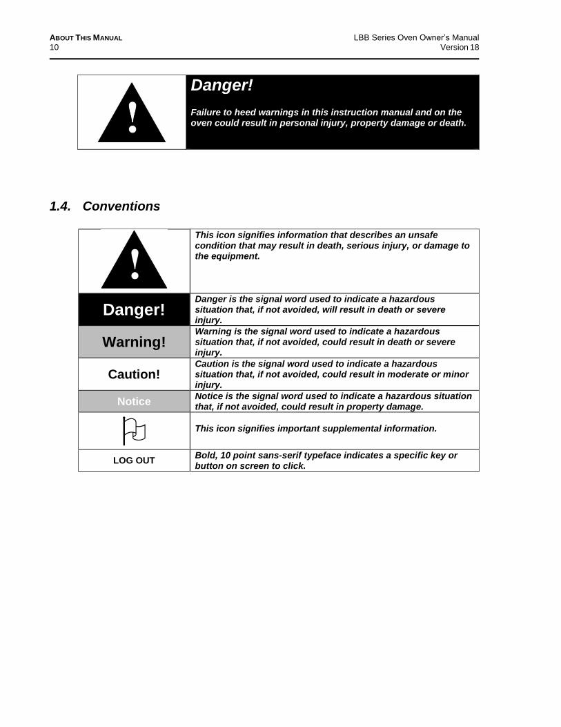
Danger! Failure to heed warnings in this instruction manual and on the oven could result in personal injury, property damage or death.
1.4. Conventions
This icon signifies information that describes an unsafe condition that may result in death, serious injury, or damage to the equipment.
Danger! Danger is the signal word used to indicate a hazardous situation that, if not avoided, will result in death or severe injury.
Warning! Warning is the signal word used to indicate a hazardous situation that, if not avoided, could result in death or severe injury.
Caution! Caution is the signal word used to indicate a hazardous situation that, if not avoided, could result in moderate or minor injury.
Notice Notice is the signal word used to indicate a hazardous situation that, if not avoided, could result in property damage.
This icon signifies important supplemental information.
LOG OUT Bold, 10 point sans-serif typeface indicates a specific key or button on screen to click.

LBB Series Oven Owner’s Manual ABOUT THIS MANUAL
Version 18 11
1.5. Specifications
1.5.1. Dimensions
LBB Model
No.
Chamber Size in (cm)
Capacity feet
3
(liters)
Overall Size in (cm)
Shelves Provided on Shelf Centers in (cm)
Maximum Number of
Shelf Positions
Chamber Doors
W0 D H W D H
1-23 18 (46)
18 (46)
12 (30)
2.3 (65)
24 (61)
23 (58)
26 (66)
2 on 2” (5.1)
5 1
1-69 30 (76)
18 (46)
22 (56)
6.9 (195)
34 (86)
23 (58)
36 (91)
2 on 2” (5.1)
10 2
2-12 30 (76)
20 (51)
35 (89)
12.1 (343)
36 (91)
25 (64)
51 (130)
2 on 2” (5.1)
16 2
2-18 37 (94)
24 (61)
35 (89)
18 (510)
43 (102)
29 (74)
51 (130)
2 on 2” (5.1)
16 2
2-27 37 (94)
37 (94)
35 (89)
27.7 (785)
43 (102)
42 (107)
51 (130)
2 on 2” (5.1)
16 2
The LBB oven is not intended to process solvents or other volatile or flammable materials. Oven exhaust is intended for cooling purposes only.
Warning! Do not place this oven in an environment harmful to electrical components. Placing this oven in an environment detrimental to electrical components (for example, environments where carbon fibers, coal dust or similar contaminants may be present) may result in component failure. Do not use liquids in the oven. Do not set product or liquids on top of the oven. Liquids that may spill on the oven floor or top of oven may cause considerable damage to the oven. Contact Despatch for options available to help prevent such failures.

ABOUT THIS MANUAL LBB Series Oven Owner’s Manual
12 Version 18
1.5.2. Capacities
Capacity
LBB Model Number
1-23 1-69 2-12 2-18 2-27
Maximum Load Lbs (Kg)
200 (91)
400 (181)
600 (272)
600 (272)
600 (272)
Maximum Shelf Load Lbs (Kgs)
50 (23)
200* (91)
200* (91)
200* (91)
200* (91)
Exhaust Capacity CFM (LPS)
1 (0.5)
3 (1.4)
12 (5.7)
14 (6.6)
14 (6.6)
*LBB1-69 and larger models have reinforced shelves.
Maximum load capacity not valid on ovens with the “control panel located on bottom” option.
Warning! Do not exceed a total of 400 Lbs. (181 Kg) for stacked LBB1-69 ovens.

LBB Series Oven Owner’s Manual ABOUT THIS MANUAL
Version 18 13
1.5.3. Power
If the line voltage for your LBB Series oven varies more than 10% from the oven voltage rating,
electrical components such as relays and temperature controls may operate erratically.
If the line voltage is lower than the oven voltage rating, heat-up time may be significantly
longer and motors may overload or run hot.
If the line voltage is higher than the nameplate rating, motors may run hot and draw excessive
amperage.
Model Volts Amps Hertz Phase Heater
KW Cord and Plug
LBB 1-23 120 11.6 50/60 1 1.2 Included, 15 Amp
LBB 1-23 240 5.8 50/60 1 1.2 Included, 15 Amp
LBB 1-69* 120 21.6 50/60 1 2.4 None, Hardwired
LBB 1-69* 240 10.8 50/60 1 2.4 None, Hardwired
LBB 2-12* 240 16.6 50/60 1 3.6 None, Hardwired
LBB 2-18* 240 16.7 50/60 1 3.6 None, Hardwired
LBB2-27* 240 21.7 50/60 1 4.8 None, Hardwired
* Models LBB1-69, LBB2-12, -18 and -27 must be hardwired to the electric supply using 10 AWG or
larger wire suitable for at least 75 °C (167 °F).
Ovens designed for 240 volts (check your oven nameplate for power requirement) will operate satisfactorily on a minimum of 208 volts, but with a 25% reduction in heater power. If your power characteristics are lower, contact Despatch industries.

ABOUT THIS MANUAL LBB Series Oven Owner’s Manual
14 Version 18
1.5.4. Temperature
Temperature and Parameters LBB Model Number
1-23 1-69 2-12 2-18 2-27
Time to temperature (approximate minutes with no load)
40°C-150°C
17 15 15 17 17
40°C-204°C
30 26 30 33 33
Recovery time with door open 1 minute (approximate minutes with no load)
150°C 2 3 3 3 4
204°C 4 6 6 7 8
Temperature uniformity at:
150°C +/- 3°C +/- 3°C +/- 2°C +/- 3°C +/- 3°C
204°C +/- 4°C +/- 4°C +/- 3°C +/- 4°C +/- 4°C
Operating range with 20°C ambient:
35°C- 204°C 40°C-204°C
Control stability ± 0.5 °C
Dampers must be open to operate at the minimum temperature.
“Time to Temperature” and “Temperature Uniformity” values are based on 240V/60 Hz operation, with control panel located on top. Actual results may vary slightly depending on unit configuration and operating conditions.
1.5.5. LBB Series Oven Operating Conditions
The LBB Series oven is for indoor use. Table 1 provides the operating conditions.
Table 1. Operating/Environmental Conditions (For indoor use).
Item Description
Operating Temperature* 18°C to 40°C (64.4°F to 104°F)
Relative Humidity 70% non‐condensing
Maximum Altitude 2,000 meters (6,600 feet)
* Fluctuations in temperature can occur at elevated ambient temperature values.

LBB Series Oven Owner’s Manual SAFETY
Version 18 15
2. Safety
2.1. Safety Information Do not work on the LBB Series oven without reading and understanding this section, which
contains important information and warnings. Ignoring these warnings can result in death, serious
injury or damage to the machine and product.
2.1.1. Lockout
Carefully follow the established Lock Out Tag Out policies of your company in all cases.
Machine lockout places the LBB Series oven into a zero energy state and prevents accidental
machine start up. Always follow the Lockout Procedure described in this section before cleaning,
maintaining or repairing the LBB Series oven. An accidental start-up, while working on the LBB
Series oven, can result in serious injury or death.
2.1.1.1. Lockout Requirements
1. Every power source that can energize any element of the LBB Series oven must be shut off at
the closest possible power source. This includes air, water and electricity, including the
Disconnect Switch.
2. After energy sources are locked out, test to ensure circuits are de-energized.
2.1.1.2. Lockout Procedure
Personnel authorized to lock out equipment must have the necessary locks to perform the lockout.
1. Physically disconnect all electrical power to the machine or lock out the appropriate breaker
or disconnects.
2. Close all valves and bleed off any pressure.
3. Test for power by attempting a start with the machine controls.
4. Identify the Lockout Condition with a tag on the electrical disconnect and pneumatic shut off
valve.
5. When work is complete, remove all tags and restore the machine to its working state.
Danger! Electrical panels contain high voltage. Disconnect and lock out the power supply before working inside any electrical panels. Failure to lock out the power supply can result in death or injury.

SAFETY LBB Series Oven Owner’s Manual
16 Version 18
2.2. Provisions for Lifting and Carrying
Caution! Do not tilt oven while lifting. Do not lift oven using the door handle to prevent damage to the oven and/or personnel involved.
Caution! Do not risk injury when lifting equipment. Take proper precautions when lifting, carrying or otherwise maintaining heavy items.
Notice How to lift the different sizes of ovens:
LBB1-23: Four people lift oven’s lower corners and place
on wheeled transport pallet. Push pallet to desired site
and lift oven from pallet, again lift using lower corners.
LBB1-69, LBB2-12, LBB2-18, LBB2-27: Do not lift by
hand. Lift with fork lifter and transport pallet.
2.3. Maintenance Only qualified and trained personnel should perform maintenance or repair.
2.4. Electrical Power Only qualified and trained personnel should perform electrical maintenance or electrical repair.
Danger! Contact with energized electrical sources may result in serious injury or death.
LBB Series Oven Owner’s Manual SAFETY
Version 18 17
Before performing maintenance, disconnect all electrical power from the machine. Use a
padlock and lock out all disconnects feeding power to the machine.
Never clean or repair the oven when in operation.
Unauthorized alterations or modifications to LBB Series oven are strictly forbidden. Never
modify any electrical circuits. Unauthorized modifications can impair the function and safety
of the LBB Series oven.
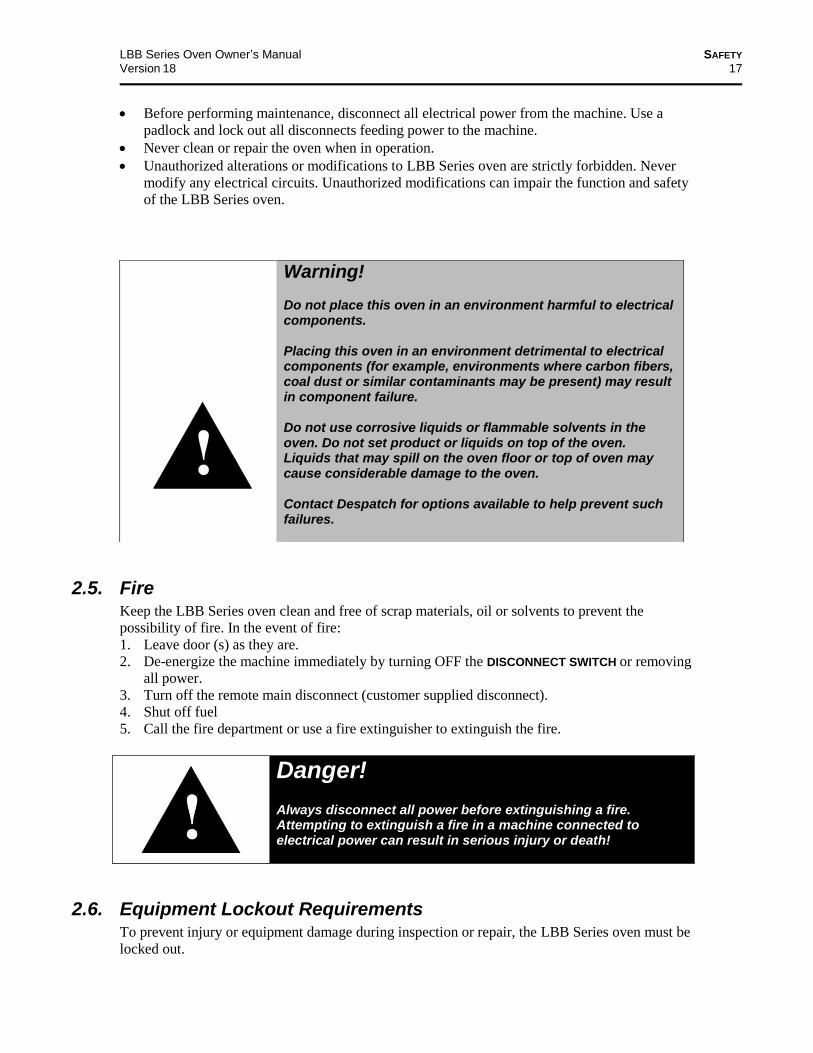
2.5. Fire Keep the LBB Series oven clean and free of scrap materials, oil or solvents to prevent the
possibility of fire. In the event of fire:
1. Leave door (s) as they are.
2. De-energize the machine immediately by turning OFF the DISCONNECT SWITCH or removing
all power.
3. Turn off the remote main disconnect (customer supplied disconnect).
4. Shut off fuel
5. Call the fire department or use a fire extinguisher to extinguish the fire.
Danger! Always disconnect all power before extinguishing a fire. Attempting to extinguish a fire in a machine connected to electrical power can result in serious injury or death!
2.6. Equipment Lockout Requirements To prevent injury or equipment damage during inspection or repair, the LBB Series oven must be
locked out.
Warning! Do not place this oven in an environment harmful to electrical components. Placing this oven in an environment detrimental to electrical components (for example, environments where carbon fibers, coal dust or similar contaminants may be present) may result in component failure. Do not use corrosive liquids or flammable solvents in the oven. Do not set product or liquids on top of the oven. Liquids that may spill on the oven floor or top of oven may cause considerable damage to the oven. Contact Despatch for options available to help prevent such failures.
SAFETY LBB Series Oven Owner’s Manual
18 Version 18
2.6.1. Emergency Stop
When a risk of personal injury or damage to the LBB Series oven exists, turn OFF the oven by
either the disconnect switch or removing/unplugging the cord. This shuts off all electrical power
to the oven.
2.7. Disconnecting Devices
2.7.1. Power Requirements
Despatch recommends the LBB Series Ovens have unobstructed access to a dedicated power
source.
Use a power stabilizer if voltage fluctuation is greater than ±10% nominal voltage fluctuation.
2.7.2. Disconnecting Hard-Wired Units
LBB permanently-connected (hard-wired) ovens include models LBB1-69, LBB2-12, LBB2-18
and LBB2-27. Permanently-connected and multi-phased equipment must employ a switch or
circuit-breaker as means for disconnection.
Notice
For permanently-connected equipment, installation instructions must specify a switch or circuit-breaker be included during the facility oven installation for complete isolation.
The disconnecting device must be installed in close proximity to the equipment and within easy
reach of the operator. The disconnecting device must be marked as the disconnecting device for
the equipment. If the unit is equipped with an ON/OFF switch, mark the ON/OFF position
clearly.
Follow local codes and requirements for installing and using disconnect switches.
LBB Series Oven Owner’s Manual SAFETY
Version 18 19
Danger! Keep switch or circuit-breaker in building installation close to the equipment, within easy reach of the operator and clearly marked.
2.7.3. Disconnecting Corded Units
LBB cord-connected ovens includes model LBB1-23. To disconnect a corded unit, unplug the
cord from the power source.
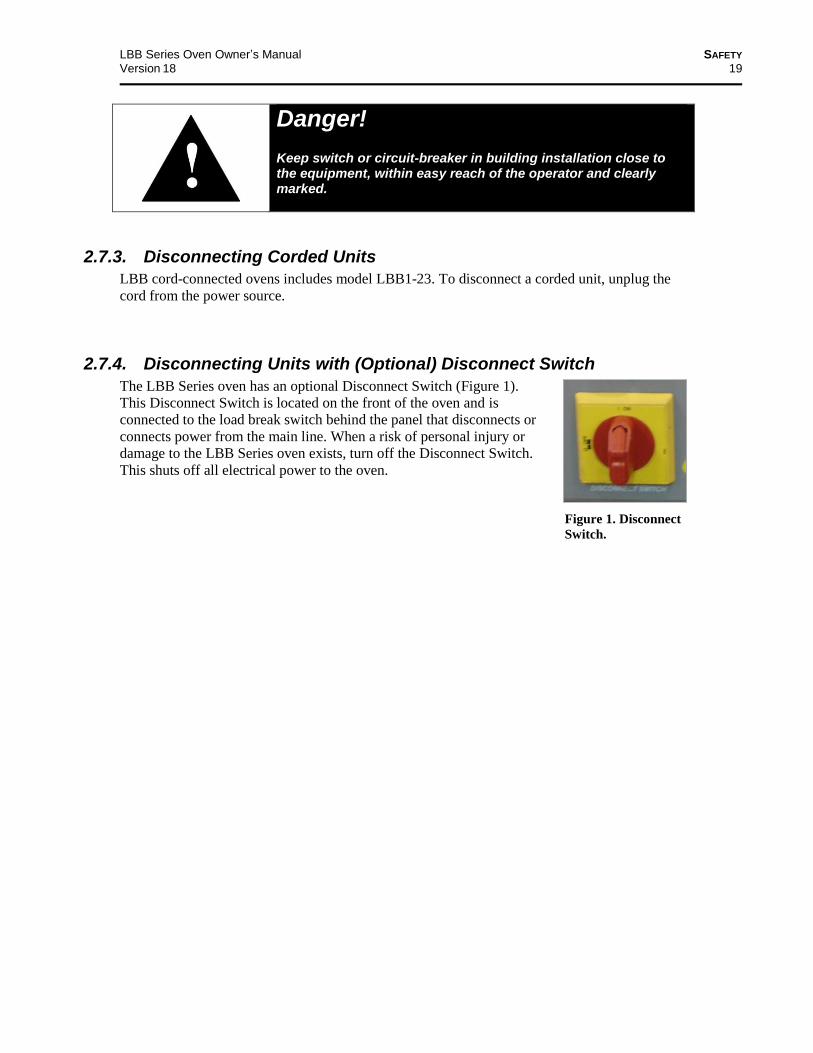
2.7.4. Disconnecting Units with (Optional) Disconnect Switch
The LBB Series oven has an optional Disconnect Switch (Figure 1).
This Disconnect Switch is located on the front of the oven and is
connected to the load break switch behind the panel that disconnects or
connects power from the main line. When a risk of personal injury or
damage to the LBB Series oven exists, turn off the Disconnect Switch.
This shuts off all electrical power to the oven.
Figure 1. Disconnect
Switch.
THEORY OF OPERATION LBB Series Oven Owner’s Manual
20 Version 18
Exhaust
Heater Recirculation Fan
3. Theory of Operation
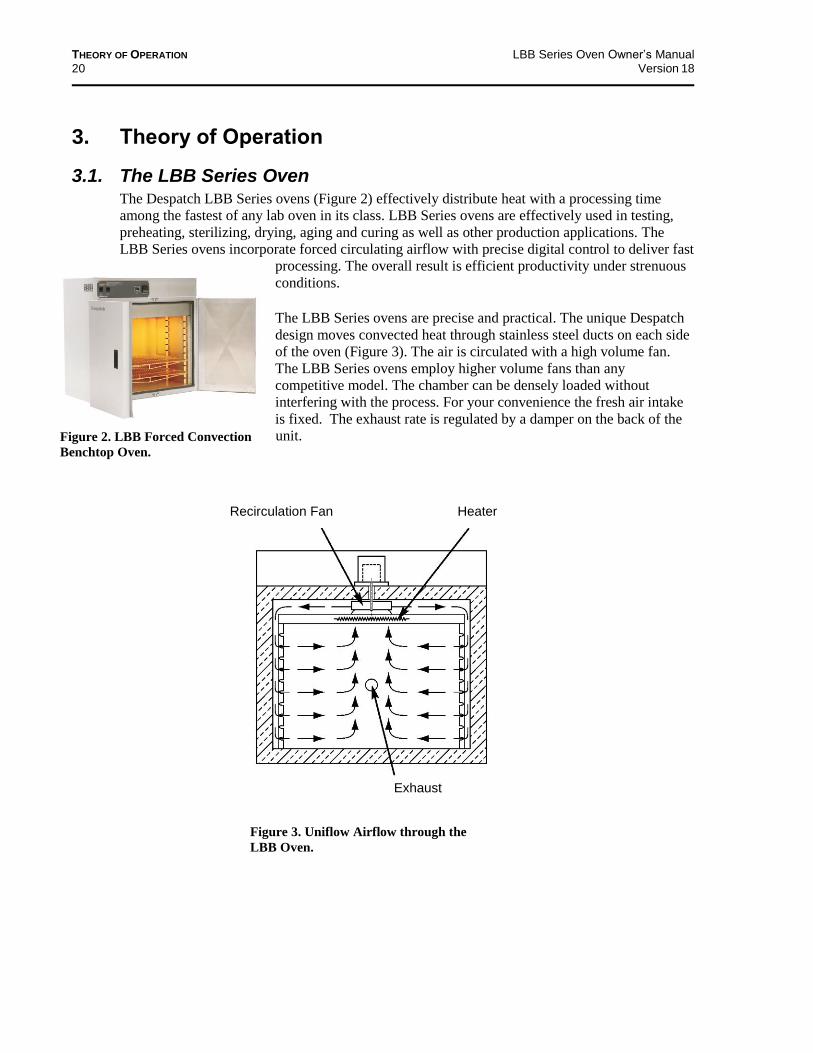
3.1. The LBB Series Oven The Despatch LBB Series ovens (Figure 2) effectively distribute heat with a processing time
among the fastest of any lab oven in its class. LBB Series ovens are effectively used in testing,
preheating, sterilizing, drying, aging and curing as well as other production applications. The
LBB Series ovens incorporate forced circulating airflow with precise digital control to deliver fast
processing. The overall result is efficient productivity under strenuous
conditions.
The LBB Series ovens are precise and practical. The unique Despatch
design moves convected heat through stainless steel ducts on each side
of the oven (Figure 3). The air is circulated with a high volume fan.
The LBB Series ovens employ higher volume fans than any
competitive model. The chamber can be densely loaded without
interfering with the process. For your convenience the fresh air intake
is fixed. The exhaust rate is regulated by a damper on the back of the
unit.
Figure 2. LBB Forced Convection
Benchtop Oven.
Figure 3. Uniflow Airflow through the
LBB Oven.

LBB Series Oven Owner’s Manual THEORY OF OPERATION
Version 18 21
3.1.1. Oven Theory
The LBB Series forced circulating oven uses fans to circulate air through the chamber. A
circulating oven is a much more efficient and uniform oven than a gravity-convection oven due to
the constant air movement. Soaking at a desired setpoint still depends on a number of parameters
including chamber area, load mass, the ability to absorb heat and the exhaust rate. But soak times
with a forced circulating oven may be shortened.
The LBB Series oven is capable of heating to 204°C (400°F). The oven uses a
microprocessor-based digital control to display the actual chamber temperature at the sensing
point. The temperature sensor is located to optimize control action for the entire chamber for
various load conditions. The control display may fluctuate a few degrees around the setpoint,
reflecting temperature changes at the sensor location. However, overall chamber temperature
remains stable. The strategic location of the sensor compensates for delays in heat convection and
enhances the performance and temperature control of the oven. The oven has been designed for
an overall result of quality productivity where fast processing and versatility are critical.
3.2. Control Systems
3.2.1. Primary Control Instrument
The LBB Series oven is equipped with a
microprocessor-based digital control instrument
configured as a proportional controller and set to
its optimum operating values (Figure 4). Initially
the control instrument allows the heater to
operate at full power. As the actual oven
temperature reaches the setpoint, the control
instrument cycles the heater on and off,
minimizing process temperature fluctuations.
Table 2 provides explanation for working with
the control instrument.
Warning! Do not remove the hat bracket as it distributes exhaust air and protects the exhaust opening from being completely covered.
Figure 4. LBB Series Oven Primary Control Instrument
THEORY OF OPERATION LBB Series Oven Owner’s Manual
22 Version 18
Table 2. Control Instrument Explanations.
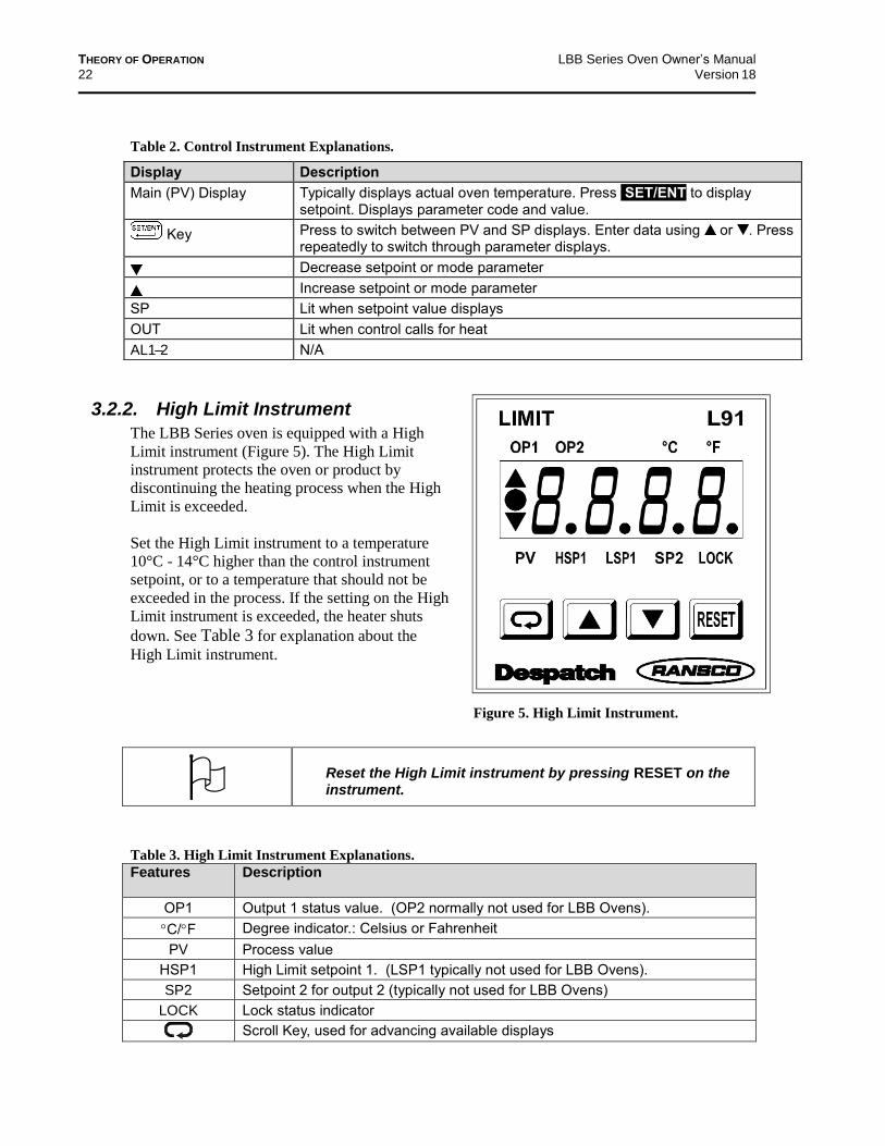
3.2.2. High Limit Instrument
The LBB Series oven is equipped with a High
Limit instrument (Figure 5). The High Limit
instrument protects the oven or product by
discontinuing the heating process when the High
Limit is exceeded.
Set the High Limit instrument to a temperature
10°C - 14°C higher than the control instrument
setpoint, or to a temperature that should not be
exceeded in the process. If the setting on the High
Limit instrument is exceeded, the heater shuts
down. See Table 3 for explanation about the
High Limit instrument.
Table 3. High Limit Instrument Explanations.
Features
Description
OP1 Output 1 status value. (OP2 normally not used for LBB Ovens).
C/F Degree indicator.: Celsius or Fahrenheit
PV Process value
HSP1 High Limit setpoint 1. (LSP1 typically not used for LBB Ovens).
SP2 Setpoint 2 for output 2 (typically not used for LBB Ovens)
LOCK Lock status indicator
Scroll Key, used for advancing available displays
Display Description
Main (PV) Display Typically displays actual oven temperature. Press SET/ENT to display setpoint. Displays parameter code and value.
Key Press to switch between PV and SP displays. Enter data using or . Press repeatedly to switch through parameter displays.
Decrease setpoint or mode parameter
Increase setpoint or mode parameter
SP Lit when setpoint value displays
OUT Lit when control calls for heat
AL1 –2 N/A
Reset the High Limit instrument by pressing RESET on the instrument.
Figure 5. High Limit Instrument.
LBB Series Oven Owner’s Manual THEORY OF OPERATION
Version 18 23
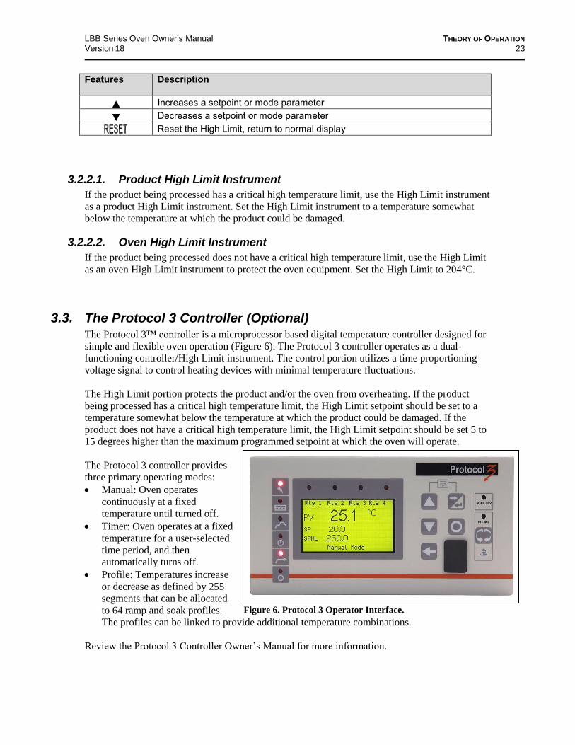
Figure 6. Protocol 3 Operator Interface.
Features
Description
Increases a setpoint or mode parameter
Decreases a setpoint or mode parameter
Reset the High Limit, return to normal display
3.2.2.1. Product High Limit Instrument
If the product being processed has a critical high temperature limit, use the High Limit instrument
as a product High Limit instrument. Set the High Limit instrument to a temperature somewhat
below the temperature at which the product could be damaged.
3.2.2.2. Oven High Limit Instrument
If the product being processed does not have a critical high temperature limit, use the High Limit
as an oven High Limit instrument to protect the oven equipment. Set the High Limit to 204°C.
3.3. The Protocol 3 Controller (Optional) The Protocol 3™ controller is a microprocessor based digital temperature controller designed for
simple and flexible oven operation (Figure 6). The Protocol 3 controller operates as a dual-
functioning controller/High Limit instrument. The control portion utilizes a time proportioning
voltage signal to control heating devices with minimal temperature fluctuations.
The High Limit portion protects the product and/or the oven from overheating. If the product
being processed has a critical high temperature limit, the High Limit setpoint should be set to a
temperature somewhat below the temperature at which the product could be damaged. If the
product does not have a critical high temperature limit, the High Limit setpoint should be set 5 to
15 degrees higher than the maximum programmed setpoint at which the oven will operate.
The Protocol 3 controller provides
three primary operating modes:
Manual: Oven operates
continuously at a fixed
temperature until turned off.
Timer: Oven operates at a fixed
temperature for a user-selected
time period, and then
automatically turns off.
Profile: Temperatures increase
or decrease as defined by 255
segments that can be allocated
to 64 ramp and soak profiles.
The profiles can be linked to provide additional temperature combinations.
Review the Protocol 3 Controller Owner’s Manual for more information.

ASSEMBLY & SETUP LBB Series Oven Owner’s Manual
24 Version 18
4. Assembly & Setup Assembly and Setup provides directions for unpacking and installing your Despatch LBB Series
oven.
4.1. Unpack & Inspect the LBB Series Oven Remove all packing materials and thoroughly inspect the oven for any damage that might have
occurred during shipment.
Note whether the carton and plastic cover sheet inside carton are still in good condition
Observe all outside surfaces and corners of the oven for scratches and dents
Check oven controls and indicators for normal movement, bent shafts, cracks, chips or
missing parts such as knobs and lenses
Check the door and latch for smooth operation
Check the packing list to ensure you received all the specified components of the oven
system. The base oven includes:
One (1) Despatch oven
One (1) Instruction manual (CD)
Two (2) Shelves
4.1.1. If Damaged During Shipping
If damage occurred during shipping:
Contact the shipper immediately and file a written damage claim.
Contact Despatch Industries (1-800-473-7373 or 1-952-469-8230 or [email protected])
to report your findings and to order replacement parts for those damaged or missing. Send a
copy of your filed damage claims to Despatch industries (Despatch Industries, 8860 207th
Street, Lakeville, MN 555044, USA).
4.2. Set-up the LBB Series Oven
4.2.1. Select Oven Location/Operating Environment
The Despatch LBB Series oven is designed to operate in an industrial setting. Despatch
recommends the following environmental operating guidelines:
1. Place the oven on a flat, level solid foundation.
2. Do not expose the oven to excessive external vibration.
3. Do not remove electrical cabinet covers.
4. Where excessive particulate matter is present, such as on a construction site or coal
processing, Despatch recommends periodic (usually monthly) cleaning of all electrical
compartments.
5. Ensure the power supply meets Despatch specifications. If the facility power supply is not
stable, Despatch recommends a line conditioner.
LBB Series Oven Owner’s Manual ASSEMBLY & SETUP
Version 18 25
4.2.2. Set-up Procedure
1. Place oven on bench top or optional cabinet base.
a. Ensure a minimum of six (6) inches (15.3 cm) clearance in the rear of oven to provide
proper ventilation. The oven may be placed next to another cabinet, or next to another
oven, with three (3) inch (7.6 cm) clearance (the doors will still open).
b. Ensure oven is level and plumb for proper heat distribution and operation of all
mechanical components.
2. Identify correct power source indicated on the specification nameplate.
3. Plug or hardwire oven directly to the electric supply.
4.2.3. Wiring & Power Connections
Read the Model LBB nameplate (top of oven or top of control area under the door) for proper power requirements before proceeding with wiring and power connections (Figure 7).
Danger! All grounding and safety equipment must be in compliance with applicable codes, ordinances and accepted safe practices.
Warning! All grounding and safety equipment must be in compliance with applicable codes, ordinances and accepted safe practices.
Warning! Do not use the oven in wet, corrosive or explosive atmospheres unless this oven is specifically designed for a special atmosphere.
ASSEMBLY & SETUP LBB Series Oven Owner’s Manual
26 Version 18
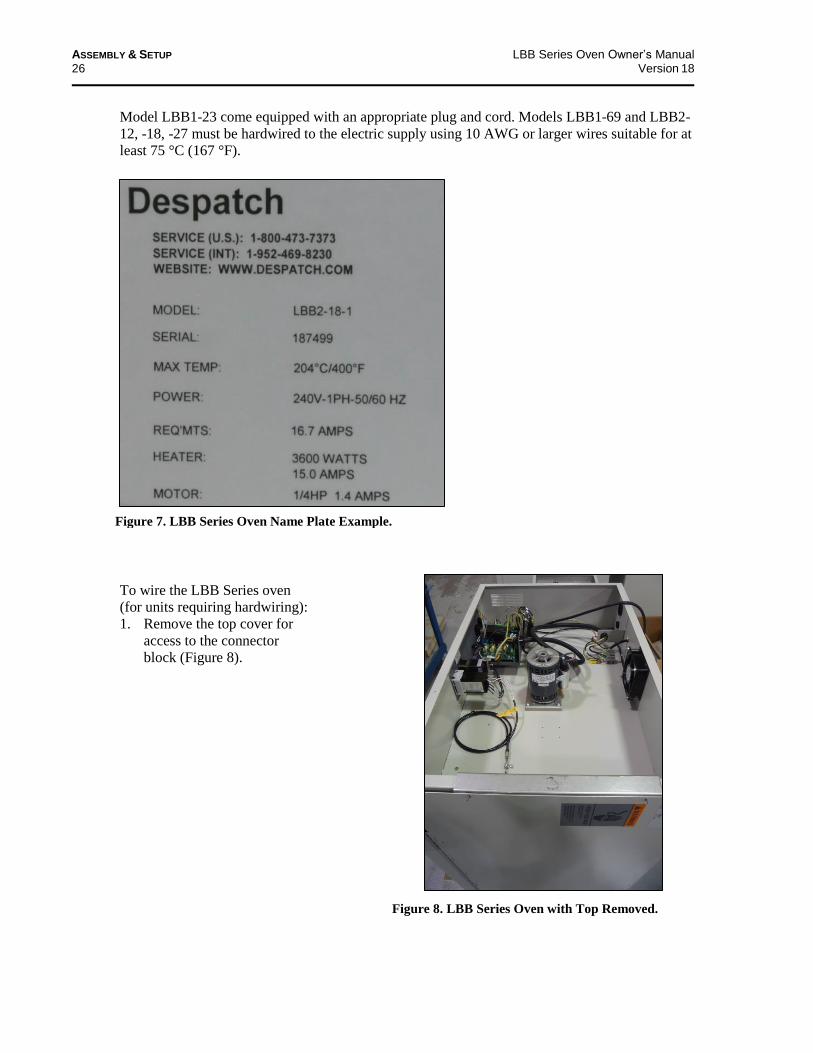
Model LBB1-23 come equipped with an appropriate plug and cord. Models LBB1-69 and LBB2-
12, -18, -27 must be hardwired to the electric supply using 10 AWG or larger wires suitable for at
least 75 °C (167 °F).
To wire the LBB Series oven
(for units requiring hardwiring):
1. Remove the top cover for
access to the connector
block (Figure 8).
Figure 7. LBB Series Oven Name Plate Example.
Figure 8. LBB Series Oven with Top Removed.

LBB Series Oven Owner’s Manual ASSEMBLY & SETUP
Version 18 27
2. Run the wire through the rear access
hole (Figure 9) and connect the
appropriate wires at the connector
block (Figure 10).
Figure 9. Wiring Access through Rear of Oven.
Figure 10. Close-up of Connector Block.
ASSEMBLY & SETUP LBB Series Oven Owner’s Manual
28 Version 18
5. Operation
Users and operators of this oven must comply with operating procedures and training of operating personnel as required by the Occupational Safety and Health Act (OSHA) of 1970, Section 5 and relevant safety standards, and other safety rules and regulations of state and local governments. Refer to the relevant safety standards in OSHA and National Fire Protection Association (NFPA), Section 86 of 1990.
5.1. Load Oven
Despatch Industries cannot be responsible for either the process or process temperature used, or for the quality of the product being processed. The purchaser and operator are responsible ensure that the product undergoing processing in a Despatch oven is adequately protected from damage. Carefully following the instructions in this manual will help the purchaser and operator in fulfilling that responsibility.
Warning! Do not use corrosive liquids or flammable solvents in the oven. Do not set product or liquids on top of the oven. Liquids that may spill on the oven floor or top of oven may cause considerable damage to the oven.
Warning! Do not use the oven in wet, corrosive or explosive atmospheres unless this oven is specifically designed for a special atmosphere.
Warning! Never operate the LBB Series oven at a temperature in excess of the maximum operating temperature of 204°C (400°F).
LBB Series Oven Owner’s Manual OPERATION
Version 18 29
The two shelves are designed to be pulled out about halfway without tipping. Do not overload the
shelves (Refer to Support Capacity listed in Section 1.5.3). Distribute the workload evenly so
airflow is not restricted. Do not overfill your oven. The workload should not take up more than
two-thirds of any dimension of the inside cavity.
For units where the controls are on the bottom, avoid spilling on the heater elements or oven floor
when loading the oven. Do not place the load on the oven floor plate. Placing the load on the
oven floor may cause the load to heat unevenly and the weight may cause shorting out of the
heater elements. Use the shelves provided.
Caution! Always place loads on the shelves provided to avoid possible uneven heating and damage to the oven.
5.2. Pre-Startup Checklist
Warning! Do not use flammable solvent or other flammable material in this oven. Do not process closed containers of any substance or liquid in this oven because they may explode under heat.
□ Know the system. Read this manual carefully. Make use of its instructions and explanations.
Safe, continuous, satisfactory, trouble-free operation depends primarily on your degree of
understanding the system and your willingness to keep all parts in proper operating condition.
□ Check line voltage. Voltage must correspond to nameplate requirements of motors and
controls. A wrong voltage can result in serious damage. Refer to Section 1.5.4 for more
information.
□ Check fresh air and exhaust openings. Do not be careless about restrictions in and around the
fresh air and exhaust openings and stacks. Under no condition can they be permitted to
become so filled with dirt that they reduce airflow. Refer to the Set-up instructions (4.2.2) for
more information.
□ Ventilation. An exhaust opening resides in the rear of the unit.
□ Helpful hints:
For drying ovens, open vent to prevent buildup of moisture
The exhaust vent may have to be closed to reach the maximum temperature of 204°C, especially if operating on 208 volts. The exhaust vent may need to be opened to operate properly at the lower range of the oven's design.

OPERATION LBB Series Oven Owner’s Manual
30 Version 18
For sample heating, close vent when no ventilation is required
5.3. Operating Procedure—Standard Control Instrument
See Protocol 3 Controller Owner's Manual for operating procedures for optional Protocol
3 control instrument.
Warning! Do not use flammable solvent or other flammable material in this oven. Do not process closed containers of any substance or liquid in this oven because they may explode under heat.
For fastest oven heat-up time, close the exhaust vent. After the desired temperature is reached, adjust the vent as needed. Caution, damper may be hot.
5.3.1. Start Oven
1. Turn POWER ON (Figure 11). The circulating fan will start.
2. Set exhaust vent to desired opening by adjusting the damper at the rear of the oven (Figure
12).
a. Adjust the vent for maximum performance at various operating temperatures.
3. Enter desired setpoint on the High Limit instrument.
a. Set the High Limit instrument to a temperature 10° to 14°C higher than the desired
setpoint or to a temperature that should not be exceeded in the process.
b. If the LOCK on the High Limit instrument is lit, press and hold the RESET for four (4)
seconds to enable ▲ and ▼.
c. Press . HSP1 will light.
d. Use ▲ and ▼ to set the High Limit temperature.
e. Press RESET (or ) once to enter the value and return to the process variable PV
mode.
4. Enter setpoint on the Control instrument.
a. Press until the SP lights.
b. Use ▲ and ▼ to set the operating temperature.
If the High Limit instrument is exceeded, the heater shuts down. Reset the High Limit instrument by pushing RESET on the High Limit instrument.

LBB Series Oven Owner’s Manual OPERATION
Version 18 31
c. Press to enter the setpoint.
d. Press again to display the process temperature.
5. Turn HEATER ON.
a. When the process value on the Control instrument reaches setpoint, OUT cycles ON and
OFF to maintain the temperature setpoint.
b. OUT lights when the control calls for heat.
6. Turn HEATER OFF after the heating cycle is complete.
7. Do not turn the fan OFF until the oven chamber temperature is below 100◦C (212
◦F).
Warning! Damper may be hot at elevate temperatures.
Figure 11. LBB Series Oven Control Panel.
Figure 12. Adjust Damper to Set Exhaust Vent by rotating the outer component.
OPERATION LBB Series Oven Owner’s Manual
32 Version 18
5.4. Working with the Control Instrument
Danger! Failure to heed warnings in this instruction manual and on the oven could result in personal injury, property damage or death.
The LBB Series oven is factory tested and the controls have been factory-set for normal operating
conditions.
In most applications it is not necessary to alter the oven’s settings, except for Setpoint.
This section contains information for changing setpoints, programming modes, and displaying
temperature, along with instructions for oven zone calibration, parameter setup mode and
troubleshooting.
5.4.1. Change Setpoint
Warning! Never operate oven at a temperature in excess of the maximum operating temperature of 204°C (400°F).
To enter Setpoint on the Control instrument:
1. Press . SP will light.
2. Use ▲ and ▼ to set the operating temperature.
a. The right decimal point LED will flash indicating the Setpoint is being changed.
b. The right decimal point LED stops flashing when the new value has been entered.
3. Press to enter the Setpoint.
4. Press again to display the process temperature.
LBB Series Oven Owner’s Manual OPERATION
Version 18 33
5.4.2. Control Instrument Parameter Programming Mode
Warning! Changing program parameters alters the function of the Control. Proceed carefully and fully understand each parameter before changing that parameter.
Control instrument parameters are set through the Operating and Set-up modes. In most
applications, it is not necessary to alter the oven settings. The following instructions describe how
to access, view and if desired, change the parameters. Once the Operating and Set-up modes are
accessed, SP will start blinking on and off. Table 4 and Table 5 explain the Operating and Set-up
Mode parameters.
The Control Instrument will not allow the display to be altered improperly. The Control
Instrument will automatically exit the Parameter Programming mode if no keys are pressed for
about two (2) minutes.
5.4.2.1. Entering Control Instrument Set-up and Configuration Mode
To enter the Operating and Set-up Mode (Figure 4):
1. Press for three (3) seconds.
2. Press until the desired parameter displays. See Table 4 for more information.
3. Press ▲ or ▼ to display the value.
4. Use ▲ or ▼ to move to the desired setting.
5. Press to enter the value.
6. Press and hold for three (3) seconds to return to the display mode.
Table 4. Control Instrument Set-up Parameters.
Code Name Description Settings
CtL
Control Mode
Determines whether controller functions as a time proportional or an on/off control.
PID
At Auto-tuning OFF for PID tuning, ON for controller to tune process OFF
P Proportional Band
Expressed in degrees, value determines the band width on both sides of the setpoint within which the control provides proportional control.
4
(8 if F)*
I Integral Time
Expressed in seconds, value corrects for errors in actual temperature versus the setpoint
15
d Derivative Time
Expressed in seconds, value shows the effect of the derivative time is in direct proportion to the time setting
0
Ct Cycle Time Expressed in seconds, value shows total time for one ON/OFF cycle of the controller output during the proportional action
1
FL Input Filter Expressed in seconds. Use this function when the PV may fluctuate greatly (for example, when an input signal contains noise)
0

OPERATION LBB Series Oven Owner’s Manual
34 Version 18
Code Name Description Settings
bS PV Bias (Offset)
Expressed in degrees, from –199 to 999. Use this parameter to calibrate oven temperature.
0
LoC Key Lock Provides levels of access to the controller:
0 = No key lock, full access to controller
1 = Prevents changing of all parameters except setpoint
2 = Prevents all parameters from being changed including the setpoint
-1 = Set to enter the Set-up parameter setting display.
1
nr Manual Reset
Only when I & d are OFF. Expressed in percent. Controller outputs this value when process variable equals setpoint, but only if I = 0.
N/A
HyS Hysteresis Only when CtL is OFF, change CtL to PID) Expressed in degrees. When CtL = OFF, this value determines the change in temperature needed to turn controller output from full OFF to full ON.
N/A
*If P is not displayed the Control Mode (CtL) must be first set to PID.
5.4.2.2. Control Instrument Operating Mode Notes
The controller is factory set to LoC=1 (allowing only the setpoint to be changed). This setting
prevents inadvertent changing of control parameters.
If necessary to alter control parameters, change the LoC=1 to LoC=0. See Section 5.4.2.1 for
more information.
When LoC = -1, parameters are displayed in the order shown in the Set-Up Parameters table
(Table 5).
Note: If unable to change setup parameters:
o Change the LoC = 0
o Press the until LoC appears again
o Change LoC = -1
o Press the
Table 5. Control Instrument Configuration Parameters.
Code Name Description Settings
In Input Type Set for type of input and whether PV is in °C or °F
5
(35 if F)
SPH Setpoint High
The maximum setpoint limit for oven. The user cannot set the setpoint above the maximum setpoint.
204 (400 if F)
SPL
Setpoint Low The minimum setpoint limit of oven. The user cannot
change the setpoint below this lower setpoint limit.
0 (32 if F)
SC
Super Function
Despatch recommends leaving the SC feature OFF OFF
dr
Direct/Reverse Action
Direct/Reverse action. This value is set for 0 (reverse action).
0
dSP
PV/SP Display Priority of PV/SP display. This parameter either
displays the PV (process variable) or SP (setpoint).
0 = process variable
1 = setpoint
0
LBB Series Oven Owner’s Manual OPERATION
Version 18 35
5.4.3. Change Control Instrument Display from Centigrade to Fahrenheit
Warning! Program parameter changes will alter the function of the Control instrument. Proceed carefully and fully understand each parameter before changing that parameter.
Configure the Control instrument for either °C or °F. Use the following steps to change control
from displaying °C to °F:
1. Press and hold for three (3) seconds.
a. CtL displays.
b. SP will flash indicating the Control Instrument has entered Operating Parameter mode.
2. Press until LoC displays.
3. Press or to enter parameter.
4. Press the to set the value to –1.
a. SP will flash rapidly indicating the Control Instrument has entered Set-Up Parameter
mode.
5. Press to enter the value.
a. In displays.
b. Press the or to enter the parameter.
c. Note: If unable to change setup parameters, follow this procedure:
i. Press and hold for three (3) seconds to return to the operation mode.
ii. Change the LoC to 0.
iii. Press until LoC displays.
iv. Change LoC to -1.
v. Press .
6. Enter the value 35.
a. The right decimal point LED will flash indicating that the setpoint is being changed.
b. The decimal will stop flashing when the new value has been entered.
c. Press to enter the value.
7. Press until SPH displays.
a. Press or to enter the desired parameter.
8. Enter a value of 400.
a. Press to enter the value.
9. Repeat steps 7-8 for SPL .
10. Enter a value of 32.
11. Press and hold the for three (3) seconds to return to the operation mode.
a. The control now reads in degrees Fahrenheit.
b. Enter the desired setpoint.
12. Re-enter parameters form table 4 (note: this action defaults settings from lower level to high
level)
Refer to Table 5 to change tuning parameters, if necessary.
OPERATION LBB Series Oven Owner’s Manual
36 Version 18
To change from Fahrenheit to Centigrade, repeat the steps in Section 5.4.3 using In = 5, SPH = 204, SPL = 0
5.4.4. Oven Zone Calibration
The Control instrument has been factory-tested and calibrated. Under normal operating
conditions, recalibration should not be necessary. However, to recalibrate the Control Instrument
for a specific operating condition, follow the instructions below.
Warning! Changing program parameters alters the function of the Control. Proceed carefully and fully understand each parameter before changing that parameter.
1. Required Equipment: Temperature measuring device with a compatible temperature sensor.
2. Verify that bS (PV Bias) programmed in the Control instrument is set to 0. For more
information on programming parameters refer to Section 5.4.2.1.
3. Locate the temperature sensor of the temperature measuring device at the center of the
chamber.
Load the chamber with a standard amount of product to simulate a specific operation condition.
4. Operate the oven until it reaches the desired operating temperature and the Control instrument
is regulating.
a. It will take several minutes for the unit to stabilize at the controlled temperature.
b. Allow at least 30 minutes of operation at the stabilized temperature before proceeding.
5. Subtract the average controlled temperature (value appearing on the Control instrument
display) from the actual oven temperature (value appearing on the temperature measuring
device display).
a. Note that the Control instrument and the temperature sensing device must be in the same
scale (C or F).
LBB Series Oven Owner’s Manual OPERATION
Version 18 37
5.4.5. Set the High Limit
Danger! Failure to heed warnings in this instruction manual and on the oven could result in personal injury, property damage or death.
The oven has been factory-tested with the High Limit instrument factory-preset for normal
operating conditions. In most applications, it will not be necessary to alter the oven's settings,
except for the Setpoint. This section contains information and reference material to change
Setpoint, access the Set-up mode and change display between °C and °F.
The High Limit instrument was carefully programmed at the factory using the Operating and Set-
up mode. The parameters that may be accessed include; display functions, and thermocouple
selection.
5.4.5.1. Change the High Limit Instrument Setpoint
Warning! Never operate oven at a temperature in excess of the maximum operating temperature of 204°C (400°F).
Enter setpoint on the High Limit instrument. Set High Limit instrument to a temperature 10°C to
14°C higher than the setpoint or to a temperature that should not be exceeded in the process.
1. If on the High Limit instrument is lit, press and hold for four (4) seconds to
enable and .
2. Press , HSP1 will light.
3. Use and to set High Limit temperature.
4. Press or once to return (also enters the value) to the process variable PV mode.
5. If the High Limit instrument is exceeded the heater will shut down.
6. Reset the High Limit instrument by pushing on the High Limit instrument.
5.4.6. High Limit Instrument Parameter Setup Mode
Warning! Changing program parameters alters the function of the High Limit. Proceed carefully and fully understand each parameter before changing that parameter.

OPERATION LBB Series Oven Owner’s Manual
38 Version 18
Set High Limit instrument parameters using the Operating and Set-up modes (Section 5.4.2.1).
See section 5.4.4. to calibrate High Limit, only use SHif parameter. In most applications, it is not
necessary to alter the oven settings. The following instructions describe how to access, view and,
if desired, change the parameters.
If the on the High Limit instrument is lit, press and hold for four (4) seconds to enable
and . The High Limit instrument will automatically exit Setup mode if no keys are pressed
for about two (2) minutes.
1. Press and hold for four (4) seconds to enter Setup mode.
2. Press until desired parameter displays. See the Setup Parameter Table for more
information.
a. The display will alternate between the parameter name and value.
b. Use or to move to the desired setting.
c. Press to the value and advance to the next parameter.
3. To leave setup parameters press . The High Limit instrument automatically exits Setup
mode if no keys are pressed for about two (2) minutes.
5.4.7. High Limit Instrument Setup Parameters
Table 6 explains the High Limit instrument setup parameters.
When changing between centigrade and Fahrenheit, the setup parameters Filt, o1.Hy, HSP.L and HSP.H settings convert automatically.
Table 6. High Limit instrument Setup Parameters.
Code Name Description Settings
inPt Input type Select thermocouple type. LBB Series ovens use type J thermocouples
J_tC
unit Process unit. Select between °C and °F for reading process temperature
C (or F)
rESo Display resolution.
Select location of decimal point on process-related parameters
No.dP
SHif PV shift value (offset).
Moves the display temperature to the oven temperature
0
Filt PV filter. If the process value is unstable to read, increasing this value steadies the input signal.
0
out1 Output 1 function.
Function of the output. Must be set to Hi. for High Limit control.
Hi.
o1.Hy Output 1 hysteresis value.
Amount of degrees the temperature must be below the setpoint temperature before the High Limit can be reset 2.0

LBB Series Oven Owner’s Manual OPERATION
Version 18 39
HSP.L Lower limit of HSP1.
Minimum temperature setting for the High Limit
0 (32 if F)
Code Name Description Settings
HSP.H Upper limit of HSP1.
Maximum temperature setting for the High Limit 204 (400 if
F)
out2 Second output Despatch does not use this function None
diSP Normal display format.
Used to select the display in normal condition:
PV = Process Value
SP! = High Limit Setpoint
SAFE = The word “safe” in normal condition
PV
PuHi Process value high
Read-Only Data: Maximum process value since last UNLOCK operation.
None
PuLo Process value low
Read-Only Data: Minimum process value since last UNLOCK operation.
None
t.Abn Abnormal time Total accumulated minutes of abnormal conditions since last UNLOCK operation.
None
5.4.8. Change High Limit instrument Display from Centigrade to Fahrenheit
Warning! Changing program parameters alters the function of the Control. Proceed carefully and fully understand each parameter before changing that parameter.
Configure the High Limit instrument for either °C or °F. Use the following steps to change High
Limit instrument from displaying °C to °F (and for changing back):
1. If on the High Limit instrument is lit, press and hold for four (4) seconds to
enable and .
2. Press and hold for four (4) seconds to enter Setup mode.
3. Press until unit displays.
4. Display will alternate between parameters and settings
5. Use or to move to the desired setting.
6. Press to enter the value and advance to the next parameter.
7. Press to return the High Limit instrument to normal mode.
8. The High Limit instrument has been changed, enter the desired setpoint. 9. Lock turns back on automatically after approximately sixty (60) seconds.
5.5. Working with Optional Protocol 3 Controller Operating Modes Refer to the Protocol 3 Controller Owner’s Manual for specifics on working with the Protocol 3
controller.
MAINTENANCE LBB Series Oven Owner’s Manual
40 Version 18
6. Maintenance
Danger! Failure to heed warnings in this instruction manual and on the oven could result in personal injury, property damage or death.
Danger! Do not attempt any service on this oven before opening the main power disconnect switch.
6.1. Checklist
Keep equipment clean. Gradual dirt accumulation retards airflow. A dirty oven can result in
unsatisfactory operation such as unbalanced temperature in the work chamber, reduced
heating capacity, reduced production, overheated components. Keep the walls, floor and
ceiling of the oven work chamber free of dirt and dust. Floating dust or accumulated dirt may
produce unsatisfactory work results. Keep all equipment accessible. Do not permit other
materials to be stored or piled against it.
Protect controls against excessive heat—particularly controls, motors or other equipment
containing electronic components. Temperatures greater than 51.5°C (125°F) should be
avoided.
Establish maintenance and checkup schedules. Do this promptly and follow the schedules
Warning! Do not place this oven in an environment harmful to electrical components. Placing this oven in an environment detrimental to electrical components (for example, environments where carbon fibers, coal dust or similar contaminants may be present) may result in component failure. Do not use liquids in the oven. Do not set product or liquids on top of the oven. Liquids that may spill on the oven floor or top of oven may cause considerable damage to the oven. Contact Despatch for options available to help prevent such failures.
LBB Series Oven Owner’s Manual MAINTENANCE
Version 18 41
faithfully. Careful operation and maintenance will be more than paid for in continuous, safe
and economical operation.
Maintain equipment in good repair. Make repairs immediately. Delays may be costly in
added expense for labor and materials and in prolonged shut down.
Practice safety. Make it a prime policy to know what you are doing before you do it. Make
caution, patience, and good judgment the safety watchwords for the operation of your oven.
6.2. Lubrication Fan motor bearings are permanently lubricated. All door latches, hinges, door operating
mechanisms, bearing or wear surfaces should be lubricated to ensure easy operation.
6.3. Cleaning and Decontamination
6.3.1. Cleaning the LBB Series Oven
For best product results, clean the oven monthly. To clean the oven:
1. Wipe all surfaces with a moistened towel or use a neutral cleaning agent.
2. Use a moistened towel to remove cleaning agents when finished.
3. Dry oven completely before turning it on again.
Clean stainless steel surfaces quarterly. To clean stainless steel surfaces:
1. Wash steel surface using a polyurethane cloth or sponge with clean water and liquid
detergent.
Notice
Clean quickly for maximum surface protection. Using water that contains chlorine or hydrochloric acid to clean may damage the oven. Choose a neutral cleaning agent instead.
Warning! Do not clean oven without first disconnecting power.

MAINTENANCE LBB Series Oven Owner’s Manual
42 Version 18
6.3.2. Decontaminating the LBB Series Oven
Notice
Before using any cleaning or decontamination method except those recommended by the manufacturer, users should check with the manufacturer that the proposed method will not damage the equipment.
For best results, decontaminate the work zone daily.
1. Wipe all work surfaces with an appropriate disinfectant.
2. Use a neutral cleaning agent. Do not use acidic or chlorine cleaning detergents as they
may damage or corrode the oven.
If necessary, remove highly contaminated inner chamber parts for cleaning or exchange.
6.4. Routine Tests
Danger! Failure to heed warnings in this instruction manual and on the oven could result in personal injury, property damage or death.
Warning! Do not decontaminate oven without first disconnecting power. Ensure adequate personal safety while decontaminating oven.
Danger! Explosive gases may form during decontamination. Dry and ventilate oven before start-up to avoid explosions.
LBB Series Oven Owner’s Manual MAINTENANCE
Version 18 43
Test LBB Series oven functions regularly and carefully for best performance. Safety of personnel
and maintenance of your equipment may depend on the proper operation of any of the
temperature control functions.
6.4.1. Test Control Instrument
Test the Control instrument every 40 hours:
Check that the Control instrument OUT LED is cycling ON and OFF
Verify that the heater works
6.4.2. Test High Limit Instrument
Test the High Limit instrument every 40 hours. With the oven operating at a set temperature, set
High Limit instrument down to the setpoint operating temperature:
The High Limit instrument is tripped when OP1 lights
Push after adjusting the High Limit instrument back to a higher setting, or by letting
the oven temperature drop a few degrees based on the hysteresis value of the High Limit
instrument
6.5. Replacement Parts
Danger! Do not attempt any service on this oven before opening the main power disconnect switch or removing all power from the oven.
To order or return parts, contact Despatch Service and Technical Support. When returning parts, a
Despatch representative will provide an MRA (Material Return Authorization) number. Attach
the MRA number to the returned part for identification. When ordering parts, expedite the process
by having the model number, serial number and part number on hand.
Global Headquarters Contact Service & Technical
Support
Despatch Industries 8860 207th Street Lakeville, MN 55044 USA
International/Main: 1-952-469-5424 US toll free: 1-800-726-0110 Fax: 1-952-469-4513 [email protected] www.despatch.com
Service: 1-952-469-8230 US toll free: 1-800-473-7373 Fax: 1- 952-469-8193 Service @despatch.com
MAINTENANCE LBB Series Oven Owner’s Manual
44 Version 18
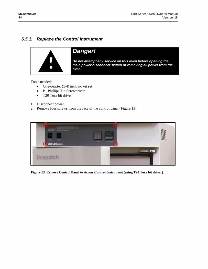
Figure 13. Remove Control Panel to Access Control Instrument (using T20 Torx bit driver).
6.5.1. Replace the Control Instrument
Danger! Do not attempt any service on this oven before opening the main power disconnect switch or removing all power from the oven.
Tools needed:
One-quarter (1/4) inch socket set
P1 Phillips Tip Screwdriver
T20 Torx bit driver
1. Disconnect power.
2. Remove four screws from the face of the control panel (Figure 13).
LBB Series Oven Owner’s Manual MAINTENANCE
Version 18 45
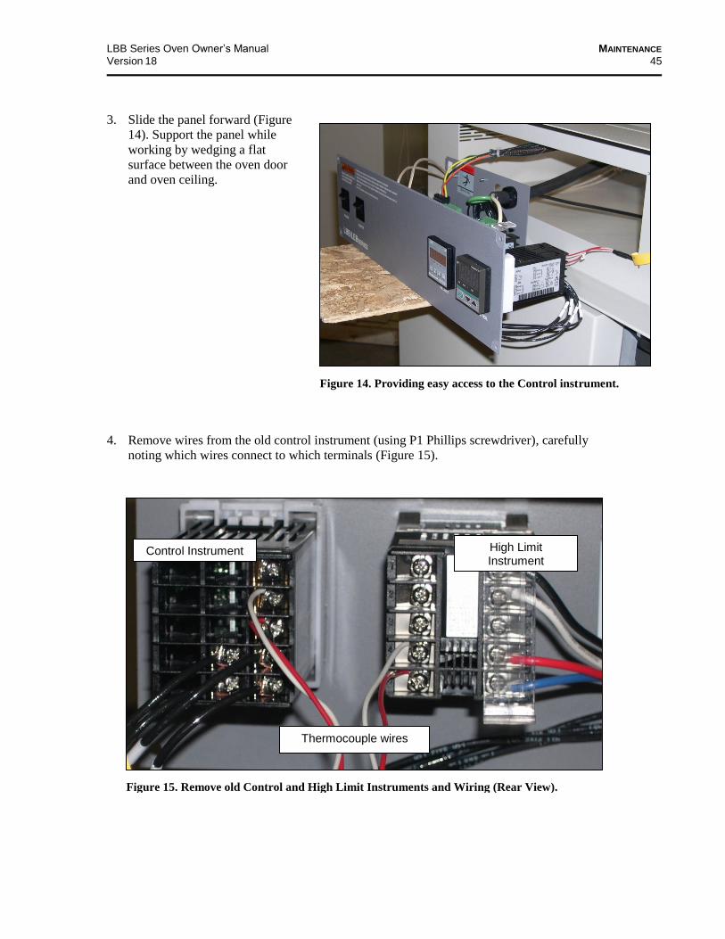
3. Slide the panel forward (Figure
14). Support the panel while
working by wedging a flat
surface between the oven door
and oven ceiling.
4. Remove wires from the old control instrument (using P1 Phillips screwdriver), carefully
noting which wires connect to which terminals (Figure 15).
Thermocouple wires
Control Instrument High Limit Instrument
Figure 15. Remove old Control and High Limit Instruments and Wiring (Rear View).
Figure 14. Providing easy access to the Control instrument.
MAINTENANCE LBB Series Oven Owner’s Manual
46 Version 18
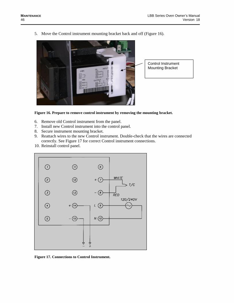
Control Instrument Mounting Bracket
Figure 16. Prepare to remove control instrument by removing the mounting bracket.
5. Move the Control instrument mounting bracket back and off (Figure 16).
6. Remove old Control instrument from the panel.
7. Install new Control instrument into the control panel.
8. Secure instrument mounting bracket.
9. Reattach wires to the new Control instrument. Double-check that the wires are connected
correctly. See Figure 17 for correct Control instrument connections.
10. Reinstall control panel.
Figure 17. Connections to Control Instrument.
LBB Series Oven Owner’s Manual MAINTENANCE
Version 18 47
6.5.2. Replace High Limit Instrument
Danger! Do not attempt any service on this oven before opening the main power disconnect switch or removing all power from the oven.
Tools needed:
One-quarter (1/4) inch socket set
Screwdriver
T20 Torx bit driver
1. Disconnect power.
2. Remove four screws from the face of the control panel (Figure 13).
3. Slide the panel forward (Figure 14).
4. Remove wires from the old High Limit instrument, carefully noting which wires connect to
which terminals (Figure 15).
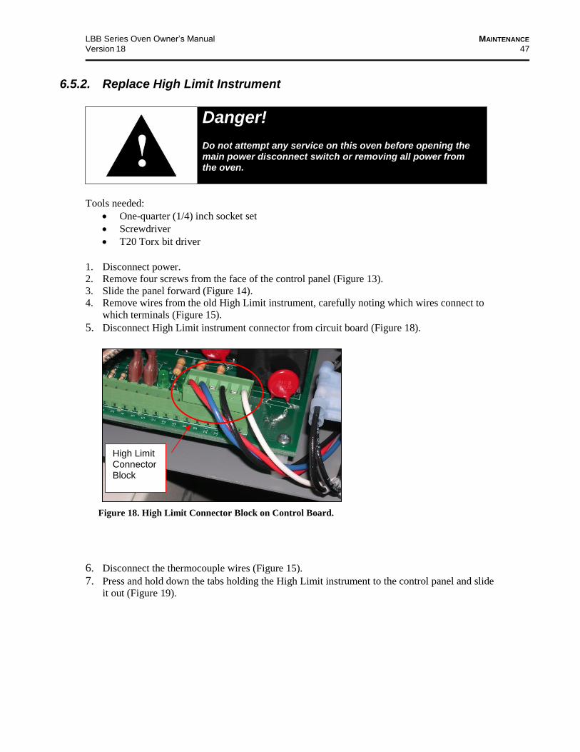
5. Disconnect High Limit instrument connector from circuit board (Figure 18).
6. Disconnect the thermocouple wires (Figure 15). 7. Press and hold down the tabs holding the High Limit instrument to the control panel and slide
it out (Figure 19).
High Limit Connector Block
Figure 18. High Limit Connector Block on Control Board.
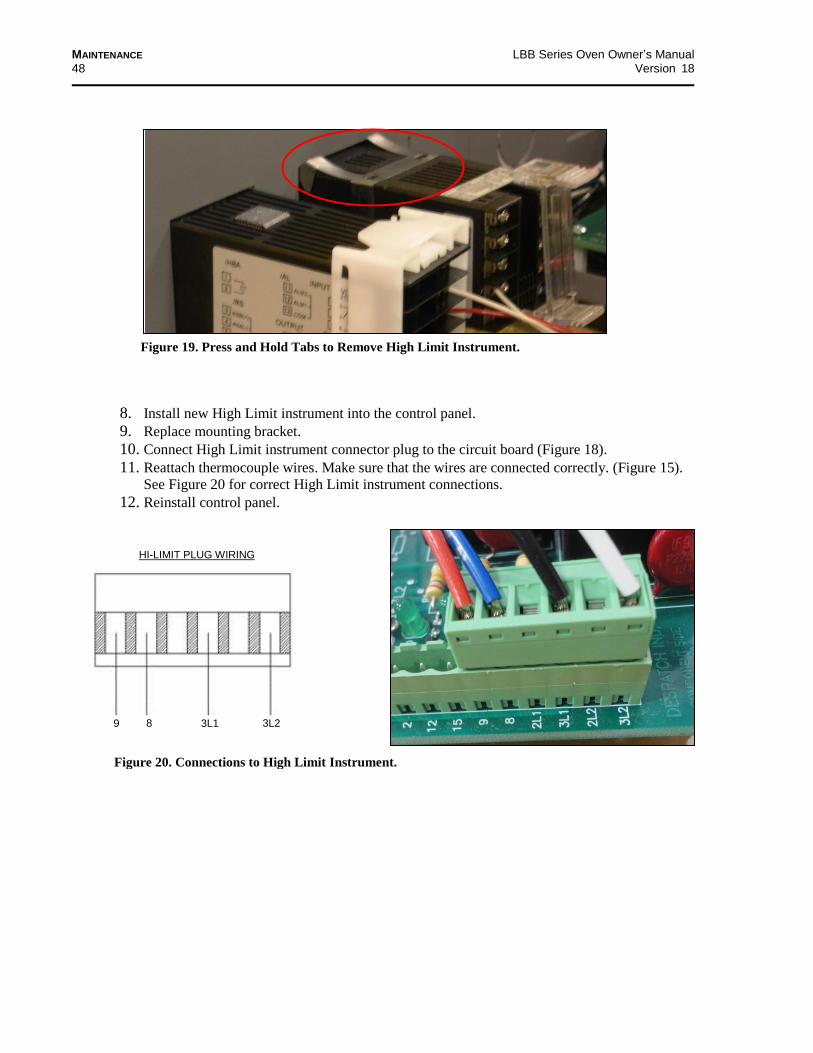
MAINTENANCE LBB Series Oven Owner’s Manual
48 Version 18
8. Install new High Limit instrument into the control panel. 9. Replace mounting bracket. 10. Connect High Limit instrument connector plug to the circuit board (Figure 18).
11. Reattach thermocouple wires. Make sure that the wires are connected correctly. (Figure 15).
See Figure 20 for correct High Limit instrument connections. 12. Reinstall control panel.
9 8 3L1 3L2
HI-LIMIT PLUG WIRING
Figure 19. Press and Hold Tabs to Remove High Limit Instrument.
Figure 20. Connections to High Limit Instrument.

LBB Series Oven Owner’s Manual MAINTENANCE
Version 18 49
6.5.3. Replace (Optional) Protocol 3 Controller
Refer to the Protocol 3 Owner’s Manual for instructions on replacing the Protocol 3 Controller.
6.5.4. Replace Heater Unit
Danger! Do not attempt any service on this oven before opening the main power disconnect switch or removing all power from the oven.
Tools needed:
Thin open end wrench
One-quarter (1/4) inch socket set
T15 Torx bit driver
1. Disconnect power.
2. Remove shelves (Figure 21).
3. Remove left and right side ducts
a. Remove screws from each duct.
b. Remove duct from oven.
4. Remove heater cover (located on the top or
bottom of the oven, depending on model).
a. Remove screws from the heater cover.
b. Remove heater cover from the oven.
5. Disconnect heater leads from heater element with
wrench, carefully noting which wires connect to
which terminals (Figure 22).
6. Remove old heater (Figure 23).
a. Remove screws holding the heater frame to
the oven body.
b. Remove heater and discard.
7. Install new heater
a. Secure new heater frame with screws.
b. Attach heater leads to appropriate terminals
with care to not damage insulator. Note the
orientation of terminals to avoid short circuits
(Figure 22)
8. Reinstall heater cover.
9. Reinstall side ducts.
10. Reinstall shelves.
Figure 21. Remove Screws to Remove Each Duct
(using T15 Torx bit driver.
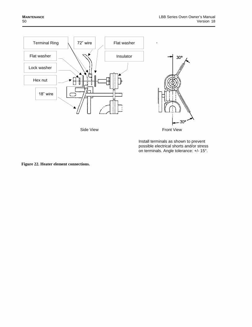
MAINTENANCE LBB Series Oven Owner’s Manual
50 Version 18
Flat washer Terminal Ring
Flat washer
Hex nut
Lock washer
Insulator
Install terminals as shown to prevent possible electrical shorts and/or stress on terminals. Angle tolerance: +/- 15°.
Front View Side View
72” wire
.
Figure 22. Heater element connections.
18” wire

LBB Series Oven Owner’s Manual MAINTENANCE
Version 18 51
6.5.5. Replace Fan Motor
Danger! Do not attempt any service on this oven before opening the main power disconnect switch or removing all power from the oven.
Tools needed:
One-quarter (1/4) inch socket set
5/32 inch Allen wrench
Screwdriver
T15, T20 and T30 Torx bit drivers
1. Disconnect power.
2. Remove shelves (Figure 21).
3. Remove left and right side ducts
a. Remove screws from each duct.
b. Remove duct from oven.
4. Remove heater cover (located on the top or bottom of the oven, depending on model).
a. Remove screws from the heater cover.
b. Remove heater cover from the oven.
5. Loosen setscrews (2) on fan wheel in middle of oven top. Access the fan wheel through the
heater opening or by disconnecting and removing the heater assembly. Refer to Section 6.5.4
for information on removing the heater unit.
6. Remove top cover to reveal fan motor (Figure 24).
Figure 23. Typical Heating Element (Inset connections see Figure 22) .
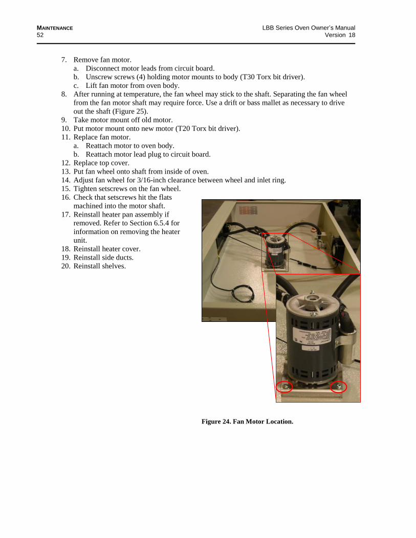
MAINTENANCE LBB Series Oven Owner’s Manual
52 Version 18
7. Remove fan motor.
a. Disconnect motor leads from circuit board.
b. Unscrew screws (4) holding motor mounts to body (T30 Torx bit driver).
c. Lift fan motor from oven body.
8. After running at temperature, the fan wheel may stick to the shaft. Separating the fan wheel
from the fan motor shaft may require force. Use a drift or bass mallet as necessary to drive
out the shaft (Figure 25).
9. Take motor mount off old motor.
10. Put motor mount onto new motor (T20 Torx bit driver).
11. Replace fan motor.
a. Reattach motor to oven body.
b. Reattach motor lead plug to circuit board.
12. Replace top cover.
13. Put fan wheel onto shaft from inside of oven.
14. Adjust fan wheel for 3/16-inch clearance between wheel and inlet ring.
15. Tighten setscrews on the fan wheel.
16. Check that setscrews hit the flats
machined into the motor shaft.
17. Reinstall heater pan assembly if
removed. Refer to Section 6.5.4 for
information on removing the heater
unit.
18. Reinstall heater cover.
19. Reinstall side ducts.
20. Reinstall shelves.
Figure 24. Fan Motor Location.

LBB Series Oven Owner’s Manual MAINTENANCE
Version 18 53
Fan wheel (spaced
0.25 from inside top)
Motor shaft
sleeve
Tinnerman clip
Motor mount
Motor
Torx screw
Torx screw
Figure 25. Separate fan wheel from fan motor shaft.

MAINTENANCE LBB Series Oven Owner’s Manual
54 Version 18
7. Troubleshooting
Table 7. Common Technical Issues and Remedies.
Technical Issue Probably Cause Suggested Remedy/Next Step
Failure to heat or only heats up to
30–50 °C
No power Check power source and/or oven and wall fuses.
Burned out heater(s) Replace element (see Warranty statement, Section 8.1).
Control Instrument malfunction
Check control parameters. Replace controller if OUT LED on controller does not turn on. See section 7.1 and 7.2
Loose wire connections
Disconnect power and check connections behind control panel.
Slow heat up
Improperly loaded workload
Reduce load or redistribute load in chamber.
Low line voltage Supply sufficient power and proper connections. Check for circuit overload.
1 or 2 heating elements burned out
Check heater amperage on the nameplate. Replace burned out element (see Warranty statement, Section 8.1).
Vent is wide open. Close vent.
Fan motor failure Replace fan motor.
Frequent heater element burnout
Harmful fumes generated by load
Increase vent opening or discontinue process.
Spillage or splattering of material on heater elements
Disconnect power and clean oven chamber and elements.
Overheating oven Check the Control and High Limit instruments.
Fan motor failure Replace fan motor.
Erratic temperature
Control instrument malfunction
Check control parameters before replacing the Control instrument.
Inaccurate temperature
Control instrument miscalibration
Check control parameters. Recalibrate Control instrument.
Excess surface or door temperature
Door seal deterioration Replace door seal.
Door closed into top or bottom latch only
See specific difficulty below for this problem.
Improper airflow
Fan motor failure Replace fan motor.
Unbalanced fan wheel Reposition fan wheel within 3/10” from top of housing. Replace fan wheel.
Excessive vibration
Dirty fan wheel Clean fan.
Unbalanced fan wheel Replace fan wheel.
Grinding noise Fan wheel has shifted or fallen.
Inspect the wheel. Reposition fan wheel within 0.25” from top of housing.
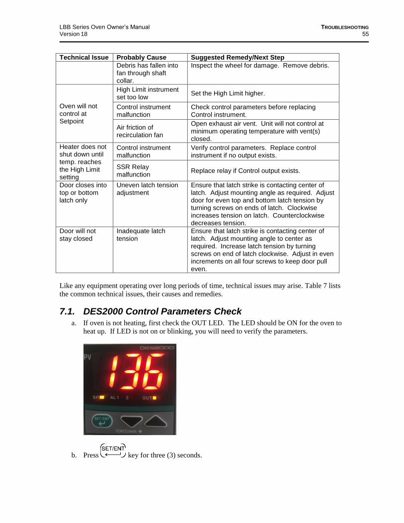
LBB Series Oven Owner’s Manual TROUBLESHOOTING
Version 18 55
Technical Issue Probably Cause Suggested Remedy/Next Step
Debris has fallen into fan through shaft collar.
Inspect the wheel for damage. Remove debris.
Oven will not control at Setpoint
High Limit instrument set too low
Set the High Limit higher.
Control instrument malfunction
Check control parameters before replacing Control instrument.
Air friction of recirculation fan
Open exhaust air vent. Unit will not control at minimum operating temperature with vent(s) closed.
Heater does not shut down until temp. reaches the High Limit setting
Control instrument malfunction
Verify control parameters. Replace control instrument if no output exists.
SSR Relay malfunction
Replace relay if Control output exists.
Door closes into top or bottom latch only
Uneven latch tension adjustment
Ensure that latch strike is contacting center of latch. Adjust mounting angle as required. Adjust door for even top and bottom latch tension by turning screws on ends of latch. Clockwise increases tension on latch. Counterclockwise decreases tension.
Door will not stay closed
Inadequate latch tension
Ensure that latch strike is contacting center of latch. Adjust mounting angle to center as required. Increase latch tension by turning screws on end of latch clockwise. Adjust in even increments on all four screws to keep door pull even.
Like any equipment operating over long periods of time, technical issues may arise. Table 7 lists
the common technical issues, their causes and remedies.
7.1. DES2000 Control Parameters Check a. If oven is not heating, first check the OUT LED. The LED should be ON for the oven to
heat up. If LED is not on or blinking, you will need to verify the parameters.
b. Press key for three (3) seconds.

TROUBLESHOOTING LBB Series Oven Owner’s Manual
56 Version 17.1
c. The CtL parameter should be displayed. Press one of the arrow keys once and PID
should be displayed, if it reads anything else, then it needs to be changed to PID.
d. If the value does not change when pressing the arrow key, then the parameters are locked.
e. Press and release the key several times until LOC is displayed. Press the down
arrow keys and change the parameter to 0 (zero).
f. Press the key several times to enter the value and return to LOC.
g. Press the key once so CtL is displayed again. Press one of the arrow keys until
PID is displayed.
h. Once the parameter PID is displayed, Press the key several times to go back to
CtL.
i. Press the key once to go to the next parameter. See Operating and Setup
Parameter Table listed below. The parameters are listed in order as they appear on the
control.
j. If the P is not displayed, the Control Mode (CtL) must be first set to PID.
k. Once you have verified each of the parameters, go to the LOC parameter and change the
value to 1 (one) to lock the parameters, but still allows the set point to be changed.
l. Press the key once to enter the value.
m. Press and hold the key for three (3) seconds until the temperature (PV) is
displayed.
n. If the PV reading is not the correct temperature, re-enter the parameter mode by Pressing
key for three (3) seconds.
o. Press and release the key several times until LOC is displayed.
p. If the parameter is not already 0 (zero), press the down arrow keys and change it to 0 and
then Press the key once.
q. Press the down arrow keys and change the parameter to -1 (minus one).
r. Press the key once so In is displayed. Press one of the arrow keys once and 5
should be displayed for Centigrade or 35 for Fahrenheit. To change from C to F or F to C,
please refer to the DES2000 controller manual.
s. Press key for three (3) seconds until the temperature (PV) is displayed.
t. If you changed the In parameter, you will need to go back to Step 1 to verify all the
parameters again.
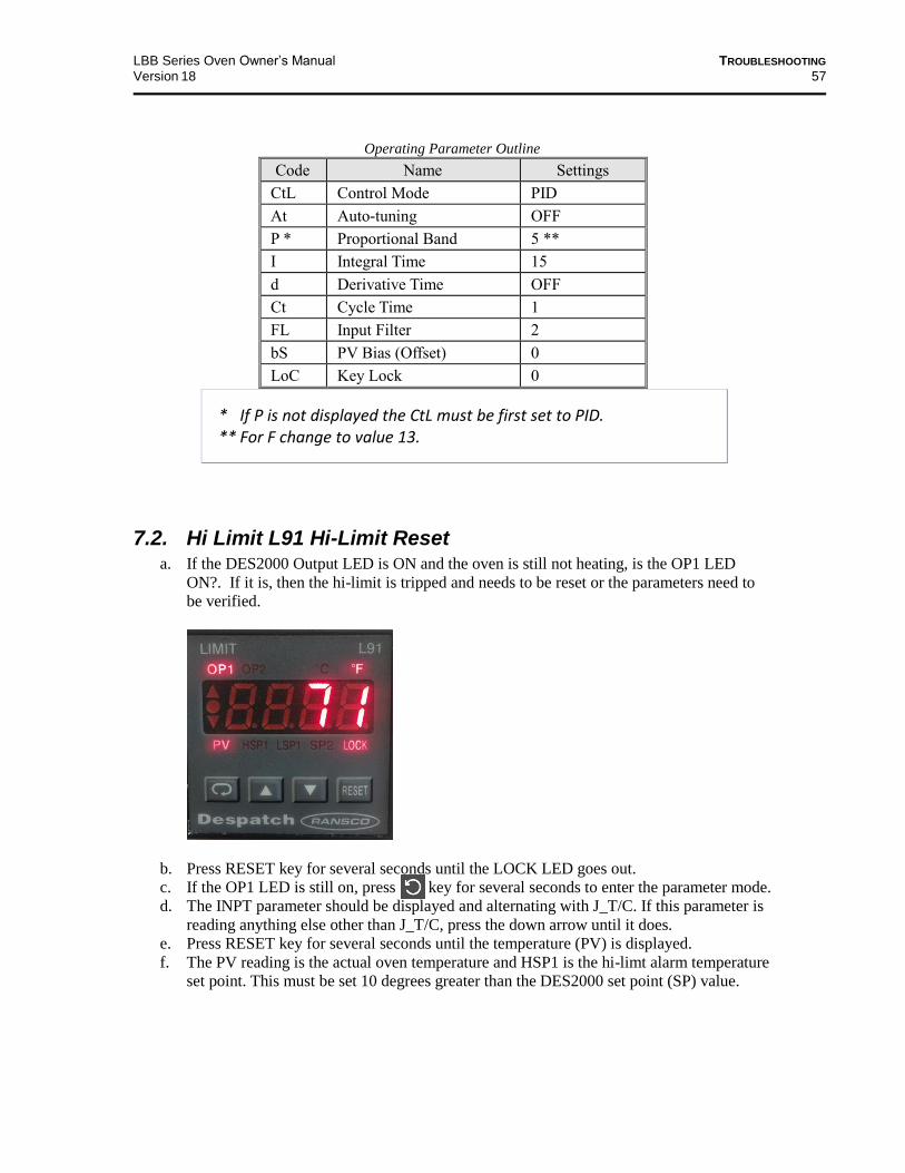
LBB Series Oven Owner’s Manual TROUBLESHOOTING
Version 18 57
Operating Parameter Outline
Code Name Settings
CtL Control Mode PID
At Auto-tuning OFF
P * Proportional Band 5 **
I Integral Time 15
d Derivative Time OFF
Ct Cycle Time 1
FL Input Filter 2
bS PV Bias (Offset) 0
LoC Key Lock 0
* If P is not displayed the CtL must be first set to PID. ** For F change to value 13.
7.2. Hi Limit L91 Hi-Limit Reset a. If the DES2000 Output LED is ON and the oven is still not heating, is the OP1 LED
ON?. If it is, then the hi-limit is tripped and needs to be reset or the parameters need to
be verified.
b. Press RESET key for several seconds until the LOCK LED goes out.
c. If the OP1 LED is still on, press key for several seconds to enter the parameter mode.
d. The INPT parameter should be displayed and alternating with J_T/C. If this parameter is
reading anything else other than J_T/C, press the down arrow until it does.
e. Press RESET key for several seconds until the temperature (PV) is displayed.
f. The PV reading is the actual oven temperature and HSP1 is the hi-limt alarm temperature
set point. This must be set 10 degrees greater than the DES2000 set point (SP) value.

APPENDICES LBB Series Oven Owner’s Manual
58 Version 18
8. Appendices
8.1. Standard Products Warranty
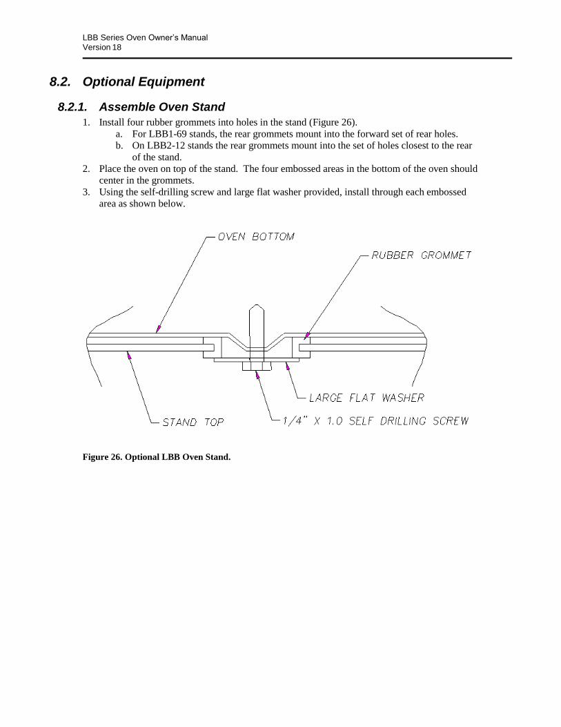
LBB Series Oven Owner’s Manual APPENDICES
Version 18 59
8.2. Optional Equipment
8.2.1. Assemble Oven Stand
1. Install four rubber grommets into holes in the stand (Figure 26).
a. For LBB1-69 stands, the rear grommets mount into the forward set of rear holes.
b. On LBB2-12 stands the rear grommets mount into the set of holes closest to the rear
of the stand.
2. Place the oven on top of the stand. The four embossed areas in the bottom of the oven should
center in the grommets.
3. Using the self-drilling screw and large flat washer provided, install through each embossed
area as shown below.
Figure 26. Optional LBB Oven Stand.
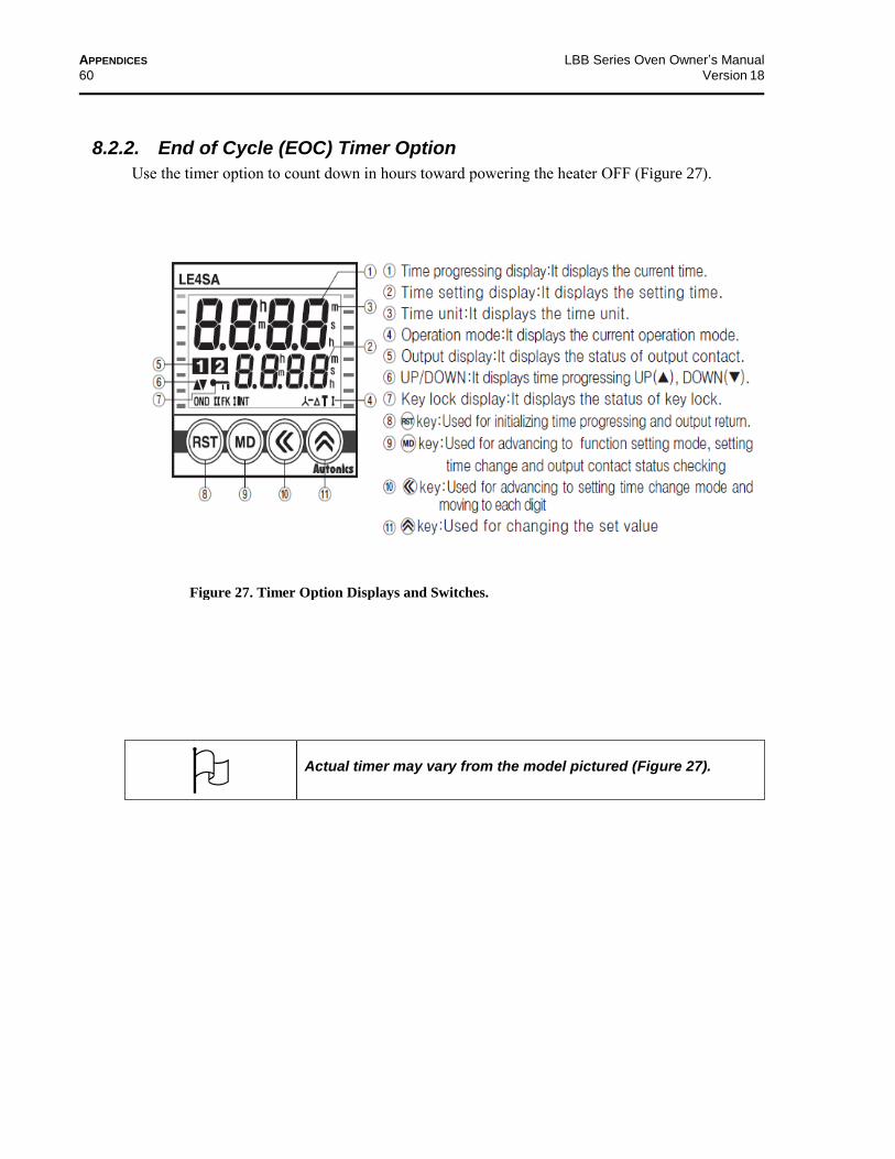
APPENDICES LBB Series Oven Owner’s Manual
60 Version 18
8.2.2. End of Cycle (EOC) Timer Option
Use the timer option to count down in hours toward powering the heater OFF (Figure 27).
Actual timer may vary from the model pictured (Figure 27).
Figure 27. Timer Option Displays and Switches.

LBB Series Oven Owner’s Manual APPENDICES
Version 18 61
8.2.3. Operating the Timer
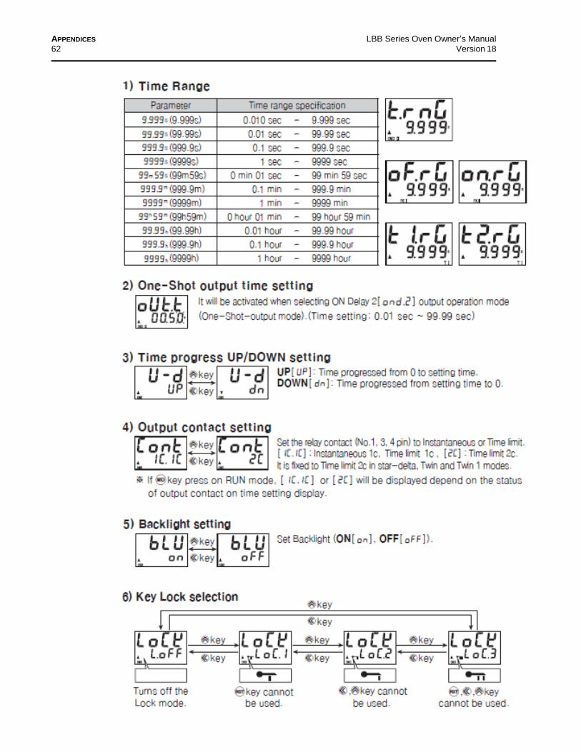
APPENDICES LBB Series Oven Owner’s Manual
62 Version 18

LBB Series Oven Owner’s Manual APPENDICES
Version 18 63
8.2.4. Parameter Default Settings
8.2.5. Timer Option with Audible and Visual Alarm
The Timer option sounds an alarm and turns on a light when the timer times out.
Clear the alarm condition by turning the heater switch OFF.
Reset the timer before turning heater switch ON.
Turning the timer switch off also clears the alarm condition, but the heater remains ON.
Each oven schematic (Section 8.4) shows the wiring for this option.
8.2.6. High Alarm Limit Option
The High Alarm Limit option sounds an alarm and turns on a light when a High Limit condition
occurs.
Silence the alarm horn by pressing the alarm silence switch. The light remains ON.
Clear the High Limit condition to clear the alarm. See Troubleshooting (Section 7) for
solutions to High Limit conditions.
Reset the High Limit instrument whenever it has tripped. Reset the High Limit Instrument by
allowing the oven chamber to cool slightly (or by setting the High Limit Instrument by
several degrees) and pushing .
Each oven schematic (Section 8.4) shows the wiring for this option.

APPENDICES LBB Series Oven Owner’s Manual
64 Version 18
8.3. Part Lists
Find many parts for Despatch ovens online at www.despatch.com/parts.aspx.
8.4. Mechanical Drawing
LBB1-23: Figure 28
LBB1-69: Figure 29
LBB2-12: Figure 30
LBB2-18: Figure 31
LBB2-27: Figure 32
8.5. Electrical Schematics The following pages provide electrical schematics for these LBB Series ovens:
LBB Standard (120 V): Figure 33
LBB Standard (240 V): Figure 34Figure 34
LBB Opt P-3 (120 V): Figure 35Figure 35
LBB Opt P-3 (240 V): Figure 36Figure 36
Note that each schematic also includes wiring for the Timer (8.2.2) and High Limit Alarm (8.2.6)
options.
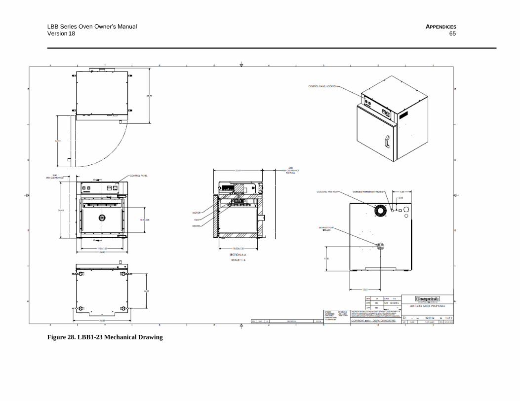
LBB Series Oven Owner’s Manual APPENDICES
Version 18 65
Figure 28. LBB1-23 Mechanical Drawing
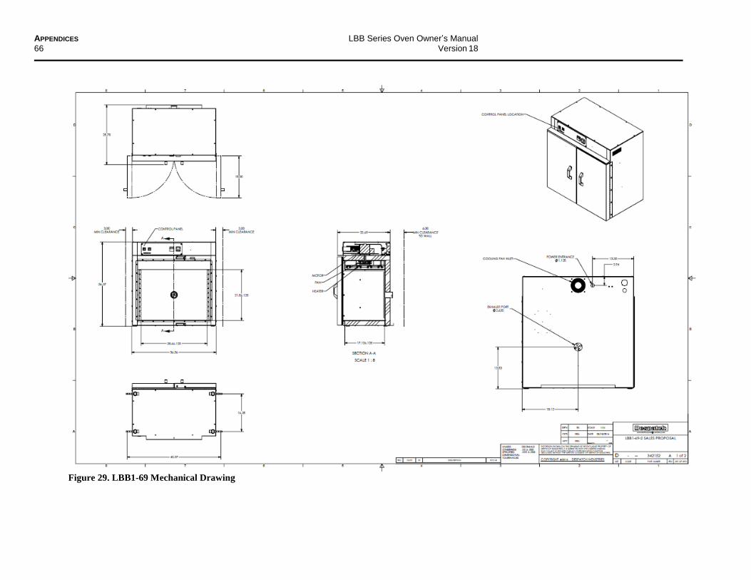
APPENDICES LBB Series Oven Owner’s Manual
66 Version 18
Figure 29. LBB1-69 Mechanical Drawing
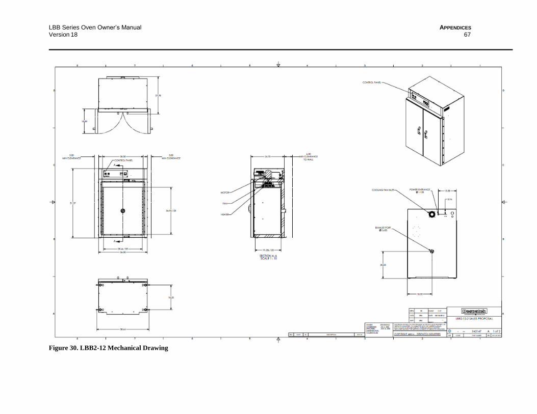
LBB Series Oven Owner’s Manual APPENDICES
Version 18 67
Figure 30. LBB2-12 Mechanical Drawing
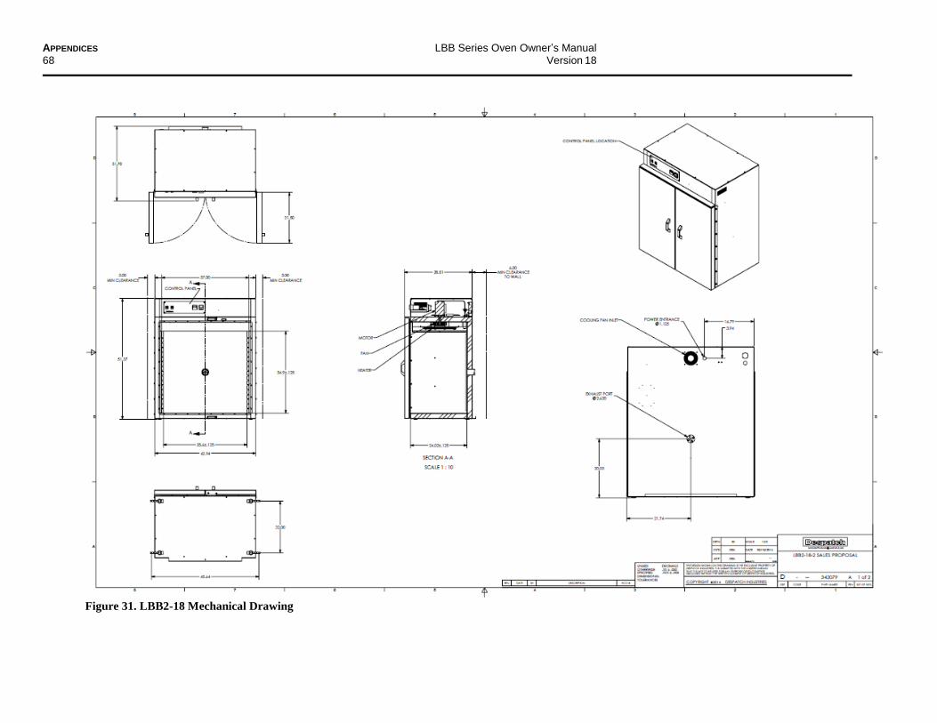
APPENDICES LBB Series Oven Owner’s Manual
68 Version 18
Figure 31. LBB2-18 Mechanical Drawing
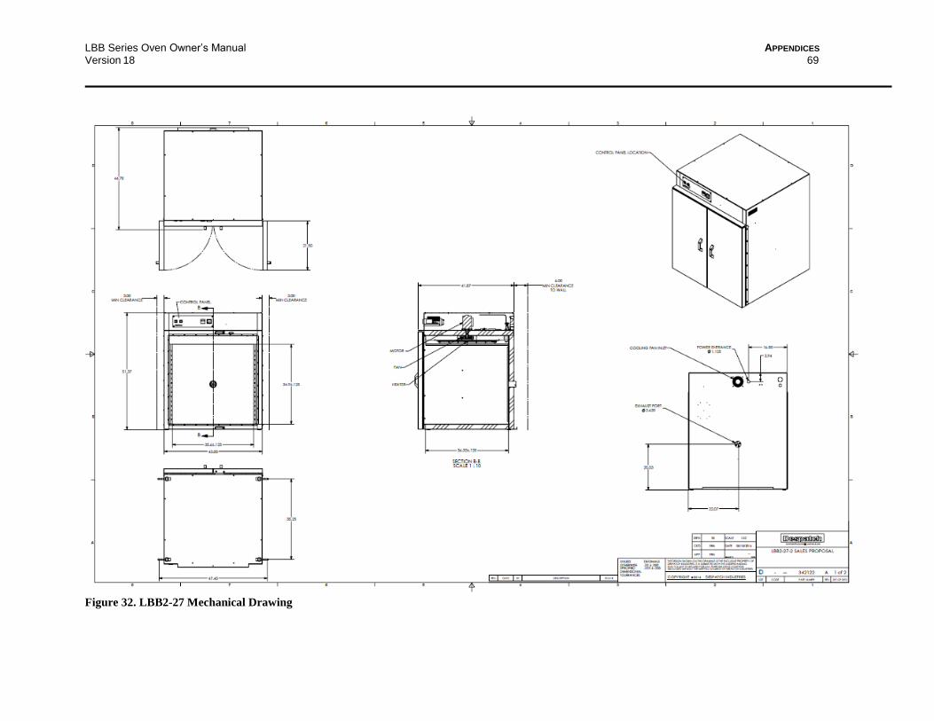
LBB Series Oven Owner’s Manual APPENDICES
Version 18 69
Figure 32. LBB2-27 Mechanical Drawing

APPENDICES LBB Series Oven Owner’s Manual
70 Version 18
Figure 33. LBB Standard (120 V) Schematic.
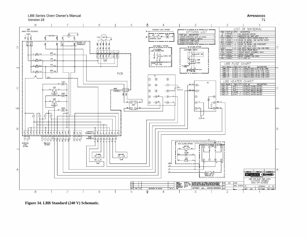
LBB Series Oven Owner’s Manual APPENDICES
Version 18 71
Figure 34. LBB Standard (240 V) Schematic.
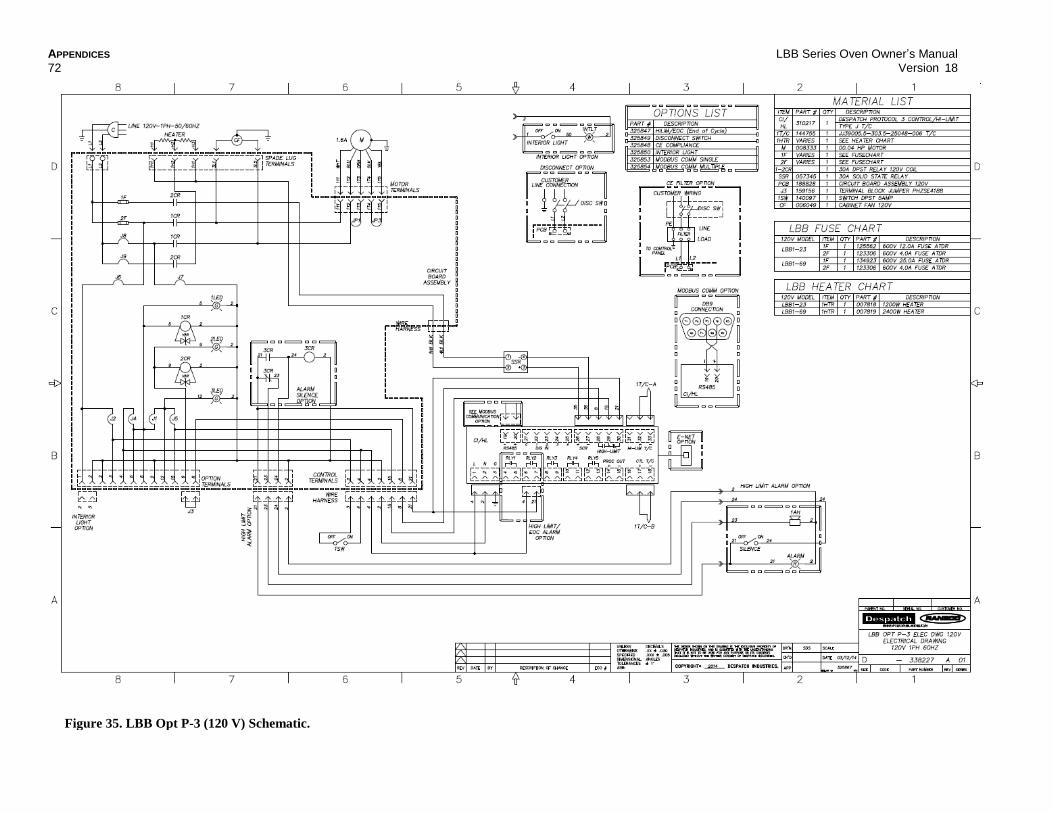
APPENDICES LBB Series Oven Owner’s Manual
72 Version 18
Figure 35. LBB Opt P-3 (120 V) Schematic.

LBB Series Oven Owner’s Manual APPENDICES
Version 18 73
Figure 36. LBB Opt P-3 (240 V) Schematic.
LBB Series Oven Owner’s Manual 74 Version 18
3rdDraft—