Layered shape synthesis: automatic generation of control ...dcor/articles/2009/Layered-Shape.pdf ·...
10
ACM Reference Format Rosenberger, A., Cohen-Or, D., Lischinski, D. 2009. Layered Shape Synthesis: Automatic Generation of Control Maps for Non-Stationary Textures. ACM Trans. Graph. 28, 5, Article 107 (December 2009), 9 pages. DOI = 10.1145/1618452.1618453 http://doi.acm.org/10.1145/1618452.1618453. Copyright Notice Permission to make digital or hard copies of part or all of this work for personal or classroom use is granted without fee provided that copies are not made or distributed for profit or direct commercial advantage and that copies show this notice on the first page or initial screen of a display along with the full citation. Copyrights for components of this work owned by others than ACM must be honored. Abstracting with credit is permitted. To copy otherwise, to republish, to post on servers, to redistribute to lists, or to use any component of this work in other works requires prior specific permission and/or a fee. Permissions may be requested from Publications Dept., ACM, Inc., 2 Penn Plaza, Suite 701, New York, NY 10121-0701, fax +1 (212) 869-0481, or [email protected]. © 2009 ACM 0730-0301/2009/05-ART107 $10.00 DOI 10.1145/1618452.1618453 http://doi.acm.org/10.1145/1618452.1618453 Layered Shape Synthesis: Automatic Generation of Control Maps for Non-Stationary Textures Amir Rosenberger Tel Aviv University Daniel Cohen-Or Tel Aviv University Dani Lischinski The Hebrew University Figure 1: An inhomogeneous texture, exhibiting a non-uniform mixture of peeling paint, bare metal, and rust. From left to right: input texture exemplar, control map extracted from the exemplar, a larger control map synthesized by our approach, and the resulting new texture. Abstract Many inhomogeneous real-world textures are non-stationary and exhibit various large scale patterns that are easily perceived by a human observer. Such textures violate the assumptions underly- ing most state-of-the-art example-based synthesis methods. Con- sequently, they cannot be properly reproduced by these methods, unless a suitable control map is provided to guide the synthesis process. Such control maps are typically either user specified or generated by a simulation. In this paper, we present an alternative: a method for automatic example-based generation of control maps, geared at synthesis of natural, highly inhomogeneous textures, such as those resulting from natural aging or weathering processes. Our method is based on the observation that an appropriate control map for many of these textures may be modeled as a superposition of several layers, where the visible parts of each layer are occupied by a more homogeneous texture. Thus, given a decomposition of a texture exemplar into a small number of such layers, we employ a novel example-based shape synthesis algorithm to automatically generate a new set of layers. Our shape synthesis algorithm is de- signed to preserve both local and global characteristics of the exem- plar’s layer map. This process results in a new control map, which then may be used to guide the subsequent texture synthesis process. Keywords: control maps, example-based texture synthesis, non- stationary textures, shape synthesis 1 Introduction Computer generated imagery relies heavily on textures to achieve realism. One easy way to acquire realistic textures is by scanning or taking photographs of surfaces and materials that surround us in the real world. Therefore, a large number of methods have been pro- posed for synthesizing textures from examples, in the last decade [Wei et al. 2009]. Many of these methods are able to produce im- pressive results when applied to homogeneous textures that may be described by stationary Markov random field (MRF) models. Yet many real world textures are highly inhomogeneous, and are not modeled well by a stationary stochastic process. Consider, for example, the rusty metal surface shown on the left in Figure 1. The texture on this surface is clearly non-stationary, and it may be seen as a highly non-uniform mixture, or superposition, of several different textures: peeling paint, bare metal, and rust. While each of these three textures is roughly homogeneous, the texture as a whole is not. This is a typical situation for many real world surfaces, whose texture often results from natural processes, such as weathering, corrosion, color cracking and peeling, growth of moss, etc. [Dorsey and Hanrahan 1996; Dorsey et al. 1999; Bosch et al. 2004; Desbenoit et al. 2004; Dorsey et al. 2008]. A common remedy to cope with such textures is to guide the syn- thesis process by a control map that encodes the large scale varia- tions and the non-local features of the desired output texture (e.g., [Ashikhmin 2001; Hertzmann et al. 2001; Zhang et al. 2003; Wang et al. 2006; Wei et al. 2008]). However, such control maps are typ- ically either user-specified or produced by a custom tailored simu- lation (e.g., biological or physically-based). In this work we propose a new method for automatically generat- ing control maps from examples, geared at natural textures such as the one in Figure 1. As observed above, such textures often look like a superposition of several layers, where each visible regions of each layer are occupied by a more homogeneous texture. The shape of the texture-occupied regions in each layer is far from arbitrary. Rather, it is the consequence of the specific natural process that pro- duced this texture, as well as the shape of the layer underneath. Nei- ther global statistics, nor small neighborhoods are capable of faith- fully capturing such higher level structures. Such appearances may be generated by specialized shaders or by physically-based simu- lations. However, we are not aware of any general fully automatic way for generating such a shader from a specific example. Our approach begins by decomposing the input exemplar into a number of layers, which we order bottom to top. A novel example- based shape synthesis algorithm is then used to generate a new set ACM Transactions on Graphics, Vol. 28, No. 5, Article 107, Publication date: December 2009.
Transcript of Layered shape synthesis: automatic generation of control ...dcor/articles/2009/Layered-Shape.pdf ·...
ACM Reference FormatRosenberger, A., Cohen-Or, D., Lischinski, D. 2009. Layered Shape Synthesis: Automatic Generation of Control Maps for Non-Stationary Textures. ACM Trans. Graph. 28, 5, Article 107 (December 2009), 9 pages. DOI = 10.1145/1618452.1618453 http://doi.acm.org/10.1145/1618452.1618453.
Copyright NoticePermission to make digital or hard copies of part or all of this work for personal or classroom use is granted without fee provided that copies are not made or distributed for profi t or direct commercial advantage and that copies show this notice on the fi rst page or initial screen of a display along with the full citation. Copyrights for components of this work owned by others than ACM must be honored. Abstracting with credit is permitted. To copy otherwise, to republish, to post on servers, to redistribute to lists, or to use any component of this work in other works requires prior specifi c permission and/or a fee. Permissions may be requested from Publications Dept., ACM, Inc., 2 Penn Plaza, Suite 701, New York, NY 10121-0701, fax +1 (212) 869-0481, or [email protected].© 2009 ACM 0730-0301/2009/05-ART107 $10.00 DOI 10.1145/1618452.1618453 http://doi.acm.org/10.1145/1618452.1618453
Layered Shape Synthesis: Automatic Generation of Control Maps for Non-Stationary Textures
Amir RosenbergerTel Aviv University
Daniel Cohen-OrTel Aviv University
Dani LischinskiThe Hebrew University
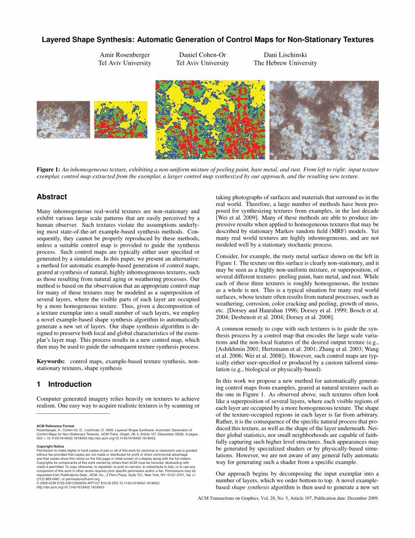
Figure 1: An inhomogeneous texture, exhibiting a non-uniform mixture of peeling paint, bare metal, and rust. From left to right: input textureexemplar, control map extracted from the exemplar, a larger control map synthesized by our approach, and the resulting new texture.
Abstract
Many inhomogeneous real-world textures are non-stationary andexhibit various large scale patterns that are easily perceived by ahuman observer. Such textures violate the assumptions underly-ing most state-of-the-art example-based synthesis methods. Con-sequently, they cannot be properly reproduced by these methods,unless a suitable control map is provided to guide the synthesisprocess. Such control maps are typically either user specified orgenerated by a simulation. In this paper, we present an alternative:a method for automatic example-based generation of control maps,geared at synthesis of natural, highly inhomogeneous textures, suchas those resulting from natural aging or weathering processes. Ourmethod is based on the observation that an appropriate control mapfor many of these textures may be modeled as a superposition ofseveral layers, where the visible parts of each layer are occupiedby a more homogeneous texture. Thus, given a decomposition ofa texture exemplar into a small number of such layers, we employa novel example-based shape synthesis algorithm to automaticallygenerate a new set of layers. Our shape synthesis algorithm is de-signed to preserve both local and global characteristics of the exem-plar’s layer map. This process results in a new control map, whichthen may be used to guide the subsequent texture synthesis process.
Keywords: control maps, example-based texture synthesis, non-stationary textures, shape synthesis
1 Introduction
Computer generated imagery relies heavily on textures to achieverealism. One easy way to acquire realistic textures is by scanning or
taking photographs of surfaces and materials that surround us in thereal world. Therefore, a large number of methods have been pro-posed for synthesizing textures from examples, in the last decade[Wei et al. 2009]. Many of these methods are able to produce im-pressive results when applied to homogeneous textures that may bedescribed by stationary Markov random field (MRF) models. Yetmany real world textures are highly inhomogeneous, and are notmodeled well by a stationary stochastic process.
Consider, for example, the rusty metal surface shown on the left inFigure 1. The texture on this surface is clearly non-stationary, and itmay be seen as a highly non-uniform mixture, or superposition, ofseveral different textures: peeling paint, bare metal, and rust. Whileeach of these three textures is roughly homogeneous, the textureas a whole is not. This is a typical situation for many real worldsurfaces, whose texture often results from natural processes, such asweathering, corrosion, color cracking and peeling, growth of moss,etc. [Dorsey and Hanrahan 1996; Dorsey et al. 1999; Bosch et al.2004; Desbenoit et al. 2004; Dorsey et al. 2008].
A common remedy to cope with such textures is to guide the syn-thesis process by a control map that encodes the large scale varia-tions and the non-local features of the desired output texture (e.g.,[Ashikhmin 2001; Hertzmann et al. 2001; Zhang et al. 2003; Wanget al. 2006; Wei et al. 2008]). However, such control maps are typ-ically either user-specified or produced by a custom tailored simu-lation (e.g., biological or physically-based).
In this work we propose a new method for automatically generat-ing control maps from examples, geared at natural textures such asthe one in Figure 1. As observed above, such textures often looklike a superposition of several layers, where each visible regions ofeach layer are occupied by a more homogeneous texture. The shapeof the texture-occupied regions in each layer is far from arbitrary.Rather, it is the consequence of the specific natural process that pro-duced this texture, as well as the shape of the layer underneath. Nei-ther global statistics, nor small neighborhoods are capable of faith-fully capturing such higher level structures. Such appearances maybe generated by specialized shaders or by physically-based simu-lations. However, we are not aware of any general fully automaticway for generating such a shader from a specific example.
Our approach begins by decomposing the input exemplar into anumber of layers, which we order bottom to top. A novel example-based shape synthesis algorithm is then used to generate a new set
ACM Transactions on Graphics, Vol. 28, No. 5, Article 107, Publication date: December 2009.
of layers, whose local and global characteristics visually resemblethose of the exemplar’s layers. This algorithm makes use of a bidi-rectional measure of similarity between the shapes of the layers,which is based on the shapes’ boundaries. Starting from some ini-tial output shape, we iteratively optimize the shape with respect tothis similarity measure. Once the new layers are available, a texturetransfer process based on “texture-by-numbers” [Hertzmann et al.2001] is invoked, resulting in the final output texture, such as theresult shown in Figure 1.
In summary, the main novelty in our approach lies in example-basedsynthesis of a suitable control map, rather than working directly onthe texture, or on some associated appearance space [Lefebvre andHoppe 2006]. To our knowledge, such an approach has not beenexplored before.
2 Related Work
Example-based texture synthesis has enjoyed considerable researchattention in recent years. Most of the relevant previous meth-ods may be roughly classified to parametric methods [Heegerand Bergen 1995], and non-parametric methods, which includepixel-based methods [Efros and Leung 1999; Wei and Levoy2000], patch-based methods [Efros and Freeman 2001; Kwatraet al. 2003], optimization-based methods [Kwatra et al. 2005], andappearance-space texture synthesis [Lefebvre and Hoppe 2006].Parametric methods attempt to construct a parametric model of thetexture based on the input sample, which has proven to be a chal-lenging task, and are mostly successful with structureless station-ary textures. Non-parametric methods have demonstrated the abil-ity to handle a wider variety of textures, by growing the textureone pixel/patch at a time. Optimization-based methods evolve thetexture as a whole, further improving the quality of the results andmaking the synthesis more controllable. We refer the reader to [Weiet al. 2009] for a more comprehensive overview of example-basedtexture synthesis.
While non-parametric methods are typically able to reproducesmall scale structure, they have a difficulty coping with highly in-homogeneous textures, since such textures cannot be modeled bya stationary Markov Random Field (MRF) model, which providesthe theoretical basis for most of these methods. In order to handlesuch textures and control large scale structure, Ashikhmin [2001]proposed to guide the synthesis process by a user-provided targetimage, which specifies the local average colors across the targettexture. Texture-by-Numbers [Hertzmann et al. 2001] extends thisidea further by augmenting the input exemplar with a label map,where regions with distinct texture are distinguished by differentlabels. A suitable label map may be painted manually by the user,or created automatically using unsupervised image segmentation.To synthesize a new image, a target label map is provided, whichindicates how the different textures should be arranged in the re-sulting image. However, that work addressed neither the issue ofautomatically generating a label map for natural inhomogeneoustextures, nor the automatic synthesis of the target label map, as wedo in our work.
Many other works since made use of control maps when synthesiz-ing non-stationary textures, for example [Zhang et al. 2003; Wanget al. 2006; Gu et al. 2006; Lu et al. 2007; Wei et al. 2008]. How-ever, in all of these works the control map for the target texture iseither provided by the user, or derived from a specific model of tex-ture formation across a 3D surface (e.g., [Lu et al. 2007]), and weare not aware of any previous attempts of example-based controlmap generation.
Our shape synthesis approach is related to texture optimizationtechniques [Wexler et al. 2004; Kwatra et al. 2005], which synthe-
size textures by minimizing a texture energy function. This func-tion consists of a sum of local terms measuring how close eachsynthesized texture patch is to an exemplar patch. However, thisformulation does not account for the possibility that there may bemany other patches in the exemplar that are not represented at allin the synthesized result. While this may be adequate for homo-geneous textures, where most patches are similar to each other, thequality of the results for inhomogeneous textures is often compro-mised. While it is possible to inject some global statistics into theoptimization [Kopf et al. 2007], the resulting process still fails tocapture the large scale appearance of highly inhomogeneous natu-ral textures that are the target of this work. In contrast, we performshape synthesis with a bidirectional similarity measure (inspired bySimakov et al. [2008] and Wei et al. [Wei et al. 2008]), and demon-strate more faithful reproduction of appearance in the comparisonswe present in Section 4.
Appearance-space texture synthesis [Lefebvre and Hoppe 2006] isanother optimization method that operates in a feature space, ratherthan using the values of pixels or small patches directly. A pointcorresponding to a pixel in a more general feature space may en-code more information, allowing structure to be reproduced better.The layer map that we associate with the input exemplar in ourapproach could be viewed as a feature space custom-tailored forsynthesis of layered inhomogeneous textures.
A variety of methods generate textures of weathered surfaces byassuming and simulating a physical model [Dorsey and Hanrahan1996; Dorsey et al. 1999; Merillou et al. 2001; Bosch et al. 2004;Desbenoit et al. 2004; Dorsey et al. 2008]. While such methodshave produced some highly realistic results, they are not geared to-wards matching a particular appearance given by an example. Also,controlling the results of the synthesis typically involves specify-ing a large number of parameters, which are not always intuitive.In contrast, our approach is example-based, rather than physically-based.
Our approach synthesizes the boundaries of the layer shapes by ex-ample. Thus, it is related to the Curve Analogies work of Hertz-mann et al. [2002], where a similar framework was applied toreproduce the style of curved shapes. However, our work uses adifferent similarity measure and operates on a discrete patch-basedrepresentation of a shape’s boundary, rather than a vector-based rep-resentation. Also related is the work of Baht et al. [2004], whichuses binary voxel grids in order to synthesize geometric details onvolume surfaces. These voxel grids are similar to the binary neigh-borhoods that we use to optimize the shape boundaries. However,their goal is to add smaller-scale detail to an existing global shape,while we focus on synthesizing the entire shape from scratch.
3 Layered Shape Synthesis
This work deals with example-based generation of control mapsrepresented as layer maps. A layer map is an image where differ-ent pixel values indicate to different layers. Let v1 < v2 < .. . < vKbe the values of layer map pixels, sorted in ascending order. Then,a layer Li is defined as the set of all pixels whose value is greaterthan or equal to vi. Note that a pixel with value v j actually belongsto all layers L1, . . . ,L j. One can think of the layers as stacked ontop of each other, with layers higher in the stack partially “conceal-ing” lower layers. Each layer has an associated foreground shapeSi, which we encode as a binary image of the same dimensionsas the layer map. Note that the shape Si+1 is always contained inSi. As may be seen in Figures 1 and 6, the boundaries of thesenested shapes are highly correlated, but not aligned. In the figuresin this paper, we display values corresponding to different layersusing unique colors.
107:2 • A. Rosenberger et al.
ACM Transactions on Graphics, Vol. 28, No. 5, Article 107, Publication date: December 2009.
a b c d e
a b c d e
a 0.0 1.3 3.0 5.3 6.0b 0.0 2.7 5.0 5.4c 0.0 5.0 5.3d 0.0 4.6e 0.0
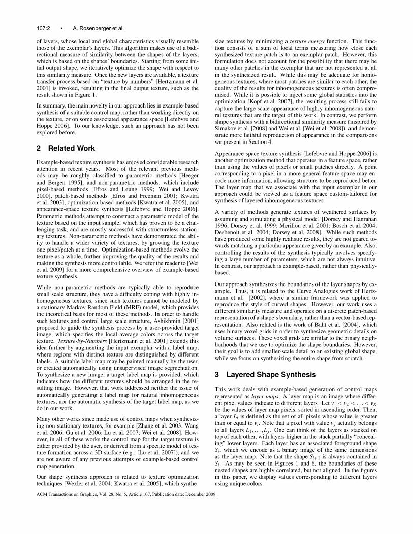
Figure 2: Similarity measure between pairs of five different shapes.
Given a set of such shapes, our goal is to synthesize a new set ofshapes, while maintaining both global and local similarity to theoriginal ones. For this purpose, it is important that each shape oc-cupies the same relative amount of pixels in the synthesized mapas it did in the exemplar, and that the boundaries of the synthe-sized shapes locally resemble those in the exemplar. We found thatrepresenting the shape by means of its boundary curve fails to cap-ture all of the relevant information. Such a representation cannotpredict the spatial relationship between disconnected componentsof the shape, and does not prevent self-intersections. Instead, werepresent a binary shape by a collection of patches centered on theshape’s boundary pixels (at multiple resolutions) in order to cap-tures the necessary shape properties.
Our shape synthesis approach employs optimization similarly to[Wexler et al. 2004; Kwatra et al. 2005], where the synthesized re-sult is iteratively optimized with respect to some measure of its sim-ilarity with the exemplar. We begin by deriving a suitable bidirec-tional shape similarity measure, similarly to Simakov et al. [2008]and Wei et al. [2008]. Next, we describe a novel greedy optimiza-tion scheme that iteratively modifies an initial shape, so as to in-crease its similarity to a given exemplar shape. Finally, we dis-cuss how this mechanism is used to create an entire new layer map,which is a sequence of nested shapes, from the layer map producedin the layer decomposition phase described in the previous section.
3.1 Shape similarity measure
Let B1 and B2 be the sets of boundary pixels of shapes S1 andS2, respectfully. A boundary pixel is a pixel inside a shape withat least one of its 4-neighbors outside the shape. Let x1 ∈ B1and x2 ∈ B2 be two boundary pixels, and let Nθ(x1) and Nη(x2)be the neighborhoods centered around them and rotated by θ,η ∈{0◦,90◦,180◦,270◦}. We refer to such neighborhoods as boundarypatches. We define the similarity, D, between two boundary pixelsas the L2 distance between their neighborhoods (rotated such thatthe distance is minimized). Formally,
D(x1,x2) = minη
∥∥N0(x1)−Nη(x2)∥∥
2 (1)
Since we deal with binary images, the L2 norm above is simplythe number of different pixels between two patches. Next, we de-fine the local similarity between a boundary pixel x1 ∈ B1 and theboundary of (another) shape S2 as the similarity between x1 and thepixel most similar to it on the boundary B2:
D(x1,S2) = minx2∈B2
D(x1,x2). (2)
Note that this similarity measure is not symmetric. While it ensuresthat every boundary patch of S1 is similar to a boundary patch in S2,
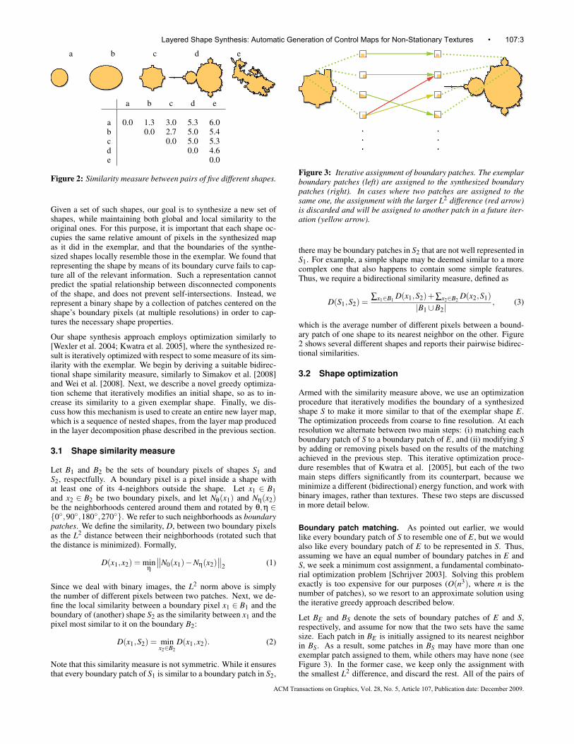
Figure 3: Iterative assignment of boundary patches. The exemplarboundary patches (left) are assigned to the synthesized boundarypatches (right). In cases where two patches are assigned to thesame one, the assignment with the larger L2 difference (red arrow)is discarded and will be assigned to another patch in a future iter-ation (yellow arrow).
there may be boundary patches in S2 that are not well represented inS1. For example, a simple shape may be deemed similar to a morecomplex one that also happens to contain some simple features.Thus, we require a bidirectional similarity measure, defined as
D(S1,S2) =∑x1∈B1 D(x1,S2)+∑x2∈B2 D(x2,S1)
|B1∪B2|, (3)
which is the average number of different pixels between a bound-ary patch of one shape to its nearest neighbor on the other. Figure2 shows several different shapes and reports their pairwise bidirec-tional similarities.
3.2 Shape optimization
Armed with the similarity measure above, we use an optimizationprocedure that iteratively modifies the boundary of a synthesizedshape S to make it more similar to that of the exemplar shape E.The optimization proceeds from coarse to fine resolution. At eachresolution we alternate between two main steps: (i) matching eachboundary patch of S to a boundary patch of E, and (ii) modifying Sby adding or removing pixels based on the results of the matchingachieved in the previous step. This iterative optimization proce-dure resembles that of Kwatra et al. [2005], but each of the twomain steps differs significantly from its counterpart, because weminimize a different (bidirectional) energy function, and work withbinary images, rather than textures. These two steps are discussedin more detail below.
Boundary patch matching. As pointed out earlier, we wouldlike every boundary patch of S to resemble one of E, but we wouldalso like every boundary patch of E to be represented in S. Thus,assuming we have an equal number of boundary patches in E andS, we seek a minimum cost assignment, a fundamental combinato-rial optimization problem [Schrijver 2003]. Solving this problemexactly is too expensive for our purposes (O(n3), where n is thenumber of patches), so we resort to an approximate solution usingthe iterative greedy approach described below.
Let BE and BS denote the sets of boundary patches of E and S,respectively, and assume for now that the two sets have the samesize. Each patch in BE is initially assigned to its nearest neighborin BS. As a result, some patches in BS may have more than oneexemplar patch assigned to them, while others may have none (seeFigure 3). In the former case, we keep only the assignment withthe smallest L2 difference, and discard the rest. All of the pairs of
Layered Shape Synthesis: Automatic Generation of Control Maps for Non-Stationary Textures • 107:3
ACM Transactions on Graphics, Vol. 28, No. 5, Article 107, Publication date: December 2009.
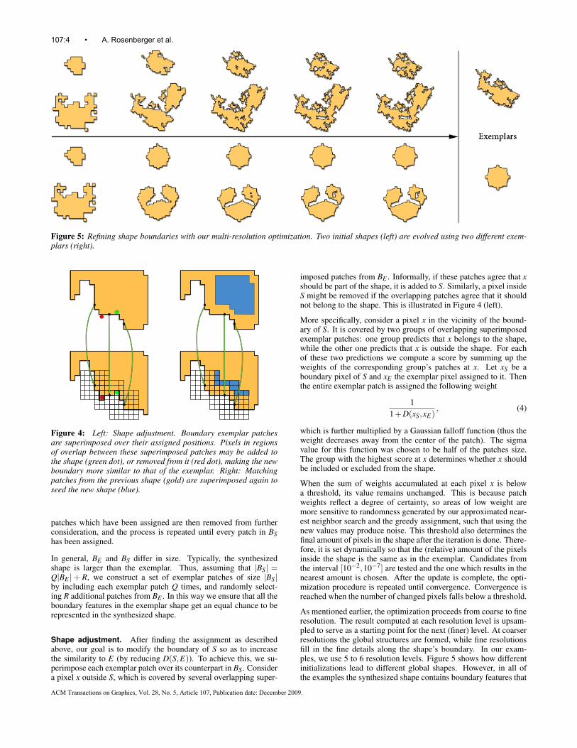
Figure 5: Refining shape boundaries with our multi-resolution optimization. Two initial shapes (left) are evolved using two different exem-plars (right).
Figure 4: Left: Shape adjustment. Boundary exemplar patchesare superimposed over their assigned positions. Pixels in regionsof overlap between these superimposed patches may be added tothe shape (green dot), or removed from it (red dot), making the newboundary more similar to that of the exemplar. Right: Matchingpatches from the previous shape (gold) are superimposed again toseed the new shape (blue).
patches which have been assigned are then removed from furtherconsideration, and the process is repeated until every patch in BShas been assigned.
In general, BE and BS differ in size. Typically, the synthesizedshape is larger than the exemplar. Thus, assuming that |BS| =Q|BE |+ R, we construct a set of exemplar patches of size |BS|by including each exemplar patch Q times, and randomly select-ing R additional patches from BE . In this way we ensure that all theboundary features in the exemplar shape get an equal chance to berepresented in the synthesized shape.
Shape adjustment. After finding the assignment as describedabove, our goal is to modify the boundary of S so as to increasethe similarity to E (by reducing D(S,E)). To achieve this, we su-perimpose each exemplar patch over its counterpart in BS. Considera pixel x outside S, which is covered by several overlapping super-
imposed patches from BE . Informally, if these patches agree that xshould be part of the shape, it is added to S. Similarly, a pixel insideS might be removed if the overlapping patches agree that it shouldnot belong to the shape. This is illustrated in Figure 4 (left).
More specifically, consider a pixel x in the vicinity of the bound-ary of S. It is covered by two groups of overlapping superimposedexemplar patches: one group predicts that x belongs to the shape,while the other one predicts that x is outside the shape. For eachof these two predictions we compute a score by summing up theweights of the corresponding group’s patches at x. Let xS be aboundary pixel of S and xE the exemplar pixel assigned to it. Thenthe entire exemplar patch is assigned the following weight
11+D(xS,xE)
, (4)
which is further multiplied by a Gaussian falloff function (thus theweight decreases away from the center of the patch). The sigmavalue for this function was chosen to be half of the patches size.The group with the highest score at x determines whether x shouldbe included or excluded from the shape.
When the sum of weights accumulated at each pixel x is belowa threshold, its value remains unchanged. This is because patchweights reflect a degree of certainty, so areas of low weight aremore sensitive to randomness generated by our approximated near-est neighbor search and the greedy assignment, such that using thenew values may produce noise. This threshold also determines thefinal amount of pixels in the shape after the iteration is done. There-fore, it is set dynamically so that the (relative) amount of the pixelsinside the shape is the same as in the exemplar. Candidates fromthe interval [10−2,10−7] are tested and the one which results in thenearest amount is chosen. After the update is complete, the opti-mization procedure is repeated until convergence. Convergence isreached when the number of changed pixels falls below a threshold.
As mentioned earlier, the optimization proceeds from coarse to fineresolution. The result computed at each resolution level is upsam-pled to serve as a starting point for the next (finer) level. At coarserresolutions the global structures are formed, while fine resolutionsfill in the fine details along the shape’s boundary. In our exam-ples, we use 5 to 6 resolution levels. Figure 5 shows how differentinitializations lead to different global shapes. However, in all ofthe examples the synthesized shape contains boundary features that
107:4 • A. Rosenberger et al.
ACM Transactions on Graphics, Vol. 28, No. 5, Article 107, Publication date: December 2009.
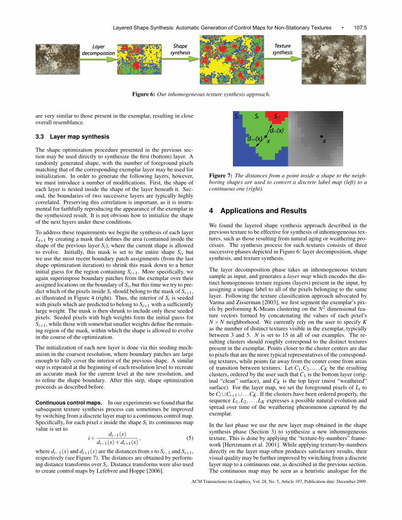
Figure 6: Our inhomogeneous texture synthesis approach.
are very similar to those present in the exemplar, resulting in closeoverall resemblance.
3.3 Layer map synthesis
The shape optimization procedure presented in the previous sec-tion may be used directly to synthesize the first (bottom) layer. Arandomly generated shape, with the number of foreground pixelsmatching that of the corresponding exemplar layer may be used forinitialization. In order to generate the following layers, however,we must introduce a number of modifications. First, the shape ofeach layer is nested inside the shape of the layer beneath it. Sec-ond, the boundaries of two successive layers are typically highlycorrelated. Preserving this correlation is important, as it is instru-mental for faithfully reproducing the appearance of the exemplar inthe synthesized result. It is not obvious how to initialize the shapeof the next layers under these conditions.
To address these requirements we begin the synthesis of each layerLi+1 by creating a mask that defines the area (contained inside theshape of the previous layer Si), where the current shape is allowedto evolve. Initially, this mask is set to the entire shape Si, butwe use the most recent boundary patch assignments (from the lastshape optimization iteration) to shrink this mask down to a betterinitial guess for the region containing Si+1. More specifically, weagain superimpose boundary patches from the exemplar over theirassigned locations on the boundary of Si, but this time we try to pre-dict which of the pixels inside Si should belong to the mask of Si+1,as illustrated in Figure 4 (right). Thus, the interior of Si is seededwith pixels which are predicted to belong to Si+1 with a sufficientlylarge weight. The mask is then shrunk to include only these seededpixels. Seeded pixels with high weights form the initial guess forSi+1, while those with somewhat smaller weights define the remain-ing region of the mask, within which the shape is allowed to evolvein the course of the optimization.
The initialization of each new layer is done via this seeding mech-anism in the coarsest resolution, where boundary patches are largeenough to fully cover the interior of the previous shape. A similarstep is repeated at the beginning of each resolution level to recreatean accurate mask for the current level at the new resolution, andto refine the shape boundary. After this step, shape optimizationproceeds as described before.
Continuous control maps. In our experiments we found that thesubsequent texture synthesis process can sometimes be improvedby switching from a discrete layer map to a continuous control map.Specifically, for each pixel x inside the shape Si its continuous mapvalue is set to
i+di−1(x)
di−1(x)+di+1(x), (5)
where di−1(x) and di+1(x) are the distances from x to Si−1 and Si+1,respectively (see Figure 7). The distances are obtained by perform-ing distance transforms over Si. Distance transforms were also usedto create control maps by Lefebvre and Hoppe [2006].
Figure 7: The distances from a point inside a shape to the neigh-boring shapes are used to convert a discrete label map (left) to acontinuous one (right).
4 Applications and Results
We found the layered shape synthesis approach described in theprevious texture to be effective for synthesis of inhomogeneous tex-tures, such as those resulting from natural aging or weathering pro-cesses. The synthesis process for such textures consists of threesuccessive phases depicted in Figure 6: layer decomposition, shapesynthesis, and texture synthesis.
The layer decomposition phase takes an inhomogeneous texturesample as input, and generates a layer map which encodes the dis-tinct homogeneous texture regions (layers) present in the input, byassigning a unique label to all of the pixels belonging to the samelayer. Following the texture classification approach advocated byVarma and Zisserman [2003], we first segment the exemplar’s pix-els by performing K-Means clustering on the N2 dimensional fea-ture vectors formed by concatenating the values of each pixel’sN×N neighborhood. We currently rely on the user to specify Kas the number of distinct textures visible in the exemplar, typicallybetween 3 and 5. N is set to 15 in all of our examples. The re-sulting clusters should roughly correspond to the distinct texturespresent in the exemplar. Points closer to the cluster centers are dueto pixels that are the more typical representatives of the correspond-ing textures, while points far away from the center come from areasof transition between textures. Let C1,C2, . . . ,CK be the resultingclusters, ordered by the user such that C1 is the bottom layer (orig-inal “clean” surface), and CK is the top layer (most “weathered”surface). For the layer map, we set the foreground pixels of Li tobe Ci∪Ci+1∪ . . .CK . If the clusters have been ordered properly, thesequence L1,L2, . . . ,LK expresses a possible natural evolution andspread over time of the weathering phenomenon captured by theexemplar.
In the last phase we use the new layer map obtained in the shapesynthesis phase (Section 3) to synthesize a new inhomogeneoustexture. This is done by applying the “texture-by-numbers” frame-work [Hertzmann et al. 2001]. While applying texture-by-numbersdirectly on the layer map often produces satisfactory results, theirvisual quality may be further improved by switching from a discretelayer map to a continuous one, as described in the previous section.The continuous map may be seen as a heuristic analogue for the
Layered Shape Synthesis: Automatic Generation of Control Maps for Non-Stationary Textures • 107:5
ACM Transactions on Graphics, Vol. 28, No. 5, Article 107, Publication date: December 2009.

Figure 8: A variety of results produced by our method. Left: input exemplars and their decompositions to layers; Middle: synthesized layermap; Right: final synthesized result.
107:6 • A. Rosenberger et al.
ACM Transactions on Graphics, Vol. 28, No. 5, Article 107, Publication date: December 2009.
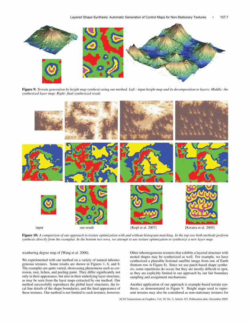
Figure 9: Terrain generation by height map synthesis using our method. Left : input height map and its decomposition to layers; Middle: thesynthesized layer map; Right: final synthesized result.
input our result [Kopf et al. 2007] [Kwatra et al. 2005]
Figure 10: A comparison of our approach to texture optimization with and without histogram matching. In the top row both methods performsynthesis directly from the exemplar. In the bottom two rows, we attempt to use texture optimization to synthesize a new layer map.
weathering degree map of [Wang et al. 2006].
We experimented with our method on a variety of natural inhomo-geneous textures. Some results are shown in Figures 1, 6, and 8.The examples are quite varied, showcasing phenomena such as cor-rosion, rust, lichen, and peeling paint. They differ significantly notonly in their appearance, but also in their underlying layer structure,as may be seen from the layer maps extracted by our method. Ourmethod successfully reproduces the global layer structures, the lo-cal fine details of the shape boundaries, and the final appearance ofthese textures. Our method is not limited to such textures, however.
Other inhomogeneous textures that exhibits a layered structure withnested shapes may be synthesized as well. For example, we havesynthesized a plausible fictional satellite image from one of Earth(bottom row in Figure 8). Since we use patch-based shape synthe-sis, some repetitions do occur, but they are mostly difficult to spot,as they are explicitly limited in our approach by our fair boundarysampling and assignment mechanisms.
Another application of our approach is example-based terrain syn-thesis, as demonstrated in Figure 9. Height maps used to repre-sent terrains may also be considered as non-stationary textures for
Layered Shape Synthesis: Automatic Generation of Control Maps for Non-Stationary Textures • 107:7
ACM Transactions on Graphics, Vol. 28, No. 5, Article 107, Publication date: December 2009.
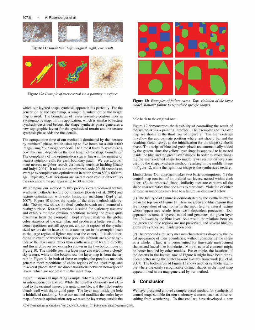
Figure 11: Inpainting. Left: original, right: our result.
Figure 12: Example of user control via a painting interface.
which our layered shape synthesis approach fits perfectly. For thegeneration of the layer map, a simple quantization of the heightmap is used. The boundaries of layers resemble contour lines ina topographic map. In this application, which is similar to texturesynthesis described before, the shape synthesis phase generates anew topographic layout for the synthesized terrain and the texturesynthesis phase adds the fine details.
The computation time of our method is dominated by the “textureby numbers” phase, which takes up to five hours for a 800× 600image using 5×5 neighborhoods. The time it takes to synthesize anew layer map depends on the total length of the shape boundaries.The complexity of the optimization step is linear in the number ofnearest neighbor calls for each boundary patch. We use approxi-mate nearest neighbor search via locally sensitive hashing [Datarand Indyk 2004]. It takes our unoptimized code 20–30 seconds onaverage to complete one optimization iteration for an 800×600 im-age. Typically, 5–10 iterations are used at each resolution level, sothe execution time per layer is up to 30 minutes.
We compare our method to two previous example-based texturesynthesis methods: texture optimization [Kwatra et al. 2005] andtexture optimization with color histogram matching [Kopf et al.2007]. Figure 10 shows the results of the three methods side-by-side. The top row shows the final synthesis result on a texture of arusting surface. Kwatra’s method is suited for stationary textures,and exhibits multiple obvious repetitions making the result quitedissimilar from the exemplar. Kopf’s result matches the globalcolor statistics of the exemplar, and produces a better result, butsome repetitions are still apparent, and some regions of the synthe-sized texture do not have a similar counterpart in the exemplar (suchas the large region of lighter rust near the center). It is also inter-esting to examine whether these previous methods are able to syn-thesize the layer map, rather than synthesizing the texture directly,and this is done on two examples shown in the two bottom rows ofFigure 10. The middle row is a layer map extracted from a cloudysky texture, while in the bottom row the layer map is from the ter-rain in Figure 9. In both of these examples, the previous methodsgenerate more repetitions of entire regions of the layer map, andin several places there are direct transitions between non-adjacentlayers, which are not present in the input map.
Figure 11 shows an inpainting example, where a hole is filled insidean inhomogeneous texture. While the result is obviously not iden-tical to the original image, it is quite plausible, and the filled regionblends well with the original parts. The layer map inside the holeis initialized randomly. Since our method modifies the entire layermap, after each optimization step we reset the layer map outside the
Figure 13: Examples of failure cases. Top: violation of the layermodel. Bottom: failure to reproduce specific shapes.
hole back to the original one.
Figure 12 demonstrates the feasibility of controlling the result ofthe synthesis via a painting interface. The exemplar and its layermap are shown in the third row of Figure 8. The user sketchesin yellow the approximate position where rust should be, and theresulting sketch serves as the initialization for the shape synthesisphase. Thin strips of blue and green pixels are automatically addedby the system, since the yellow layer shape is supposed to be nestedinside the blue and the green layer shapes. In order to avoid chang-ing the user sketched shape too much, fewer resolution levels areused by the shape synthesis method, resulting in the middle imagein Figure 12, while the rightmost image is the synthesized texture.
Limitations: Our approach makes two basic assumptions: (1) thecontrol map consists of an ordered set layers, nested within eachother; (2) the proposed shape similarity measure captures all theshape characteristics that one aims to reproduce. Violation of eitherof these assumptions may lead to a failure, as discussed below.
(1) The first type of failure is demonstrated by the synthetic exam-ple in the top row of Figure 13. Here we green and blue regions thatare independent of each other in the input (e.g., a natural texturewhose appearance results from two independent processes). Ourapproach assumes a layered model and generates the green layerfirst, followed by the blue layer. As a result, the relations betweenthe green and blue regions are not preserved, and several blue re-gions are synthesized inside green ones.
(2) The proposed similarity measure characterizes shapes by the lo-cal appearance of their boundaries, without considering the shapeas a whole. Thus, it is better suited for fine-scale unstructuredshapes and fractal-like boundaries. More structured elements mightbe better handled by other models. For example, the locations ofthe deserts in the bottom row of Figure 8 might have been repro-duced better using the context-aware textures framework [Lu et al.2007]. The bottom row of Figure 13 shows another synthetic exam-ple where the easily recognizable distinct shapes in the input mapappear mixed in the map generated by our method.
5 Conclusion
We have presented a novel example-based method for synthesis ofcontrol maps suitable for non stationary textures, such as those re-sulting from weathering. To that end, we have developed a new
107:8 • A. Rosenberger et al.
ACM Transactions on Graphics, Vol. 28, No. 5, Article 107, Publication date: December 2009.
powerful example-based shape synthesis algorithm that representsshapes as a collection of boundary patches at multiple resolution,and synthesizes a new shape from an example by optimizing a bidi-rectional similarity function. Applications of our method includesynthesis of natural textures and terrain generation.
In future work we hope to extend the method of shape synthesis toa larger set of textures, for example, textures that do not exhibit aclear hierarchy of layers, and textures with larger structures. Ourcurrent measure emphasizes boundary similarity over other prop-erties, such as area to boundary length ratio, which is maintainedonly implicitly. We would like to gain a better understanding ofthe relations between such properties, and experiment with variousextensions of our similarity measure.
We would also like to discover additional applications of our shapesynthesis approach. In particular, it would be interesting to explorethe applicability of such an approach to the synthesis of 3D shapes.
Acknowledgments: This work was supported in part by grantsfrom the Israel Ministry of Science, and from the Israel ScienceFoundation founded by the Israel Academy of Sciences and Hu-manities. The authors would also like to thank the anonymous re-viewers whose suggestions were greatly helpful.
References
ASHIKHMIN, M. 2001. Synthesizing natural textures. InProc. Symp. Interactive 3D Graphics, 217–226.
BHAT, P., INGRAM, S., AND TURK, G. 2004. Geometric texturesynthesis by example. In SGP ’04: Proceedings of the 2004 Eu-rographics/ACM SIGGRAPH symposium on Geometry process-ing, ACM, New York, NY, USA, 41–44.
BOSCH, C., PUEYO, X., MERILLOU, S., AND GHAZANFAR-POUR, D. 2004. A physically-based model for rendering realis-tic scratches. Computer Graphics Forum 23, 3 (Sept.), 361–370.
DATAR, M., AND INDYK, P. 2004. Locality-sensitive hashingscheme based on p-stable distributions. In Proc. SCG ’04, ACMPress, 253–262.
DESBENOIT, B., GALIN, E., AND AKKOUCHE, S. 2004. Simu-lating and modeling lichen growth. Computer Graphics Forum23, 3 (Sept.), 341–350.
DORSEY, J., AND HANRAHAN, P. 1996. Modeling and renderingof metallic patinas. In Proc. SIGGRAPH ’96, Addison Wesley,387–396.
DORSEY, J., EDELMAN, A., JENSEN, H. W., LEGAKIS, J., ANDPEDERSEN, H. K. 1999. Modeling and rendering of weatheredstone. In Proc. SIGGRAPH ’99, ACM Press, 225–234.
DORSEY, J., RUSHMEIER, H., AND SILLION, F. 2008. DigitalModeling of Material Appearance. Computer Graphics. MorganKaufmann / Elsevier, Dec. . 336 pages.
EFROS, A. A., AND FREEMAN, W. T. 2001. Image quilting fortexture synthesis and transfer. Proc. SIGGRAPH 2001, 341–346.
EFROS, A. A., AND LEUNG, T. K. 1999. Texture synthesis bynon-parametric sampling. Proc. ICCV ’99 2, 1033–1038.
GU, J., TU, C.-I., RAMAMOORTHI, R., BELHUMEUR, P., MA-TUSIK, W., AND NAYAR, S. 2006. Time-varying surface ap-pearance: acquisition, modeling and rendering. ACM Transac-tions on Graphics 25, 3 (Proc. SIGGRAPH 2006), 762–771.
HEEGER, D. J., AND BERGEN, J. R. 1995. Pyramid-based textureanalysis/synthesis. Proc. SIGGRAPH ’95, 229–238.
HERTZMANN, A., JACOBS, C. E., OLIVER, N., CURLESS, B.,AND SALESIN, D. H. 2001. Image analogies. Proc. SIGGRAPH2001, 327–340.
HERTZMANN, A., OLIVER, N., CURLESS, B., AND SEITZ, S. M.2002. Curve analogies. In Proc. 13th Eurographics Workshopon Rendering, Eurographics Association, 233–246.
KOPF, J., FU, C.-W., COHEN-OR, D., DEUSSEN, O., LISCHIN-SKI, D., AND WONG, T.-T. 2007. Solid texture synthesis from2d exemplars. ACM Transactions on Graphics 26, 3 (Proc. SIG-GRAPH 2007), 2.
KWATRA, V., SCHODL, A., ESSA, I., TURK, G., AND BOBICK,A. 2003. Graphcut textures: image and video synthesis usinggraph cuts. ACM Transactions on Graphics 22, 3 (Proc. SIG-GRAPH 2003), 277–286.
KWATRA, V., ESSA, I., BOBICK, A., AND KWATRA, N. 2005.Texture optimization for example-based synthesis. ACM Trans-actions on Graphics 24, 3 (Proc. SIGGRAPH 2005), 795–802.
LEFEBVRE, S., AND HOPPE, H. 2006. Appearance-space tex-ture synthesis. ACM Transactions on Graphics 25, 3 (Proc. SIG-GRAPH 2006), 541–548.
LU, J., GEORGHIADES, A. S., GLASER, A., WU, H., WEI,L.-Y., GUO, B., DORSEY, J., AND RUSHMEIER, H. 2007.Context-aware textures. ACM Trans. Graph. 26, 1, 3.
MERILLOU, S., DISCHLER, J.-M., AND GHAZANFARPOUR, D.2001. Corrosion: simulating and rendering. In Proc. GraphicsInterface 2001, Canadian Information Processing Society, 167–174.
SCHRIJVER, A. 2003. Combinatorial Optimization: Polyhedraand Efficiency, vol. A. Springer-Verlag, Berlin Heidelberg.
SIMAKOV, D., CASPI, Y., SHECHTMAN, E., AND IRANI, M.2008. Summarizing visual data using bidirectional similarity.In Proc. CVPR 2008, IEEE Computer Society.
VARMA, M., AND ZISSERMAN, A. 2003. Texture classification:Are filter banks necessary. In Proc. CVPR 2003, IEEE, 691–698.
WANG, J., TONG, X., LIN, S., PAN, M., WANG, C., BAO, H.,GUO, B., AND SHUM, H.-Y. 2006. Appearance manifolds formodeling time-variant appearance of materials. ACM Transac-tions on Graphics 25, 3 (Proc. SIGGRAPH 2006), 754–761.
WEI, L.-Y., AND LEVOY, M. 2000. Fast texture synthesis us-ing tree-structured vector quantization. Proc. SIGGRAPH 2000,479–488.
WEI, L.-Y., HAN, J., ZHOU, K., BAO, H., GUO, B., AND SHUM,H.-Y. 2008. Inverse texture synthesis. ACM Trans. Graph. 27,3, 1–9.
WEI, L.-Y., LEFEBVRE, S., KWATRA, V., AND TURK, G., 2009.State of the art in example-based texture synthesis. Eurographics2009 State of The Art Report, April.
WEXLER, Y., SHECHTMAN, E., AND IRANI, M. 2004. Space-time video completion. In Proc. CVPR 2004, vol. 1, 120–127.
ZHANG, J., ZHOU, K., VELHO, L., GUO, B., AND SHUM, H.-Y. 2003. Synthesis of progressively-variant textures on arbi-trary surfaces. ACM Transactions on Graphics 22, 3 (Proc. SIG-GRAPH 2003), 295–302.
Layered Shape Synthesis: Automatic Generation of Control Maps for Non-Stationary Textures • 107:9
ACM Transactions on Graphics, Vol. 28, No. 5, Article 107, Publication date: December 2009.