Latest developments in LISA PathFinder and the … · LISA PathFinder and the Munich Test Alberto...
42
IGWM-2, 15-Feb-2012 A. Lobo, LPF and the OSTT 1 Latest developments in Latest developments in LISA PathFinder and the LISA PathFinder and the Munich Test Munich Test Alberto Lobo ICE (CSIC) & IEEC
-
Upload
nguyenminh -
Category
Documents
-
view
219 -
download
0
Transcript of Latest developments in LISA PathFinder and the … · LISA PathFinder and the Munich Test Alberto...

IGWM-2, 15-Feb-2012 A. Lobo, LPF and the OSTT 1
Latest developments inLatest developments inLISA PathFinder and theLISA PathFinder and the
Munich TestMunich Test
Alberto LoboICE (CSIC) & IEEC

IGWM-2, 15-Feb-2012 A. Lobo, LPF and the OSTT 2
Plan of talk
1. LISA PathFinder and the LTP2. The Diagnostics subsystem and the DMU
a. Magnetic diagnosticsb. Radiation Monitorc. Thermal diagnosticsd. The DMU, payload computer
3. The OSTT in Munich, Oct-Nov 2011:a. The TOQMb. Test Pland. DI heaters runs
4. Conclusion

IGWM-2, 15-Feb-2012 A. Lobo, LPF and the OSTT 3
1. One LISA arm is squeezed to 30 centimetres:
2. Relax sensitivity by one order of magnitude, also in band:
30 cm
LTP Objectives :
• Drag-free• Interferometry• Phasemeter• Diagnostics• Telemetry• Data processing
LPF basic concept
S Δaω ≤ 3×10⁻¹⁴[1 ω/2π3 mHz
2
] m s−2 Hz−1 /2 , 1 mHz ≤ ω/2π ≤ 30 mHz

IGWM-2, 15-Feb-2012 A. Lobo, LPF and the OSTT 4
LTPLTP

IGWM-2, 15-Feb-2012 A. Lobo, LPF and the OSTT 5
Parts of the DDS(Data and Diagnostics Subsystem)
Diagnostics items:
• Purpose:– Noise split up
• Sensors for:– Temperature– Magnetic fields– Charged particles
• Calibration:– Heaters– Induction coils

IGWM-2, 15-Feb-2012 A. Lobo, LPF and the OSTT 6
Problem: to assess the contribution of a given perturbation to
the total noise, f.Approach: 1) Apply controlled perturbation α to the system
2) Measure “feed-through” coefficient between force and perturbation:
3) Measure actual α with suitable sensors
4) Estimate contribution of α by linear interpolation:
5) Subtract out from total detected noise:
6) Iterate process for all identified perturbations
Noise reduction philosophy
F =∂ f∂
f lin = F
f reduced = f − f lin

IGWM-2, 15-Feb-2012 A. Lobo, LPF and the OSTT 7
Temperature and temperature gradients:– Sensors: thermometers at suitable locations– Control: heaters at suitable locations
Magnetic fields and magnetic field gradients:– Sensors: magnetometers at suitable locations– Control: induction coils at suitable locations
Charged particle showers (mostly protons):– Sensors: Radiation Monitor– Control: N/A
Various diagnostics items

IGWM-2, 15-Feb-2012 A. Lobo, LPF and the OSTT 8
Magnetic sensors
4 tri-axial fluxgates Somewhat distant from TMs

IGWM-2, 15-Feb-2012 A. Lobo, LPF and the OSTT 9
Magnetic field in LTP
Basically caused by spacecraft sources Profile has a clear trough between TMs Linear interpolation is strongly biased (up to 1000%)

IGWM-2, 15-Feb-2012 A. Lobo, LPF and the OSTT 10
Neural network interpolation
12 B-readoutchannels
16 B + ∂B valuesat TM locations
Much improved performance: 5-10% Reliable net training is an issue

IGWM-2, 15-Feb-2012 A. Lobo, LPF and the OSTT 11
Thinking of future GW missions
LTP fluxgate magnetometers have excellent sensitivity, but: They are large → poor space resolution Only a few can be installed They are far from TMs Field and gradient interpolation have unreliabilities
Alternatives are currently investigated at IEEC, e.g. AMRs: They are small → increased significantly space resolution Many can be installed, and closer to TMs Possible back-action sets limits to proximity –under study Detailed field reconstruction accessible Sensitivity is already better than fluxgate's, and improving

IGWM-2, 15-Feb-2012 A. Lobo, LPF and the OSTT 12
Thinking of future GW missions

IGWM-2, 15-Feb-2012 A. Lobo, LPF and the OSTT 13
Thinking of future GW missions

IGWM-2, 15-Feb-2012 A. Lobo, LPF and the OSTT 14
Thinking of future GW missions

IGWM-2, 15-Feb-2012 A. Lobo, LPF and the OSTT 15
Thinking of future GW missions

IGWM-2, 15-Feb-2012 A. Lobo, LPF and the OSTT 16
Calibration coils
Induction coils cangenerate controlledmagnetic fields.
Analysis of TM responsepermits to estimatesusceptibility andremnant magneticmoments of TMs
Magnetic noise can thenbe precisely quantified

IGWM-2, 15-Feb-2012 A. Lobo, LPF and the OSTT 17
The LPF Radiation Monitor
EQM Radiation Monitor
RM concept
RM shield

IGWM-2, 15-Feb-2012 A. Lobo, LPF and the OSTT 18
– The LPF RM lies outside the LTP, hence is not shielded against incoming particles.
– It is based on a two PIN diodes in telescopic configuration.
– In order for it to be sensitive only to E > 70 MeV, the PINs are placed in the interior of a copper cube, some 6 mm thick, which will prevent particles with energies below that threshold from hitting the detector devices:
The LPF Radiation Monitor

IGWM-2, 15-Feb-2012 A. Lobo, LPF and the OSTT 19
The LPF Radiation Monitor: PSI 2010
RM
Beamcollimator
Beam line

IGWM-2, 15-Feb-2012 A. Lobo, LPF and the OSTT 20
The LTP thermal diagnostics items
– 24 high precision temperature sensors (NTCs)
– 14 precision heaters for noise calibration (NTC + kapton)

IGWM-2, 15-Feb-2012 A. Lobo, LPF and the OSTT 21
The LTP thermal diagnostics items

IGWM-2, 15-Feb-2012 A. Lobo, LPF and the OSTT 22
Precision thermometers
LTP temperature sensors

IGWM-2, 15-Feb-2012 A. Lobo, LPF and the OSTT 23
Precision heaters
– Heat effects are usually difficult to model/study in complex systems like the LTP: Radiation pressure Radiometer effect Outgassing Thermo-elastic phenomena Opto-elastic (induced e.g. from previous) ...
– Analytic approach is thus impracticable in essentially all cases of interest
– Numerical modelling (ESATAN and more) is necessary
– A (copyrighted) model of the LTP exists, which can be (and is) used to define and quantify heater activation schemes
– That allows for a calibration procedure of the sensors as regards the effect of temperature fluctuations on the LTP performance
– Like all models, though, these have to be validated by experiment

IGWM-2, 15-Feb-2012 A. Lobo, LPF and the OSTT 24
Precision heaters
* There are three sets of precision heaters in the LTP
* Total number is 14
* Signals are injected from DMU, normally periodic (square) pulses in the LTP MBW
Placement Type Resistance Peak power Comments
EH walls NTCVariable,2 kΩ at 298K
45 mWPairs of NTCs form single “logical” heaters
OW flanges Kapton 45 Ω 1 W --
Suspension srtuts Kapton 44 Ω 2 W
Only 6 out of 8 struts have a heater
FG
2005

IGWM-2, 15-Feb-2012 A. Lobo, LPF and the OSTT 25
Precision heaters
* There are three sets of precision heaters in the LTP
* Total number is 14
* Signals are injected from DMU, normally periodic (square) pulses in the LTP MBW
Placement Type Resistance Peak power Comments
EH walls NTCVariable,2 kΩ at 298K
45 mWPairs of NTCs form single “logical” heaters
OW flanges Kapton 45 Ω 1 W --
Suspension srtuts Kapton 44 Ω 2 W
Only 6 out of 8 struts have a heater
FG
2005
OSTT

IGWM-2, 15-Feb-2012 A. Lobo, LPF and the OSTT 26
The DMU
• Purpose:– LTP computer
• Hardware:
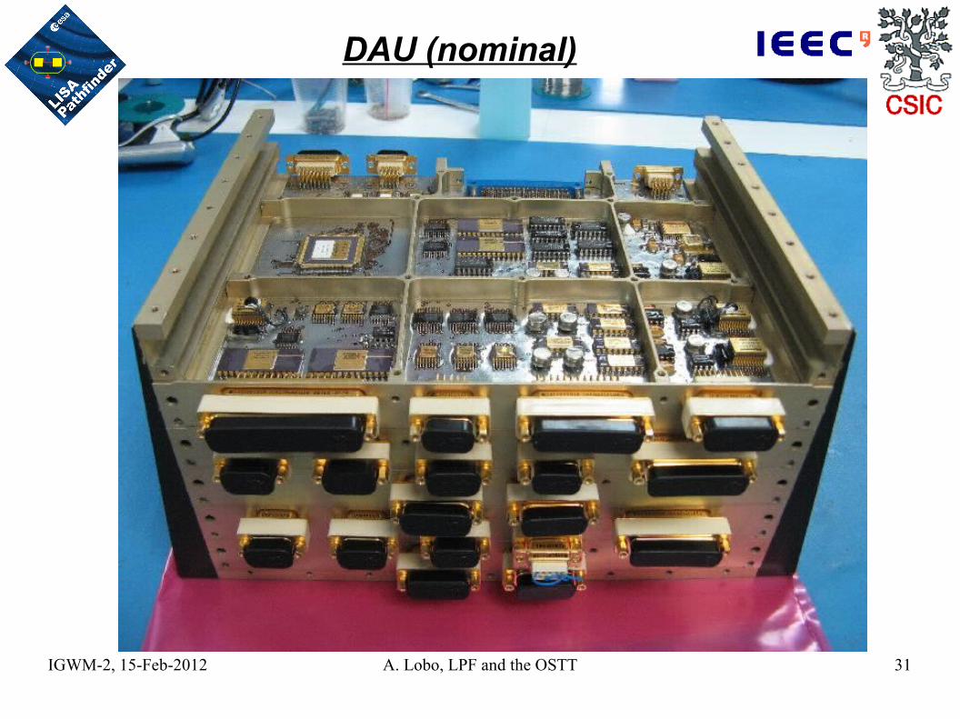
– Power Distribution Unit (PDU)– Data Acquisition Unit (DAU)– Data Processing Unit (DPU)
• Software:
– Boot SW– Application SW:
Diagnostics items Interfaces: routing to and from OBC
HK acquisition and monitor PM acquisition and processing (DFACS) Laser loop controls
Fully redundant
Fully redundant
Parts of the DDS(Data and diagnostics subsystem)

IGWM-2, 15-Feb-2012 A. Lobo, LPF and the OSTT 27
DMU interfaces

IGWM-2, 15-Feb-2012 A. Lobo, LPF and the OSTT 28
DMU chassis

IGWM-2, 15-Feb-2012 A. Lobo, LPF and the OSTT 29
PDU (nominal)

IGWM-2, 15-Feb-2012 A. Lobo, LPF and the OSTT 30
DPU (nominal)
MIL-STD-1553 Bus(OBC & LTP)
CPU (ERC-32)
EEPROM
CPU (ERC-32)
FPGAPROM
RAM
IGWM-2, 15-Feb-2012 A. Lobo, LPF and the OSTT 31
DAU (nominal)

IGWM-2, 15-Feb-2012 A. Lobo, LPF and the OSTT 32
DMU (finished)

IGWM-2, 15-Feb-2012 A. Lobo, LPF and the OSTT 33
The Munich On Station Thermal Test (OSTT)3 Oct 2011 – 17 Nov 2011

IGWM-2, 15-Feb-2012 A. Lobo, LPF and the OSTT 34Harness
DTA
TOQM

IGWM-2, 15-Feb-2012 A. Lobo, LPF and the OSTT 35
Flight representative parts: OMS: RLU, LMU, LCU, OBI ULU IS FEE DMU RM & Magnetometers Suspension Struts (SS) DI SS heaters DI TS at SS and OB
Non-Flight representative parts: TM dummies No OWs No CM No ISH2 harness OBI wrapped in Al foil Rest of DI TS, placed elsewhere
TOQM summary

IGWM-2, 15-Feb-2012 A. Lobo, LPF and the OSTT 36
OSTT at IABG, Munich Oct-Nov 2011

IGWM-2, 15-Feb-2012 A. Lobo, LPF and the OSTT 37
OSTT at IABG, Munich Oct-Nov 2011

IGWM-2, 15-Feb-2012 A. Lobo, LPF and the OSTT 38
OSTT test plan

IGWM-2, 15-Feb-2012 A. Lobo, LPF and the OSTT 39
OSTT at IABG, DI cyclings, TP-14

IGWM-2, 15-Feb-2012 A. Lobo, LPF and the OSTT 40
OSTT at IABG, single ST heaters

IGWM-2, 15-Feb-2012 A. Lobo, LPF and the OSTT 41
Conclusions
– DIs are an essential part of the LTP. Nominally, they work OK
– DMU is working very well, ASW 3.4 is stable
– OSTT has shown that: OMS works largely better than requirement Thermal stability is also fully compliant Diagnostics thermal cyclings produce expected response levels Test report is due mid March-2012
– Raw test data will be made available to IEEC for detailed analysis
– LPF is in good state several months ahead of launch

IGWM-2, 15-Feb-2012 A. Lobo, LPF and the OSTT 42
End of presentationEnd of presentation