Lateral Buckling of Textile Composite Cantilever Beams ... · warp knitting there are multiple...
8
Lateral Buckling of Textile Composite Cantilever Beams with Central Cutouts Bertan Beylergil 1 , Alaattin Aktas 2 and Mehmet Aktas 3 1 Department of Mechanical Engineering, Faculty of Engineering, Izmir Institute of Technology, 35437 Urla, Izmir, Turkey 2 Department of Mechanical Engineering, Faculty of Engineering, Istanbul University, 34320 Avcılar, Istanbul, Turkey 3 Department of Mechanical Engineering, Faculty of Engineering, Usak University, 64120 Usak, Turkey Abstract - The aim of this study is to investigate the effects of knitting tightness level and some geometric parameters such as the shape of cut-out, bluntness and cut-out orientation on the lateral buckling load of weft-knitted 1x1 rib composite cantilever beams with central cut-outs. Four different cut-out shapes are considered; circle, square, regular triangle and elliptical. The results show that the lateral buckling load decreases with the increase of knitting tightness. The lateral buckling load decreases gradually while the cutout shape changed from elliptical to triangle which means big cut-outs cause the weakest beams under the lateral buckling load. Cut- out bluntness and orientation have negligible effect on the lateral buckling load. 1. INTRODUCTION Textile composites are being increasingly used in advanced structures in aerospace, automobile, and marine industries. They have many advantages such as ease of handling, high adaptability, light weight, and high specific stiffness. Textile composites can be divided into three basic categories according to the textile forming techniques used for composite reinforcement: (i) woven fabrics, (ii) knitted fabrics, and (iii) braided fabrics. Compared to the other conventional textile fabrics, knitted fabrics possess high productivity and low cost. Additionally, knitted fabric composites are usually more isotropic than woven fabric composites and they have higher extensibility which means better formability to fit in complicated shapes. All these advantages of knitted composite materials have motivated the researchers to investigate their properties [1]. There are two types of knitted fabric those manufactured by (i) weft knitting and (ii) warp knitting. For weft knitting there is only a single feed of yarn coming into the machine at 90 0 to the direction of fabric production and this yarn forms a row of knit loops across the width of the fabric. In warp knitting there are multiple yarns being fed into the machine in the direction of fabric production, and each yarn forms a line of knit loops in the fabric direction. The knitting directions are also named wale and course. It is well known that thin composite beams are very susceptible to flexural–torsional/lateral buckling depending on the geometry of the cross-section, the material properties, and the boundary and loading conditions. Hindman et al. [2] has determined of lateral-torsional buckling loads of composite woods having a rectangular cross-section. Turvey[3] conducted a series of tests on rectangular cross- section pultruded GRP cantilever beams, which are loaded in their stiffer plane of symmetry by means of a single point load acting through the centroid of the cross-section at the free end. Karaagac et al. [4] calculated the critical buckling loads of laminated composite cantilever beams having rectangular cross-sections, subjected to vertical end loading, by using FEM. Lawson et al. [5] have investigated lateral buckling behaviors of I-section composite cellular beams, subjected to uniform distributed loads, by using both FEM and experimental studies. Brooks and Turvey[6] conducted a series of tests in order to investigate the lateral buckling behavior of pultruded GRP I-section cantilever beams. Eryigit et al. [7] investigated the effects of hole diameter and hole location on the lateral buckling behavior of woven fabric laminated composite cantilever beams.Erklig et al. [8] investigated the effects of different cutouts (circular, square, triangular and elliptical) on the lateral buckling behavior of composite beams made of polymer matrix composites.However, no specific work has been done so far for related to the weft-knitted composite beams subjected to lateral loading. In this study, the lateral buckling behaviour of 1x1 rib knitting glass/epoxy perforated laminated beams investigated numerically. The weft-knitted composite plates are manufactured in three different tightness levels, namely low (K 1 ), medium (K 2 ), and high (K 3 ). The mechanical properties of the plates are determined according to ASTM standards. Determined mechanical properties are used in the numerical analyses. Four different parameters are investigated; knitting tightness levels (low, medium and high), the shapes of central-polygonal cut-outs (triangle, square, circular and elliptical), and bluntness (a counter measure of radius ratio, r/R) and orientation of polygonal cut-outs (θ). In order to investigate the effect of these parameters on the lateral buckling behaviour, ANSYS software package is used. Validation of the numerical model is done by using experimental data from the literature. 166 International Journal of Engineering Research & Technology (IJERT) Vol. 3 Issue 2, February - 2014 ISSN: 2278-0181 www.ijert.org IJERTV3IS20249
-
Upload
phunghuong -
Category
Documents
-
view
222 -
download
0
Transcript of Lateral Buckling of Textile Composite Cantilever Beams ... · warp knitting there are multiple...

Lateral Buckling of Textile Composite Cantilever
Beams with Central Cutouts
Bertan Beylergil
1, Alaattin Aktas
2 and Mehmet Aktas
3
1 Department of Mechanical Engineering, Faculty of Engineering, Izmir Institute of Technology, 35437 Urla, Izmir, Turkey
2Department of Mechanical Engineering, Faculty of Engineering, Istanbul University, 34320 Avcılar, Istanbul, Turkey
3Department of Mechanical Engineering, Faculty of Engineering, Usak University, 64120 Usak, Turkey
Abstract - The aim of this study is to investigate the effects of
knitting tightness level and some geometric parameters such as
the shape of cut-out, bluntness and cut-out orientation on the
lateral buckling load of weft-knitted 1x1 rib composite
cantilever beams with central cut-outs. Four different cut-out
shapes are considered; circle, square, regular triangle and
elliptical. The results show that the lateral buckling load
decreases with the increase of knitting tightness. The lateral
buckling load decreases gradually while the cutout shape
changed from elliptical to triangle which means big cut-outs
cause the weakest beams under the lateral buckling load. Cut-
out bluntness and orientation have negligible effect on the
lateral buckling load.
1. INTRODUCTION
Textile composites are being increasingly used in
advanced structures in aerospace, automobile, and marine
industries. They have many advantages such as ease of
handling, high adaptability, light weight, and high specific
stiffness. Textile composites can be divided into three basic
categories according to the textile forming techniques used
for composite reinforcement: (i) woven fabrics, (ii) knitted
fabrics, and (iii) braided fabrics. Compared to the other
conventional textile fabrics, knitted fabrics possess high
productivity and low cost. Additionally, knitted fabric
composites are usually more isotropic than woven fabric
composites and they have higher extensibility which means
better formability to fit in complicated shapes. All these
advantages of knitted composite materials have motivated
the researchers to investigate their properties [1].
There are two types of knitted fabric those manufactured
by (i) weft knitting and (ii) warp knitting. For weft knitting
there is only a single feed of yarn coming into the machine
at 900 to the direction of fabric production and this yarn
forms a row of knit loops across the width of the fabric. In
warp knitting there are multiple yarns being fed into the
machine in the direction of fabric production, and each yarn
forms a line of knit loops in the fabric direction. The
knitting directions are also named wale and course.
It is well known that thin composite beams are very
susceptible to flexural–torsional/lateral buckling depending
on the geometry of the cross-section, the material properties,
and the boundary and loading conditions. Hindman et al.
[2] has determined of lateral-torsional buckling loads of
composite woods having a rectangular cross-section.
Turvey[3] conducted a series of tests on rectangular cross-
section pultruded GRP cantilever beams, which are loaded
in their stiffer plane of symmetry by means of a single point
load acting through the centroid of the cross-section at the
free end. Karaagac et al. [4] calculated the critical buckling
loads of laminated composite cantilever beams having
rectangular cross-sections, subjected to vertical end loading,
by using FEM. Lawson et al. [5] have investigated lateral
buckling behaviors of I-section composite cellular beams,
subjected to uniform distributed loads, by using both FEM
and experimental studies. Brooks and Turvey[6] conducted
a series of tests in order to investigate the lateral buckling
behavior of pultruded GRP I-section cantilever beams.
Eryigit et al. [7] investigated the effects of hole diameter
and hole location on the lateral buckling behavior of woven
fabric laminated composite cantilever beams.Erklig et al. [8]
investigated the effects of different cutouts (circular, square,
triangular and elliptical) on the lateral buckling behavior of
composite beams made of polymer matrix
composites.However, no specific work has been done so far
for related to the weft-knitted composite beams subjected to
lateral loading.
In this study, the lateral buckling behaviour of 1x1 rib
knitting glass/epoxy perforated laminated beams
investigated numerically. The weft-knitted composite plates
are manufactured in three different tightness levels, namely
low (K1), medium (K2), and high (K3). The mechanical
properties of the plates are determined according to ASTM
standards. Determined mechanical properties are used in
the numerical analyses. Four different parameters are
investigated; knitting tightness levels (low, medium and
high), the shapes of central-polygonal cut-outs (triangle,
square, circular and elliptical), and bluntness (a counter
measure of radius ratio, r/R) and orientation of polygonal
cut-outs (θ). In order to investigate the effect of these
parameters on the lateral buckling behaviour, ANSYS
software package is used. Validation of the numerical model
is done by using experimental data from the literature.
166
International Journal of Engineering Research & Technology (IJERT)
Vol. 3 Issue 2, February - 2014
IJERT
IJERT
ISSN: 2278-0181
www.ijert.orgIJERTV3IS20249
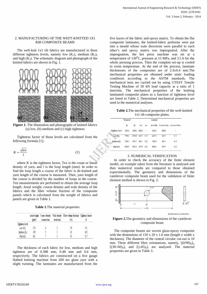
2. MANUFACTURING OF THE WEFT-KNITTED 1X1
RIB COMPOSITE BEAMS
The weft-knit 1x1 rib fabrics are manufactured in three
different tightness levels, namely low (K1), medium (K2),
and high (K3). The schematic diagram and photograph of the
knitted fabrics are shown in Fig. 1.
Figure 1. The illustration and photographs of knitted fabrics
(a) low, (b) medium and (c) high tightness
Tightness factor of those levels are calculated from the
following formula [1];
texK
l (1)
where K is the tightness factor, Tex is the count or linear
density of yarn, and l is the loop length (mm). In order to
find the loop length a course of the fabric is de-knitted and
yarn length of the course is measured. Then, yarn length of
the course is divided by the number of loops in the course.
Ten measurements are performed to obtain the average loop
length. Areal weight, course density and wale density of the
fabrics and the fiber volume fraction of the composite
panels which is calculated from the weight of fabrics and
panels are given in Table 1.
Table 1.The material properties
The thickness of each fabric for low, medium and high
tightness are of 0.388 mm, 0.48 mm and 0.6 mm,
respectively. The fabrics are constructed on a five gauge
flatbed knitting machine from 200 tex glass yarn with a
slight twisting. The laminates are manufactured from the
five layers of the fabric and epoxy matrix. To obtain the flat
composite laminates, the knitted-fabric preforms were put
into a mould whose wale directions were parallel to each
other‟s and epoxy matrix was impregnated. After the
impregnation, the hot press machine was set at a
temperature of 1300C, pressure at 15 MPa, and 3.5 h for the
whole pressing process. Then the complete set-up is cooled
to room temperature. At the end of the process, laminate
thicknesses of the composites are of 2.4±0.4 mm.The
mechanical properties are obtained under static loading
conditions according to the ASTM standards. The
mechanical tests are carried out by using UTEST Tensile
Testing Machine of 50 kN load capacity at a ratio of 1
mm/min. The mechanical properties of the knitting
laminated composite plates as a function of tightness level
are listed in Table 2. Determined mechanical properties are
used in the numerical analyses.
Table 2.The mechanical properties of the weft-knitted
1x1 rib composite plates.
3. NUMERICAL VERIFICATION
In order to check the accuracy of the finite element
model, an example taken from the literature is analysed and
then numerical results are compared to those obtained
experimentally. The geometry and dimensions of the
cantilever composite beam used for the validation of finite
element method is shown in Fig. 2.
Figure 2.The geometry and dimensions of the cantilever
composite beam
The composite beams are woven glass-epoxy composite
with the dimensions of 150 x 20 x 1.6 mm (length x width x
thickness). The diameter of the central circular cut-out is 10
mm. Three different fibre orientations, namely, [(0/90)4]s,
[(30/-60)4]s and [(±45)4]s are analysed. The material
properties are given in Table 3.
Course
Wa
le
(b) (a) (c)
167
International Journal of Engineering Research & Technology (IJERT)
Vol. 3 Issue 2, February - 2014
IJERT
IJERT
ISSN: 2278-0181
www.ijert.orgIJERTV3IS20249

Table 3.The mechanical properties of the laminated
composite beams [8]
One end is clamped and single vertical load was acted at
the free end of the beams in order to calculate lateral
buckling load. The lateral buckling load is determined by
solving for eigenvalues and the corresponding eigenvectors
represents the buckled mode shape. Due to the presence of a
cut-out, smaller and larger number of elements is used in the
vicinity of the cut-outs (Figure 3). Table 4 shows the
comparison of experimental and numerical lateral buckling
values of the composite beam with/without hole for
different fibre orientations and close agreement is found.
Table 4. The comparison of the lateral buckling loads.
Figure3. (a) Mesh structure, (b) boundary and loading
conditions and (c) laterally buckled shape.
4. STATEMENT OF THE PROBLEM
4.1. Case Study-I
The weft-knitted composite beams are of 100 x 25 x 2.4
mm (length x width x thickness). We consider four cut-out
shapes – circle, square, regular triangle and the elliptical.
For the square and triangle cut-outs the concept of
inscribing circle is used, as shown in Fig. 4a, to compare
with the corresponding circular cut-out. The solid-lined
circles are the inscribing circles in the polygons. The
diameter size of the circular cut-out (2R) is 10 mm.
The rotation angle θ represents how the cut-outs are
oriented from the baseline (+x axis) and shown in Fig. 4b.
Due to the symmetry of the polygonal cut-outs, the rotation
angle (θ) increment 3° is applied for the square cut-outs;
hence, a total of fifteen cases are considered from 00 to 45
0.
For the triangle and elliptical cut-outs, the angle of
increment 20 is applied. Therefore, a total of fifteen cases
are considered from 00 to 30
0 for the triangle cut-outs while
a total of forty-five cases are considered from 00 to 90
0 for
the elliptical cut-outs.
As shown in Fig. 4b, a term „bluntness‟ is defined as the
ratio of the edge radius (r) to the inscribing circle radius (R).
Accordingly, bluntness is a counter measure to the radius
ratio (r/R) because bluntness decreases as the radius ratio
increases. For an extreme example, a circular cut-out has a
unit radius ratio but it has zero bluntness. We consider a
total of five different degrees of bluntness including 0.2, 0.4,
0.6, 0.8, and 1.0 for the square and triangular cut-outs.
As shown in Fig. 4c, the diameters of the major and
minor axis dimensions of ellipse are presented by b and c;
respectively. The diameter of the major axis (b) is 10 mm.
c/b ratio are changed from 0.0 to 1.0 with an increment of
0.2. The beams are analysed without a hole when c/b= 0 to
compare the influences having a hole and without a hole
conditions on lateral buckling loads. The elliptical hole is
also positioned as circular hole when c/b = 1, the effect of
circular hole is also analysed at these same conditions.
(a)
(b)
(c)
168
International Journal of Engineering Research & Technology (IJERT)
Vol. 3 Issue 2, February - 2014
IJERT
IJERT
ISSN: 2278-0181
www.ijert.orgIJERTV3IS20249

Figure 4.The illustration of (a) inscribing circle, (b) cut-out
orientation and bluntness, and(c) elliptical cutout
The boundary conditions are taken to be the same as the
model used for the verification. A refine mesh process is
performed for surrounding of the hole due to the close areas
of the cutout is crucial for FEM solutions. The convergence
study is performed to ensure that the number of elements is
enough to give a converged solution. For an example, a
sample mesh structure is shown in Fig. 5. Additionally, the
element number of created some models are presented in
Table 5. In total, 990 models with different cutout shapes
and bluntness have been analysed.
Figure 5.Weft-knitted composite beam with square cut-out
4.2. Case Study-II
The cut-out shapes; circle, square and regular triangle,
but equal areas are considered in this case. As in case study
I, the diameter size of the corresponding circle is 10 mm.
The area of the circular cut-out is 78.539 mm2. Therefore,
length of side of the square cut-out and regular triangular
cut-out are chosen as 8.862 mm and 13.467 mm
respectively.
Table 5. The element and node number of created
models.
Cut-out (θ=0,
c/b=0.2, r/R=0)
Element
number
Node number
Square 2766 3059
Elliptical 2659 2894
Circular 2602 2792
5. RESULTS AND DISCUSSION
5.1. The results of Case Study-I
By considering the design variables– knitting level, cut-
out shape, the degree of bluntness, and cutout rotation-the
critical lateral buckling load is obtained. Table 6 shows the
lateral buckling load with respect to cut-out shape and
knitting level. In this table, an interesting result is that the
lateral buckling loads decreases while the tightness level
increases from low to high. It is also seen that the composite
beams without cut-out have the maximum lateral buckling
load. It is expected, because the stiffness is higher than the
others. The critical lateral buckling load decreases gradually
while the cut-out shape changed from elliptical to triangle.
In case of triangle cut-outs, the critical lateral buckling load
is being the lowest because the area removed from the beam
is greater than the others.
Table 6.The lateral buckling loads (N) with respect to
cut-out shapes and tightness level (c/b=0.2, r/R=0.0, θ=00).
Figure 6 presents the effect of c/b ratio and cut-out
orientation on the lateral buckling load of the cantilever
beam with an elliptical for different knitting tightness levels.
It is observed that the critical lateral buckling load increases
with the increase of cut-out orientation up to 220 then the
lateral buckling load begins to decrease. The lateral
buckling load takes its minimum value when the cut-out
orientation is 900. The lateral buckling load decreases with
the increase of c/b ratio. It is observed that while c/b ratio
increases from 0.2 to 0.8, the cut-out orientation has fewer
effects on the composite beams since the cut-out shape turns
into from elliptical to circular as previously mentioned.
Figure 7 shows variation of lateral buckling load for
square cut-out with bluntness and cut-out orientation. It is
observed that the critical lateral buckling load increases with
the increase of cut-out orientation up to 120 then the lateral
buckling load begins to decrease. The lateral buckling load
takes its minimum value when the cut-out orientation is
oriented at 450. The lateral buckling load increases with the
increase of bluntness. This is because the removed area from
the beam is being reduced. It can be concluded that while
bluntness increases from 0.0 to 1.0, the cut-out orientation
has fewer effects on the composite beams since the cut-out
shape turns into circle.
(a) (b) (c)
169
International Journal of Engineering Research & Technology (IJERT)
Vol. 3 Issue 2, February - 2014
IJERT
IJERT
ISSN: 2278-0181
www.ijert.orgIJERTV3IS20249

Figure 8
shows the effect of bluntness and cut-out orientation on lateral buckling load of the beam with a
triangular cut-out. If degree of θincreases, the lateral
buckling load begins to decreases. The lateral buckling load
takes its maximum value when cut-out
orientation is 00
while the lateral buckling load takes its minimum value
when the cut-out oriented at 300.
Figure 6.
Variation of lateral buckling load for elliptical cut-out
with
different c/b ratio and cut-out orientation (a) low tightness, (b) medium
tightness and (c) high tightness level
(a)
(b)
(c)
Figure 7.Variation of lateral buckling load for square cut-out with bluntness and cut-out orientation (a) low tightness, (b) medium tightness
and (c) high tightness level
(a)
(b)
(c)
170
International Journal of Engineering Research & Technology (IJERT)
Vol. 3 Issue 2, February - 2014
IJERT
IJERT
ISSN: 2278-0181
www.ijert.orgIJERTV3IS20249
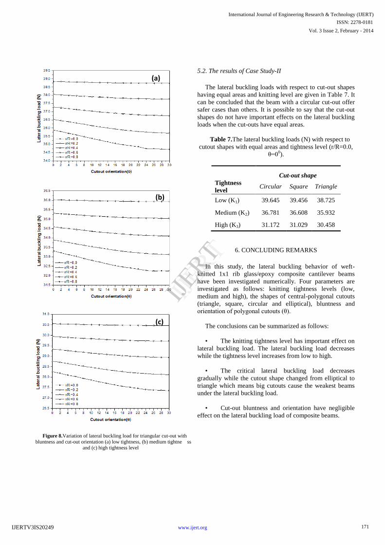
Figure 8.Variation of lateral buckling load for triangular cut-out with
bluntness and cut-out orientation (a) low tightness, (b) medium tightne ss and (c) high tightness level
(a)
(b)
(c)
5.2. The results of Case Study-II
The lateral buckling loads with respect to cut-out shapes
having equal areas and knitting level are given in Table 7. It
can be concluded that the beam with a circular cut-out offer
safer cases than others. It is possible to say that the cut-out
shapes do not have important effects on the lateral buckling
loads when the cut-outs have equal areas.
Table 7.The lateral buckling loads (N) with respect to
cutout shapes with equal areas and tightness level (r/R=0.0,
θ=00).
Cut-out shape
Tightness
levelCircular Square Triangle
Low (K1) 39.645 39.456 38.725
Medium (K2) 36.781 36.608 35.932
High (K3) 31.172 31.029 30.458
6. CONCLUDING REMARKS
In this study, the lateral buckling behavior of weft-
knitted 1x1 rib glass/epoxy composite cantilever beams
have been investigated numerically. Four parameters are
investigated as follows: knitting tightness levels (low,
medium and high), the shapes of central-polygonal cutouts
(triangle, square, circular and elliptical), bluntness and
orientation of polygonal cutouts (θ).
The conclusions can be summarized as follows:
• The knitting tightness level has important effect on
lateral buckling load. The lateral buckling load decreases
while the tightness level increases from low to high.
• The critical lateral buckling load decreases
gradually while the cutout shape changed from elliptical to
triangle which means big cutouts cause the weakest beams
under the lateral buckling load.
• Cut-out bluntness and orientation have negligible
effect on the lateral buckling load of composite beams.
171
International Journal of Engineering Research & Technology (IJERT)
Vol. 3 Issue 2, February - 2014
IJERT
IJERT
ISSN: 2278-0181
www.ijert.orgIJERTV3IS20249
7. REFERENCES
1. Asi, O., Aktas, A., Tercan, M. and Yuksekkaya, M. E.,
2010, “Effect of Knitting Tightness on Mechanical
Properties of Weft-knit Glass Fiber”, Journal of
Reinforced Plastics and Composites, Vol. 29, No. 1, pp.
86-93.
2. Hindman, D. P., Manbeck H. B. and Janowiak, J. J.,
2005, “Measurement and prediction of lateral torsional
buckling loads of composite wood materials:
rectangular sections”, The Forest Products Journal, Vol.
55, No. 9, pp. 42-47.
3. Turvey, G. J., 1996, “Lateral buckling tests on
rectangular cross section pultruded GRP cantilever
beams”, Composites Part B, Vol. 27, No. 1, pp. 35-42.
4. Karaagac, C., Ozturk, H. and Sabuncu, M., 2007,
“Lateral dynamic stability analysis of a cantilever
laminated composite beam with an elastic support”,
International Journal of Structural Stability and
Dynamics, Vol. 7, No. 3, pp. 377-402.
5. Lawson, R. M., Lim, J., Hicks S. J. and Simms, W. I.,
2006, “Design of composite asymmetric cellular beams
and beams with large web openings”, Journal of
Constructional Steel Research, Vol. 62, pp. 614-629.
6. Brooks, R. J. and Turvey, G. J., 1995, “Lateral buckling
of pultruded GRP I-section cantilever”, Composite
Structures, Vol. 32, pp. 203-215.
7. Eryigit, E., Zor, M. and Arman, Y., 2009, “Hole effects
on lateral buckling of laminated cantilever beams”,
Composites Part B, Vol. 40, pp. 174-179.
8. Erklig A., Yeter E. and Bulut M., 2013, “The effects of
cut-outs on lateral buckling behavior of laminated
composite beams”, Composite Structures, Vol. 104,
pp.54-59.
172
International Journal of Engineering Research & Technology (IJERT)
Vol. 3 Issue 2, February - 2014
IJERT
IJERT
ISSN: 2278-0181
www.ijert.orgIJERTV3IS20249