Laser Welding Technical Information - Automation … Welding Radial Weld With radial tools, pressure...
8
Laser Welding A laser is a beam of concentrated light energy generated at a specific wavelength. In nature, light exists across a spectrum of wavelengths, ranging from very short (X-rays and gamma rays) to very long (radio waves). Humans can only see visible or the “white light” wavelengths from around 430-690 nanometers (nm). A laser beam is an amplified concentration of light energy at a specific wavelength. It is coherent light, which allows focusing on a tight spot and a narrow beam over long distances. The word LASER is an acronym that stands for Light Amplification by Stimulated Emission of Radiation. Laser energy absorption of a material varies based on a number of factors, such as wavelength, material thickness, crystalline structure, material additives, molecular structure, and more. The process takes the advantages of these material properties and laser to create a bond between two plastic materials—one that transmits the laser energy and one that absorbs it. Laser Welding Technical Information Transmitted Absorbed Reflected Laser energy source How Laser Welding Works Laser beams change when interacting with material When a laser beam encounters any material such as plastic, it will either be transmitted, reflected, or absorbed based on the wavelength and the composition of the material it encounters. Most materials exhibit some degree of all three effects, but in varying proportions. A material may be optically clear to light in the visible spectrum and very absorptive to infrared laser, or be opaque to our eyes but transparent to infrared laser. Laser beam Reflected laser beam Reflected laser beam Laser beam Amorphous Semi-Crystalline High transmission Internal scattering and absorption of laser beam Amorphous vs. Semi-Crystalline Increasing wavelength ( λ) in nm→ 400 500 600 700 X-rays UV IR Microwave FM AM Radio waves Long radio waves 980 nm Branson’s laser wavelength Increasing wavelength ( λ)→ ← Increasing frequency ( ν ) 10 -16 10 -14 10 -12 10 -10 10 -8 10 -4 10 -2 10 0 10 2 10 4 10 6 10 8 λ (m) 10 24 10 22 10 20 10 18 10 16 10 14 10 12 10 10 10 8 10 6 10 4 10 2 10 0 ν (Hz) Visible spectrum Gamma 400 500 600 700 V isible spectrum 10 -6 Electromagnetic Spectrum
Transcript of Laser Welding Technical Information - Automation … Welding Radial Weld With radial tools, pressure...

Laser Welding
A laser is a beam of concentrated light energy generated at a specific wavelength. In nature, light exists across a spectrum of wavelengths, ranging from very short (X-rays and gamma rays) to very long (radio waves). Humans can only see visible or the “white light” wavelengths from around 430-690 nanometers (nm). A laser beam is an amplified concentration of light energy at a specific wavelength. It is coherent light, which allows focusing on a tight spot and a narrow beam over long distances. The word LASER is an acronym that stands for Light Amplification by Stimulated Emission of Radiation.
Laser energy absorption of a material varies based on a number of factors, such as wavelength, material thickness, crystalline structure, material additives, molecular structure, and more. The process takes the advantages of these material properties and laser to create a bond between two plastic materials—one that transmits the laser energy and one that absorbs it.
Laser Welding Technical Information
Laser beams change when interacting with material
Transmitted
Absorbed
Reflected
Laser energy source
How Laser Welding Works
Laser beams change when interacting with material
When a laser beam encounters any material such as plastic, it will either be transmitted, reflected, or absorbed based on the wavelength and the composition of the material it encounters. Most materials exhibit some degree of all three effects, but in varying proportions. A material may be optically clear to light in the visible spectrum and very absorptive to infrared laser, or be opaque to our eyes but transparent to infrared laser.
Laser beam Reflected laser beam
Reflected laser beam
Laser beam
Amorphous Semi-Crystalline
High transmissionInternal scattering and
absorption of laser beam
Amorphous vs. Semi-Crystalline
Amorphous vs. Semi-Crystalline
Electromagnetic spectrum
Increasing wavelength ( λ) in nm →
400 500 600 700
X-rays UV IR Microwave FM AMRadio waves
Long radio waves
980 nm Branson’s laser wavelength
Increasing wavelength (λ) →
← Increasing frequency ( ν )
10 -16 10 -14 10 -12 10 -10 10-8 10 -4 10 -2 100 102 104 106 108 λ (m)
1024 1022 1020 1018 1016 1014 1012 1010 108 106 104 102 100 ν (Hz)
Visible spectrum
Gamma
400 500 600 700
Visible spectrum
10 -6
Electromagnetic Spectrum
Laser welding is also effective with some dissimilar material combinations. Research and development teams at material suppliers and universities worldwide have been actively advancing the frontier of plastic laser welding. More laser-compatible materials and additives are being developed, and the possibilities are expanding quickly.
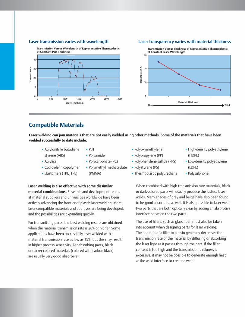
For transmitting parts, the best welding results are obtained when the material transmission rate is 20% or higher. Some applications have been successfully laser welded with a material transmission rate as low as 15%, but this may result in higher process sensitivity. For absorbing parts, black or darker-colored materials (colored with carbon black) are usually very good absorbers.
When combined with high-transmission-rate materials, black or dark-colored parts will usually produce the fastest laser welds. Many shades of gray and beige have also been found to be good absorbers, as well. It is also possible to laser weld two parts that are both optically clear by adding an absorptive interface between the two parts.
The use of fillers, such as glass fiber, must also be taken into account when designing parts for laser welding. The addition of a filler to a resin generally decreases the transmission rate of the material by diffusing or absorbing the laser light as it passes through the part. If the filler content is too high and the transmission thickness is excessive, it may not be possible to generate enough heat at the weld interface to create a weld.
Laser welding can join materials that are not easily welded using other methods. Some of the materials that have been welded successfully to date include:
Compatible Materials
Laser transmission varies with wavelength
40
30
20
10
0
Tran
smis
sion
%
Wavelength (nm)
Laser transmission varies with wavelengthTransmission Versus Wavelength of Representative Thermoplasticat Constant Part Thickness
0 500 1000 1500 2000 2500 3000
Laser transparency varies with material thickness
Transmission Versus Thickness of Representative Thermoplastic at Constant Laser Wavelength
ThickThinMaterial Thickness
30
20
10
0
Tran
smis
sio
n %
Laser transparency varies with material thickness
• Acrylonitrile butadiene
styrene (ABS)
• Acrylics
• Cyclic olefin copolymer
• Elastomers (TPU/TPE)
• Polyoxymethylene
• Polypropylene (PP)
• Polyphenylene sulfide (PPS)
• Polystyrene (PS)
• Thermoplastic polyurethane
• PBT
• Polyamide
• Polycarbonate (PC)
• Polymethyl methacrylate
(PMMA)
• High-density polyethylene
(HDPE)
• Low-density polyethylene
(LDPE)
• Polysulphone

Methods of Laser Welding
Method DescriptionHybrid Methods Combinations of trace laser technology with other joining or warming techniques, such as thermal conduction or non-coherent, infrared warming, to counter some of the disadvantages of trace welding.
Mask Wavelength Utilizes a mask to physically block laser energy from reaching some spots, but permits it where the weld is desired. Laser energy can be applied over a large area, or in a line-shaped beam that travels over the mask. This method is very inefficient, wasteful of laser energy on the mask, and slow.
Roller or Sphere Laser beam shoots through a transparent roller or sphere, which is in contact with the parts and applies welding pressure. There is risk of marking of the part surface when force is applied at a single point. Weld time scales up with weld-line distance.
Semi-simultaneous A single laser beam is fired at a mirror that rotates on several axes to aim the beam to the parts. (a.k.a., Quasi- The part geometry is restricted to certain angles facing the mirror, and the weld line is typically simultaneous) a closed loop.
* Simultaneous Uses one or more laser beams to melt the entire line simultaneously. Beams can be shaped in positiveSTTIr or negative waveguides to create 3-D solutions. This is the best method for large parts and mass production.
Trace A single laser beam travels along the weld line. Weld time scales up with weld distance, and weld depth is not easy to control. High local intensity can lead to burns.
2 µm Wavelength Lasers of different wavelengths can be used. At 2 µm, most materials tend to be absorptive and exhibit volumetric heating throughout the parts. Both upper and lower parts will melt. This process can weld two clear parts, but is generally limited to thin components and 3-D applications prove extremely challenging. A 2 µm, simultaneous welding solution does not exist, so this process is typically slower as the part size grows.
Wide-beam Scan Similar to mask in using physical barriers, but utilizes a waveguide to direct the laser energy. Unlike the mask method, wide beam scan directs most of the energy to the weld line, and is typically much faster.
There are several methods of laser welding: All methods use similar fundamentals of laser energy and absorptive materials to create heat, melt plastic, and form a bond. However, several of the technologies have significant trade-offs to implementation, or are not ideal for applications.
* Branson has dedicated 15 years toward developing and refining the STTIr process to overcome the limitations of trace, semi-simultaneous, and roller/sphere welding. The STTIr’s waveguide can be applied as simultaneous or wide-beam scan methods.
Laser Welding
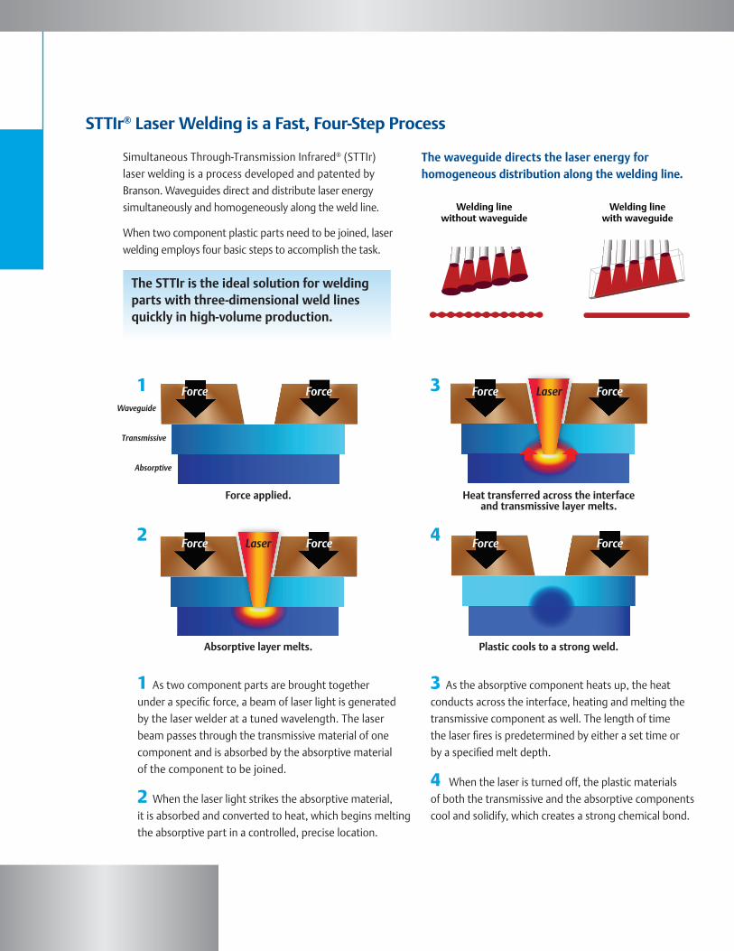
Simultaneous Through-Transmission Infrared® (STTIr) laser welding is a process developed and patented by Branson. Waveguides direct and distribute laser energy simultaneously and homogeneously along the weld line.
When two component plastic parts need to be joined, laser welding employs four basic steps to accomplish the task.
The STTIr is the ideal solution for welding parts with three-dimensional weld lines quickly in high-volume production.
STTIr® Laser Welding is a Fast, Four-Step Process
1 As two component parts are brought together under a specific force, a beam of laser light is generated by the laser welder at a tuned wavelength. The laser beam passes through the transmissive material of one component and is absorbed by the absorptive material of the component to be joined.
2 When the laser light strikes the absorptive material, it is absorbed and converted to heat, which begins melting the absorptive part in a controlled, precise location.
3 As the absorptive component heats up, the heat conducts across the interface, heating and melting the transmissive component as well. The length of time the laser fires is predetermined by either a set time or by a specified melt depth.
4 When the laser is turned off, the plastic materials of both the transmissive and the absorptive components cool and solidify, which creates a strong chemical bond.
1
42
The waveguide directs the laser energy for homogenous distribution along the welding line.
Welding linewithout waveguide
Welding linewith waveguide
The waveguide directs the laser energy for homogeneous distribution along the welding line.
3Waveguide
Transmissive
Absorptive
Force applied.
Force
Force
Force
Force
Force
Force
Force
Force
Laser
Laser
Absorptive layer melts. Plastic cools to a strong weld.
Heat transferred across the interface and transmissive layer melts.
Laser Welding
Radial Weld
With radial tools, pressure is applied on one axis while the laser beam enters on another plane.
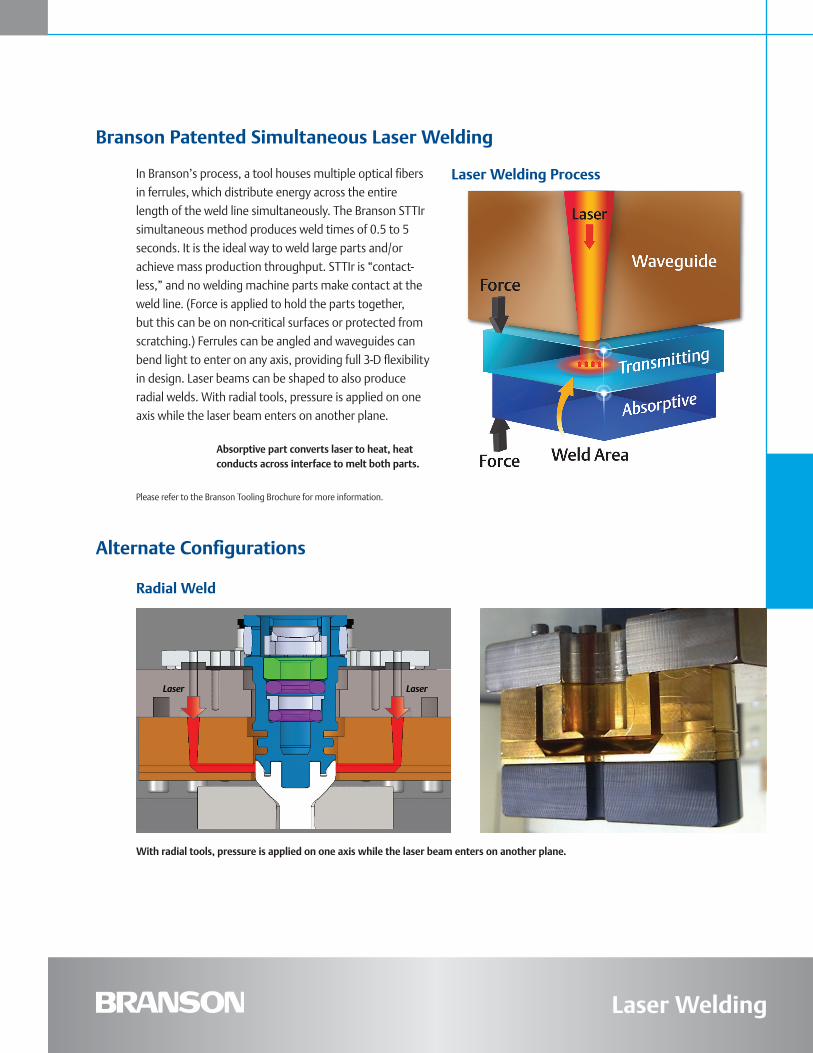
In Branson’s process, a tool houses multiple optical fibers in ferrules, which distribute energy across the entire length of the weld line simultaneously. The Branson STTIr simultaneous method produces weld times of 0.5 to 5 seconds. It is the ideal way to weld large parts and/or achieve mass production throughput. STTIr is “contact-less,” and no welding machine parts make contact at the weld line. (Force is applied to hold the parts together, but this can be on non-critical surfaces or protected from scratching.) Ferrules can be angled and waveguides can bend light to enter on any axis, providing full 3-D flexibility in design. Laser beams can be shaped to also produce radial welds. With radial tools, pressure is applied on one axis while the laser beam enters on another plane.
Branson Patented Simultaneous Laser Welding
Alternate Configurations
Laser Welding Process
Radial Weld
Absorptive part converts laser to heat, heat conducts across interface to melt both parts.
Please refer to the Branson Tooling Brochure for more information.
With radial tools, pressure is applied on one axis while the laser beam enters on another plane.
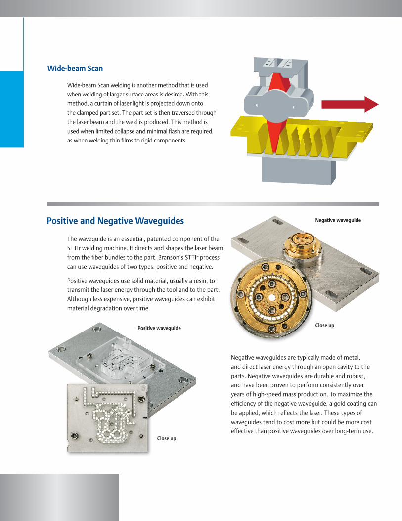
Wide-beam Scan welding is another method that is used when welding of larger surface areas is desired. With this method, a curtain of laser light is projected down onto the clamped part set. The part set is then traversed through the laser beam and the weld is produced. This method is used when limited collapse and minimal flash are required, as when welding thin films to rigid components.
Wide-beam Scan
The waveguide is an essential, patented component of the STTIr welding machine. It directs and shapes the laser beam from the fiber bundles to the part. Branson’s STTIr process can use waveguides of two types: positive and negative.
Positive waveguides use solid material, usually a resin, to transmit the laser energy through the tool and to the part. Although less expensive, positive waveguides can exhibit material degradation over time.
Negative waveguides are typically made of metal, and direct laser energy through an open cavity to the parts. Negative waveguides are durable and robust, and have been proven to perform consistently over years of high-speed mass production. To maximize the efficiency of the negative waveguide, a gold coating can be applied, which reflects the laser. These types of waveguides tend to cost more but could be more cost effective than positive waveguides over long-term use.
Positive and Negative Waveguides
Positive waveguide
Negative waveguide
Close up
Close up

Weld Quality Because the process is non-intrusive, the parts typically exhibit excellent cosmetic properties. The heating/ melting of the parts is very localized, occurring only at the weld interface.
Minimal Flash and No Particulate Since the process can be easily controlled by varying the power of the laser source, it is possible to accurately control the power dissipation within the weld, resulting in less flash. There is also no frictional motion between the parts and therefore no particulate generated.
Part Design Flexibility This method allows for 3-D joint configurations, and is unrestricted with respect to a common weld plane. Many internal weld lines are possible.
Gentle to Sensitive Assemblies Since there is little movement of the parts, no excitation or vibration, sensitive electronic and mechanical assemblies can be welded without damage. Only a clamping force to hold the two parts being welded is needed.
Fast and Flexible Ideal for high-volume applications; a typical weld cycle ranges from 0.5 to 5 seconds.
The Advantages of Branson Laser Welding
Automotive
Branson Laser System Architecture
Medical Business & Consumer Electronics
Laser Welding
A laser bank contains five diodes that generate the laser energy, with closed loop feedback. The energy travels from the bank to the upper tool in flexible, highly purified optical glass fiber bundles. The upper tool directs the laser energy to the part through waveguides. A lower tool holds the part. Force can be applied either from the upper or lower tool, depending on the application and machine configuration. Other components, such as a chiller, human/machine interface, and power supplies are typically located in a different part of the system, or laser support unit.
Fiber bundles
Laser bank
Waveguide and upper tool
Method of actuation
Laser support unit
(Controller, interface, chiller, and power supplies)
Lower tool and part
The Branson Advantage
Laser Welding
AmericasBranson Ultrasonics Corp.41 Eagle RoadDanbury, CT 06810, USAT: 203-796-0400F: 203-796-0450www.bransonultrasonics.com
EuropeBranson UltraschallNiederlassung der EmersonTechnologies GmbH & Co. OHGWaldstrasse 53-5563128 Dietzenbach, GermanyT: +49-6074-497-0F: +49-6074-497-199www.branson.eu
AsiaBranson Ultrasonics (Shanghai) Co., Ltd.758 Rong Le Dong RoadSong Jiang, Shanghai, PRC, 201613T: 86-21-3781-0588F: 86-21-5774-5100 www.branson.com.cn
© B
rans
on U
ltras
onic
s Co
rpor
atio
n 20
16Th
e Em
erso
n lo
go is
a tr
adem
ark
and
serv
ice
mar
k
of E
mer
son
Elec
tric
Co.
Prin
ted
in th
e U
.S.A
. PJ
-000
22-1
6
Note: All sales shall be subject to the Supplier’s terms and conditions of sale in Branson’s quotations and sales contracts.
True Global Support & ServiceBranson is committed to not only engineering and supplying laser welding equipment to meet your needs, but also to providing applications support, employee training, troubleshooting, and ongoing customer service so that your equipment continually operates as expected.
Branson laser equipment is backed by our proven commitment to providing superior global technology, support, and customer service through a worldwide network of 70 offices. Branson, a business of Emerson, is a diversified international manufacturing and technology company committed to developing technological breakthroughs that enhance the performance of a wide range of products and processes.
To learn how Branson’s expertise can help you adapt to industry changes, contact the regional center nearest you.


![PECULIARITIES OF LASER WELDING OF METALS · PECULIARITIES OF LASER WELDING OF METALS ... technological process and also broadened application of this method [1,4]. The laser welding](https://static.fdocuments.us/doc/165x107/5e0d62e12e988379d40e28d6/peculiarities-of-laser-welding-of-peculiarities-of-laser-welding-of-metals-technological.jpg)