Laser damage creates backdoors in quantum communications · PDF fileLaser damage creates...
8
Laser damage creates backdoors in quantum communications Vadim Makarov, 1, 2, 3, 4, a) Jean-Philippe Bourgoin, 2, 3 Poompong Chaiwongkhot, 2, 3 Mathieu Gagn ´ e, 5 Thomas Jennewein, 2, 3, 6 Sarah Kaiser, 2, 3 Raman Kashyap, 5 Matthieu Legr ´ e, 7 Carter Minshull, 2 and Shihan Sajeed 2, 4 1) The rest of the authors are listed alphabetically. 2) Institute for Quantum Computing, University of Waterloo, Waterloo, ON, N2L 3G1 Canada 3) Department of Physics and Astronomy, University of Waterloo, Waterloo, ON, N2L 3G1 Canada 4) Department of Electrical and Computer Engineering, University of Waterloo, Waterloo, ON, N2L 3G1 Canada 5) Department of Engineering Physics and Department of Electrical Engineering, ´ Ecole Polytechnique de Montr´ eal, Montr´ eal, QC, H3C 3A7 Canada 6) Quantum Information Science Program, Canadian Institute for Advanced Research, Toronto, ON, M5G 1Z8 Canada 7) ID Quantique SA, Chemin de la Marbrerie 3, 1227 Carouge, Geneva, Switzerland (Dated: 12 October 2015) Quantum communication protocols such as quantum cloud computing 1 , digital signatures 2 , coin-tossing 3 , secret-sharing 4 , and key distribution 5 , using similar opti- cal technologies, claim to provide unconditional security guaranteed by quantum mechanics. Among these pro- tocols, the security of quantum key distribution (QKD) is most scrutinized and believed to be guaranteed as long as implemented devices are properly characterized and existing implementation loopholes are identified and patched 6,7 . Here we show that this assumption is not true. We experimentally demonstrate a class of attacks based on laser damage 8 , capable of creating new security loop- holes on-demand. We perform it on two different imple- mentations of QKD and coin-tossing protocols, and create new information leakage side-channels. Our results show that quantum communication protocols cannot guarantee security alone, but will always have to be supported by ad- ditional technical countermeasures against laser damage. Cryptography, an art of secure communication, has tra- ditionally relied on either algorithmic or computational complexity 9 . Even the most state-of-the-art classical crypto- graphic schemes do not have a strict mathematical proof to ascertain their security. With the advance of quantum comput- ing, it may be a matter of time before the security of the most widely used public-key cryptography protocols is broken 10 . However, QKD (popularly known as quantum cryptography) 5 allows remote key distribution with unconditional security 6,7 . Its complete security model is based on the laws of quantum mechanics, security proofs and model of equipment. When we go from theory to practice, the practical behaviour of the implemented equipment often deviates from its modeled be- haviour, leading to a compromise of security 11–16 . However, it is widely assumed that as long as these deviations are properly characterized and security proofs are updated accordingly 7,17 , QKD can provide unconditional security. In this work we show that this is not always true for QKD and other secure a) Electronic mail: [email protected] quantum communication protocols. Even if a system is per- fectly characterized and deviations are included into the secu- rity proofs, an eavesdropper can still create a new deviation on-demand, unlike in classical cryptography schemes. The reason behind this is that in classical communication systems, the security-critical parts can be physically separated from the communication channel, thus making them isolated from physical access and alteration by the eavesdropper 18 . However, the front-end of a quantum communication system is essentially an analog optical system connected to the chan- nel, and easily accessible by an eavesdropper. The latter may shoot a high-power laser from the communication channel to damage a security-critical component of the system, render- ing the system insecure 8 . To verify this possibility, we per- form laser damage on two completely different widely used implementations: a commercial fiber-optic system for QKD and coin-tossing with phase-encoded qubits 19,20 , and a free- space system for QKD with polarization-encoded qubits 21 . In both systems, the damage opens up a new side-channel, which can compromise the security of QKD even with today’s technology 16,22 . Although we have only tested implementations of QKD and coin-tossing, the security of other quantum communication protocols seems to rely on broadly similar assumptions, and they use similar optical technology. For example, in quan- tum cloud computing 1 and digital signatures 2 , client’s and Alice’s state preparation may be eavesdropped on. Quan- tum implementations of oblivious transfer 23 and relativistic bit commitment 24 are based on modified QKD setups and thus suffer from the same vulnerabilities. However the implemen- tations and security criteria of those protocols are less devel- oped, making their battle-testing a future task. Laser damage in fiber-optic quantum communication system. To demonstrate the threat of laser damage in a fiber- optic quantum communication implementation, we chose a plug-and-play QKD 19 and loss-tolerant quantum coin tossing (QCT) 3 . Both were implemented using a commercial system Clavis2 from ID Quantique 20 . In both cases, Bob sends bright light pulses to Alice. Alice randomly encodes her secret bits 1 arXiv:1510.03148v1 [quant-ph] 12 Oct 2015
Transcript of Laser damage creates backdoors in quantum communications · PDF fileLaser damage creates...
Laser damage creates backdoors in quantum communicationsVadim Makarov,1, 2, 3, 4, a) Jean-Philippe Bourgoin,2, 3 Poompong Chaiwongkhot,2, 3 Mathieu Gagne,5Thomas Jennewein,2, 3, 6 Sarah Kaiser,2, 3 Raman Kashyap,5 Matthieu Legre,7 Carter Minshull,2 andShihan Sajeed2, 4
1)The rest of the authors are listed alphabetically.2)Institute for Quantum Computing, University of Waterloo, Waterloo, ON, N2L 3G1 Canada3)Department of Physics and Astronomy, University of Waterloo, Waterloo, ON,N2L 3G1 Canada4)Department of Electrical and Computer Engineering, University of Waterloo, Waterloo, ON,N2L 3G1 Canada5)Department of Engineering Physics and Department of Electrical Engineering, Ecole Polytechnique de Montreal,Montreal, QC, H3C 3A7 Canada6)Quantum Information Science Program, Canadian Institute for Advanced Research, Toronto, ON,M5G 1Z8 Canada7)ID Quantique SA, Chemin de la Marbrerie 3, 1227 Carouge, Geneva, Switzerland
(Dated: 12 October 2015)
Quantum communication protocols such as quantumcloud computing1, digital signatures2, coin-tossing3,secret-sharing4, and key distribution5, using similar opti-cal technologies, claim to provide unconditional securityguaranteed by quantum mechanics. Among these pro-tocols, the security of quantum key distribution (QKD)is most scrutinized and believed to be guaranteed aslong as implemented devices are properly characterizedand existing implementation loopholes are identified andpatched6,7. Here we show that this assumption is not true.We experimentally demonstrate a class of attacks basedon laser damage8, capable of creating new security loop-holes on-demand. We perform it on two different imple-mentations of QKD and coin-tossing protocols, and createnew information leakage side-channels. Our results showthat quantum communication protocols cannot guaranteesecurity alone, but will always have to be supported by ad-ditional technical countermeasures against laser damage.
Cryptography, an art of secure communication, has tra-ditionally relied on either algorithmic or computationalcomplexity9. Even the most state-of-the-art classical crypto-graphic schemes do not have a strict mathematical proof toascertain their security. With the advance of quantum comput-ing, it may be a matter of time before the security of the mostwidely used public-key cryptography protocols is broken10.However, QKD (popularly known as quantum cryptography)5
allows remote key distribution with unconditional security6,7.Its complete security model is based on the laws of quantummechanics, security proofs and model of equipment. Whenwe go from theory to practice, the practical behaviour of theimplemented equipment often deviates from its modeled be-haviour, leading to a compromise of security11–16. However, itis widely assumed that as long as these deviations are properlycharacterized and security proofs are updated accordingly7,17,QKD can provide unconditional security. In this work weshow that this is not always true for QKD and other secure
a)Electronic mail: [email protected]
quantum communication protocols. Even if a system is per-fectly characterized and deviations are included into the secu-rity proofs, an eavesdropper can still create a new deviationon-demand, unlike in classical cryptography schemes.
The reason behind this is that in classical communicationsystems, the security-critical parts can be physically separatedfrom the communication channel, thus making them isolatedfrom physical access and alteration by the eavesdropper18.However, the front-end of a quantum communication systemis essentially an analog optical system connected to the chan-nel, and easily accessible by an eavesdropper. The latter mayshoot a high-power laser from the communication channel todamage a security-critical component of the system, render-ing the system insecure8. To verify this possibility, we per-form laser damage on two completely different widely usedimplementations: a commercial fiber-optic system for QKDand coin-tossing with phase-encoded qubits19,20, and a free-space system for QKD with polarization-encoded qubits21.In both systems, the damage opens up a new side-channel,which can compromise the security of QKD even with today’stechnology16,22.
Although we have only tested implementations of QKD andcoin-tossing, the security of other quantum communicationprotocols seems to rely on broadly similar assumptions, andthey use similar optical technology. For example, in quan-tum cloud computing1 and digital signatures2, client’s andAlice’s state preparation may be eavesdropped on. Quan-tum implementations of oblivious transfer23 and relativisticbit commitment24 are based on modified QKD setups and thussuffer from the same vulnerabilities. However the implemen-tations and security criteria of those protocols are less devel-oped, making their battle-testing a future task.
Laser damage in fiber-optic quantum communicationsystem. To demonstrate the threat of laser damage in a fiber-optic quantum communication implementation, we chose aplug-and-play QKD19 and loss-tolerant quantum coin tossing(QCT)3. Both were implemented using a commercial systemClavis2 from ID Quantique20. In both cases, Bob sends brightlight pulses to Alice. Alice randomly encodes her secret bits
1
arX
iv:1
510.
0314
8v1
[qu
ant-
ph]
12
Oct
201
5

Dpulse
Dsync
Dcw
Con
trol e
lect
roni
cs
Delay line12.5 km
VOA2
VOA1
Photodetector
Avalanchephotodetector
Powermeter
Circulator
LaserVariable opticalattenuator (VOA)
Phase modulator
10%
90%90%
10%90%
10%
a
b
BobAlice
Eve Damaging
Fiberbeamsplitter
Fiberconnector
VOA3BPF
undamaged
Faradaymirror
Bandpassfilter (BPF)
99%
1%
Damaging power atAlice’s entrance (W)Loss of photo-sensitivity (dB)
none 1.0
1.6
1.5
5.5
1.7
completely lostphotosensitivity
0 50 μm
Bonding wire
Photosensitive area
FIG. 1. Attack on fiber-optic system Clavis2. a, Experimental setup. The system consists of Alice and Bob connected by a lossy fibercommunication channel (simulated by variable optical attenuator VOA3). Bob sends to Alice pairs of bright coherent optical pulses, producedby his laser and two fiber arms of unequal length19,20. Alice uses fiber beamsplitters to divert parts of incoming pulse energy to monitoringdetector Dpulse, synchronization detector Dsync and line-loss measurement detector Dcw. She prepares quantum states by phase-modulating thepulses, reflecting them at a Faraday mirror and attenuating to single-photon level with VOA1. Bob measures the quantum states by applying hisbasis choice via phase modulator and detecting outcome of quantum interference with single-photon avalanche photodetectors. Eve’s damaginglaser is connected to the channel manually. BPF, bandpass filter. b, Pulse-energy-monitoring photodiode before and after damage. Brightfieldmicrophotographs show top-view of decapsulated photodiode chips. The last two samples have holes melted through their photosensitive area.Scattered dark specks are debris from decapsulation.
by applying one out of four phases (0, π2 , π,3π2 ), attenuates the
pulses and reflects them back to Bob (Fig. 1a). The securityof both protocols requires an upper bound on the mean photonnumber µ coming out of Alice. Otherwise, an eavesdropperEve can perform a Trojan-horse attack25 by superimposing ex-tra light to the bright pulses on their way to Alice from Bob.If Alice is unaware of this and applies the same attenuation,then light coming out of her has a higher µ than allowed by thesecurity proofs7, making the implementations insecure. It isthus crucial for the security of both protocols that Alice moni-tors the incoming pulse energy. This is achieved by employinga pulse-energy-monitoring detector (Dpulse in Fig. 1a). A por-tion of the incoming light is fed to Dpulse such that wheneverextra energy is injected, an alarm is produced22. The sensitiv-ity of Dpulse is factory-calibrated, thus closing the side-channelassociated with the Trojan-horse attack.
We tested the endurance of this countermeasure againstlaser damage. During normal QKD operation, we discon-nected the fiber channel Alice–Bob temporarily and con-nected Eve (Fig. 1a). She then injected 1550 nm laser lightfrom an erbium-doped fiber amplifier for 20–30 s, deliveringcontinuous-wave (c.w.) high power into Alice’s entrance. 44%
of this power reached the fiber-pigtailed InGaAs p-i-n photo-diode Dpulse (JDSU EPM 605LL), and damaged it partiallyor fully. It became either less sensitive to incoming light (by1–6 dB after 0.5–1.5 W illumination at Alice’s entrance) orcompletely insensitive (after ≥ 1.7 W). The physical damageis shown in Fig. 1b. No other optical component was dam-aged. We repeated the experiment with 6 photodiode samples.In half of these trials, QKD continued uninterrupted after wereconnected the channel back to Bob, as if nothing has hap-pened. In the other half, a manual software restart was needed.However, in all the trials the damage was sufficient to per-manently open the system up to the Trojan-horse attack. Asmodeled in Ref. 22, in the QKD protocol, Eve can eavesdroppartial or full key using today’s best technology if the sensi-tivity of Dpulse drops by more than 5.6 dB. In the QCT im-plementation, a sensitivity reduction by 2.6 dB can increaseBob’s cheating probability above a classical level, removingany quantum advantage of coin-tossing. Laser damage thuscompromises both the QKD and QCT implementations. SeeMethods for details.
Laser damage in free-space quantum communicationsystem. As a representative of free-space quantum communi-
2

a
b
PC–ɸ
Att.Laser
BS
PBS1
PBS145°
rota
ted
YX
Foca
l pla
neof
L1,
L2
PBS2
PBS2
L1L4
L2
L3L3
L3
26.1 m
H
V A
D
Eve Bob
L5
Scanning
Pinhole BPF
Laser
DamagingL3
0 200 μm
FIG. 2. Attack on free-space QKD system. a, Experimental setup. QKD receiver Bob consists of two lenses L1, L2 reducing input beamdiameter, 50:50 beamsplitter BS, and two arms measuring photons in HV and DA polarizations using polarizing beamsplitters PBS16,21.Photons are focused by lenses L3 into multimode fibers leading to single-photon detectors. Setup drawing is not to scale. Eve’s apparatuscontains a scanning laser source that tilts the beam angle (φ, θ) by laterally shifting lens L4. Green marginal rays denote initial Eve’s alignment,replicating the alignment Alice–Bob at φ = θ = 0. Red marginal rays show a tilted scanning beam missing fiber cores V, H, A, but couplinginto D. Eve’s damaging laser source can be manually inserted in place of the scanning source. Att., attenuator; PC, polarization controller.b, Spatial filter before and after damage. Darkfield microphotographs show front view of the pinhole. See Supplementary Video 1 for real-timerecording of laser damage to the pinhole inside Bob.
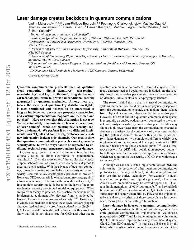
cation, we chose a long-distance satellite QKD prototype op-erating at 532 nm wavelength21 employing Bennett-Brassard1984 (BB84) protocol5. At each time slot, Alice randomlysends one out of four polarizations: horizontal (H), vertical(V), +45◦ (D), or −45◦ (A) using a phase-randomized at-tenuated laser. Bob randomly measures in either horizontal-vertical (HV) or diagonal-antidiagonal (DA) basis, using apolarization-beamsplitter receiver (Fig. 2a). It has been shownin Ref. 16 that an eavesdropper can, in practice, tilt the beamgoing towards Bob by an angle (φ, θ) such that the beammisses, partially or fully, the cores of fibers leading to threedetectors while being relatively well coupled into the coreleading to the fourth detector, as illustrated in Fig. 2a. Thishappens because real-world optical alignments are inherentlyimperfect and manufacturing precision is finite. By sendinglight at different spatial angles, the eavesdropper can havecontrol over Bob’s basis and measurement outcome and stealthe key unnoticed14,16,26. This attack can be prevented by plac-ing a spatial filter or ‘pinhole’ at the focal plane of lensesL1 and L2, as shown in Fig. 2a16. Since the pinhole limitsthe field of view, any light entering at a higher spatial angleis blocked and Eve no longer has access to the target anglesrequired to have control over Bob. As was demonstrated inRef. 16, a pinhole of 25 µm diameter eliminates this side-channel by making the angular efficiency dependence identi-cal between the four detectors (Fig. 3a).
We tested the endurance of this countermeasure againstlaser damage. From a distance of 26.1 m, we shot an 810 nm
collimated laser beam delivering a 10 s pulse of 3.6 W c.w.power at the pinhole inside Bob’s setup. The intensity therewas sufficient to melt the material (13 µm thick stainless steel)and enlarge the hole diameter to ≈ 150 µm. The state ofthe pinhole before and after damage is shown in Fig. 2b, andthe damage process in real time is shown in SupplementaryVideo 1. Although Bob was up and running in photon count-ing mode during the test, none of his other components weredamaged. See Methods for experimental details.
With this larger pinhole opening, it was again possible tosend light at angles that had relatively higher mismatches inefficiency, as shown in Fig. 3b. This enabled a faked-stateattack under realistic conditions of channel loss in 1–15 dBrange with quantum bit error ratio (QBER)< 6.6% (see Meth-ods). Thus laser damage completely neutralizes this counter-measure, and makes this free-space QKD system insecure.
Discussion. The crucial step of the attack, creating theloophole, has thus been experimentally demonstrated for bothsystems tested. After this, building a complete eavesdropperwould be a realistic if time-consuming task27.
Countermeasures to the laser-damage attack may include apassive optical power limiter28, a single-use ‘fuse’ that perma-nently breaks the optical connection if a certain power is ex-ceeded, or battery-powered active monitoring supplementedwith wavelength filtering. Hardware self-characterizationmay be promising29, however to protect from an arbitrarydamage it must monitor a potentially large number of hard-ware parameters. Any countermeasure must be tested in all
3
−1.84−1.84 +1.840
+1.84
0
Attack anglesθ (mrad)
ϕ (m
rad)
ϕ θ−−++
110-1
10-2
10-3
10-5
η
H V AD1
10-2
10-4η
ba V
−1.84−1.84 +1.840
+1.84
0
θ (mrad)
ϕ (m
rad)
ϕ θ−−++
1
10-2
10-4η
10-4 HV
DA
�
��
�
FIG. 3. Efficiency-mismatch side-channel opened after laser damage in free-space QKD system. Each pair of 3D–2D plots showsnormalised photon detection efficiency η in a receiver channel versus illuminating beam angles φ and θ. a, Before laser damage, the angulardependence is essentially identical between the four channels16. Plot for one channel (V) before damage is shown. b, After the laser damage,the four receiver channels H, V, D, A exhibit unequal sensitivity to photons outside the middle area around φ = θ = 0. The last plot showsangular ranges for targeting the four detectors that satisfy conditions for the faked-state attack.
possible illumination regimes. Eve can use a wide range ofwavelengths and optical pulse durations. Optical fiber trans-mits wavelengths from ultraviolet to ∼ 2000 nm, while free-space optics may also be transparent at longer wavelengths.While we have demonstrated c.w. thermal laser damage on thetimescale of seconds, short-pulsed laser radiation may inducedifferent damage mechanisms30. Furthermore, systems can beattacked in both powered and unpowered state (e.g., during anoutage or maintenance). By Kerckhoffs’ principle31, Eve isassumed to predict and know the damage precisely. In prac-tice when attacking installed systems, she may characterizethem by imaging, reflectometry25 and watching public com-munication Alice–Bob while probing their response to attacksporadically, adjusting her attack parameters until they enablefull eavesdropping26. In summary, construction of counter-measures that guarantee security remains an open question.
In this work we have tested two QKD systems and a QCTsystem against laser damage, and compromised the securityof each. Although we have not experimentally tested this,it seems the security parameters, characteristics and assump-tions of any other implementations of quantum communica-tion protocols might also be vulnerable to laser damage. Forexample, in a coherent-one-way QKD scheme32, the front-endcontains an attenuator, coupler, and monitoring p-i-n detec-tor, all of which are potentially vulnerable. Similarly, thereis no guarantee that the measurement-device-independent33
and fully-device-independent34 QKD implementations cannotbe altered by laser damage (potentially breaking the assump-tions of a trusted source in the former and the absence ofinformation-leakage channels in the latter). Any alteration ofcharacteristics might compromise the security either directlyby leading to an attack, or indirectly by shifting some parame-ter in the security proof so it would no longer apply. Since thelaser damage is a new eavesdropping tool that alters a well-characterized system, the community needs to think againhow to ascertain the security proofs against changing secu-rity parameters. We expect that testing against optical attacks
including laser damage will become an obligatory part of se-curity assurance for future quantum communications.
1Barz, S. et al. Demonstration of blind quantum computing.Science 335 303–308 (2012).
2Collins, R. J. et al. Realization of quantum digital signatureswithout the requirement of quantum memory. Phys. Rev.Lett. 113 040502 (2014).
3Pappa, A. et al. Experimental plug and play quantum coinflipping. Nat. Commun. 5 3717 (2014).
4Grice, W. P. et al. Two-party secret key distribution via amodified quantum secret sharing protocol. Opt. Express 237300 (2015).
5Bennett, C. H. & Brassard, G. Quantum Cryptography:Public Key Distribution and Coin Tossing. In Proceedingsof IEEE International Conference on Computers, Systems,and Signal Processing, 175–179 (IEEE Press, New York,Bangalore, India, 1984).
6Lo, H.-K. & Chau, H. F. Unconditional security of quantumkey distribution over arbitrarily long distances. Science 2832050–2056 (1999).
7Gottesman, D., Lo, H.-K., Lutkenhaus, N. & Preskill, J. Se-curity of quantum key distribution with imperfect devices.Quant. Inf. Comp. 4 325–360 (2004).
8Bugge, A. N. et al. Laser damage helps the eavesdropper inquantum cryptography. Phys. Rev. Lett. 112 070503 (2014).
9Singh, S. The Code Book: The Science of Secrecy from An-cient Egypt to Quantum Cryptography (Fourth Estate, Lon-don, 1999).
10Shor, P. W. Polynomial-time algorithms for prime factoriza-tion and discrete logarithms on a quantum computer. SIAMJ. Comput. 26 1484–1509 (1997).
11Bennett, C. H., Bessette, F., Salvail, L., Brassard, G. &Smolin, J. Experimental quantum cryptography. J. Cryp-tology 5 3–28 (1992).
12Makarov, V., Anisimov, A. & Skaar, J. Effects of detectorefficiency mismatch on security of quantum cryptosystems.
4

Phys. Rev. A 74 022313 (2006). Erratum ibid. 78, 019905(2008).
13Qi, B., Fung, C.-H. F., Lo, H.-K. & Ma, X. Time-shift attackin practical quantum cryptosystems. Quant. Inf. Comp. 773–82 (2007).
14Lydersen, L. et al. Hacking commercial quantum cryptogra-phy systems by tailored bright illumination. Nat. Photonics4 686–689 (2010).
15Sun, S.-H., Jiang, M.-S. & Liang, L.-M. PassiveFaraday-mirror attack in a practical two-way quantum-key-distribution system. Phys. Rev. A 83 062331 (2011).
16Sajeed, S. et al. Security loophole in free-space quantumkey distribution due to spatial-mode detector-efficiency mis-match. Phys. Rev. A 91 062301 (2015).
17Fung, C.-H. F., Tamaki, K., Qi, B., Lo, H.-K. & Ma, X.Security proof of quantum key distribution with detectionefficiency mismatch. Quant. Inf. Comp. 9 131–165 (2009).
18National security telecommunications and informationsystems security advisory memorandum (NSTISSAM)TEMPEST/2-95, red/black installation guidance (US Na-tional Security Agency, 1995). Declassified in 2000. http://cryptome.org/tempest-2-95.htm.
19Stucki, D., Gisin, N., Guinnard, O., Ribordy, G. & Zbinden,H. Quantum key distribution over 67 km with a plug&playsystem. New J. Phys. 4 41–41 (2002).
20Clavis2 specification sheet, http://www.idquantique.com/images/stories/PDF/clavis2-quantum-key-distribution/clavis2-specs.pdf, visited 27 July 2015.
21Bourgoin, J.-P. et al. Experimentally simulating quantumkey distribution with ground-to-satellite channel losses andprocessing limitations (manuscript in preparation).
22Sajeed, S. et al. Attacks exploiting deviation of mean photonnumber in quantum key distribution and coin tossing. Phys.Rev. A 91 032326 (2015).
23Erven, C. et al. An experimental implementation of obliv-ious transfer in the noisy storage model. Nat. Commun. 53418 (2014).
24Lunghi, T. et al. Experimental bit commitment based onquantum communication and special relativity. Phys. Rev.Lett. 111 180504 (2013).
25Vakhitov, A., Makarov, V. & Hjelme, D. R. Large pulseattack as a method of conventional optical eavesdropping inquantum cryptography. J. Mod. Opt. 48 2023–2038 (2001).
26Makarov, V. & Hjelme, D. R. Faked states attack on quan-tum cryptosystems. J. Mod. Opt. 52 691–705 (2005).
27Gerhardt, I. et al. Full-field implementation of a perfecteavesdropper on a quantum cryptography system. Nat.Commun. 2 349 (2011).
28Tutt, L. W. & Boggess, T. F. A review of optical limitingmechanisms and devices using organics, fullerenes, semi-conductors and other materials. Prog. Quant. Electr. 17299–338 (1993).
29Lydersen, L., Makarov, V. & Skaar, J. Secure gated de-tection scheme for quantum cryptography. Phys. Rev. A 83032306 (2011).
30Wood, R. M. Laser-Induced Damage of Optical Materials(CRC Press, 2003).
31Kerckhoffs, A. La cryptographie militaire. J. des SciencesMilitaires IX 5–38 (1883).
32Walenta, N. et al. A fast and versatile quantum key distribu-tion system with hardware key distillation and wavelengthmultiplexing. New J. Phys. 16 013047 (2014).
33Lo, H.-K., Curty, M. & Qi, B. Measurement-device-independent quantum key distribution. Phys. Rev. Lett. 108130503 (2012).
34Acın, A., Gisin, N. & Masanes, L. From Bell’s theorem tosecure quantum key distribution. Phys. Rev. Lett. 97 120405(2006).
35Jain, N. et al. Device calibration impacts security of quan-tum key distribution. Phys. Rev. Lett. 107 110501 (2011).
36Stucki, D. et al. Long-term performance of the SwissQuan-tum quantum key distribution network in a field environ-ment. New J. Phys. 13 123001 (2011).
37Sauge, S., Lydersen, L., Anisimov, A., Skaar, J. & Makarov,V. Controlling an actively-quenched single photon detectorwith bright light. Opt. Express 19 23590–23600 (2011).
Acknowledgements. We thank Q. Liu, E. Anisimova andO. Di Matteo for early experimental efforts, S. Todoroki,N. Lutkenhaus, M. Mosca, Y. Zhang and L. Lydersen fordiscussions. This work was supported by the US Officeof Naval Research, Industry Canada, CFI, Ontario MRI,NSERC, Canadian Space Agency, ID Quantique, EuropeanCommission’s FET QICT SIQS project, EMPIR 14IND05MIQC2 project, and CryptoWorks21. We acknowledge usingUniversity of Waterloo’s Quantum NanoFab. P.C. was sup-ported from Thai DPST scholarship. J.-P.B. was supported byFED DEV.
Conflicts of interest. A part of this study was supported andM.L. was employed by ID Quantique. The company has beeninformed prior to this publication, and is developing counter-measures for their affected QKD system. The other authorsdeclare no competing financial interests.
Author contributions. V.M. conceived and led the study.S.K. implemented the fiber-optic experiment. S.S. imple-mented the free-space experiment and contributed to the fiber-optic experiment. P.C. contributed to the free-space experi-ment. M.G. contributed to the fiber-optic experiment. C.M.made minor contributions to the free-space experiment. M.L.provided and supported the fiber-optic QKD system undertest. T.J. and J.-P.B. provided the free-space QKD receiverunder test and contributed to the free-space experiment. R.K.provided the fiber laser facility and co-supervised the fiber-optic experiment. S.S. and V.M. wrote the article, with contri-butions from all authors.
5

METHODS
Laser-damage experiment on fiber-optic system. In our ex-periment, we damaged Dpulse during QKD operation, tryingnot to interrupt it. The system was allowed to start up andproduce a secret key for several QKD cycles, using BB84protocol5. To perform laser damage, we disconnected thechannel for 2–3 min, giving us enough time to apply highpower to Alice, and then reconnected the channel. We triedthis at different points in the QKD operation cycle. Sometimesthe software recovered and resumed QKD, and sometimes itgot stuck in recalibration routines. In the latter case, a manualsoftware restart resumed QKD. Owing to a limited number oftrials, we did not perfect this timing aspect.
We tested a total of 6 photodiode samples. We damagedeach of them by applying high power laser light at Alice’s en-trance. We then used the manufacturer’s factory-calibrationsoftware to measure how much extra signal power (comparedto the pre-calibrated power level) could be injected withouttriggering the alarm22. This quantified the reduction in sensi-tivity due to the damage. Three samples were exposed twiceto a progressively higher power. For example, one sample wasfirst exposed to 0.5 W power at Alice’s entrance that reducedits photosensitivity by 1 dB, then to 0.75 W power that re-duced its photosensitivity by 6 dB. For the other two samplesthese numbers were 0.75W with no change in sensitivity then1.0 W, 1.6 dB (shown in 2nd microphotograph in Fig. 1b);1.0 W, 5 dB then 1.5 W, 5.5 dB (shown in 3rd microphoto-graph in Fig. 1b). For the remaining three samples, 1.7W wasapplied at Alice’s entrance, and Dpulse completely lost photo-sensitivity, becoming electrically either a large resistor (shownin 4th microphotograph in Fig. 1b) or an open circuit. Afterwe were done with each sample, we used the same manufac-turer’s factory-calibration software to pre-calibrate the sensi-tivity of the next undamaged Dpulse sample, following the fac-tory procedure.
No other component in Alice was damaged during these tri-als. We also tested some components separately. FC/PC andFC/APC optical connectors used in Alice and in the channelwithstood 3W c.w., while copies of Alice’s 10:90 fiber beam-splitters (AFW Technologies FOSC-1-15-10-L-1-S-2) with-stood up to 8 W c.w. with no damage.
Figure 4 summarizes a system operation log when it recov-ered automatically after the damage that made the photodiodean open-circuit with no photosensitivity. In the current sys-tem implementation, this represents an ideal outcome for anattacker.
For damaging and component tests, Eve used an erbium-doped fiber amplifier seeded from a 1550.7 nm laser source(EDFA; IPG Photonics ELR-70-1550-LP). She injected 0–2 W c.w. power at Alice’s entrance. The injected power wasmonitored with a 1:99 fiber beamsplitter tap and a power me-ter (Fig. 1a). A manually operated shutter at the output ofEDFA allowed to ramp the power up and down smoothly be-tween 0 and the target level, with tens of milliseconds tran-sition time. The spectral characteristics of EDFA’s built-inseed laser did not precisely match the passband of the BPF atAlice’s entrance (1551.32–1552.12 nm passband at −0.5 dB
Time since system start (min)
Acc
umul
ated
secr
et k
ey (M
bit)
0 10 20 30 40 700
1
2
3
50 60
Disconnection& damage
FIG. 4. Fiber-optic QKD system operation during laser dam-age. The plot shows accumulated secret key amount versus time.Grey bands denote the system performing recalibration routines,white bands denote the quantum bit sending and receiving, and blue(darker) bands denote classical post-processing. All this informationwas extracted from the QKD system log files after the experiment.The band hatched in red denotes the time when the fiber channelAlice–Bob was temporarily disconnected and the laser damage toAlice was done by 1.7 W laser power, resulting in Dpulse becomingan open circuit with no photosensitivity.
level, < 0.7 dB insertion loss; AFW Technologies BPF-1551.72-2-B-1-1). We therefore removed the BPF for theduration of experiment. The BPF was separately tested in-passband using a different EDFA (PriTel LNHPFA-37) with anarrowband seed laser, and passed more than 1 W c.w. withno damage.
The system QKD software (‘QKD Sequence’ application20)set the variable attenuator VOA2 at 2 dB. Thus, 44% of Al-ice’s incoming light impinged Dpulse, while smaller fractionsimpinged Dsync and Dcw. The alarm threshold of Dpulse is cal-ibrated when the system is assembled at the factory, and isnot changed after that22. VOA3 introduced channel loss of1.87 dB, to simulate the effect of ≈9 km long fiber line Alice–Bob.
The QKD system Clavis2 normally operates automaticallyin cycles consisting of sending and receiving quantum statesuntil either the memory buffer is full or photon detection effi-ciency has dropped significantly. It then uses the classical linkAlice–Bob to post-process the detected data and distill the se-cret key11. Each cycle takes several minutes. If the last QKDcycle was interrupted because the detection efficiency was toolow, or the key distillation failed, the system returns to start-up routines such as timing recalibration35 before it resumessending quantum states. This happens often in normal op-eration, because of naturally occurring drift of hardware andchannel parameters. The software generally tries to recoverautomatically from various error conditions, to provide long-term unattended operation36.
Predicted attacks on fiber-optic system with damagedpulse-energy-monitoring photodiode. As modeled inRef. 22, for BB84 QKD protocol Eve can eavesdrop partialor full key information using today’s best photonics technolo-gies when the sensitivity of Dpulse has dropped by 4.3–5.6 dB,given that communication channel loss Alice–Bob is in a 1–7 dB range. (This corresponds to a multiplication factor x inthe range of 2.7–3.6, see Fig. 11 in Ref. 22.) If we assumethat Eve’s equipment is only limited by the laws of quantummechanics, then she can extract the full key information after
6

only 0.4–0.8 dB reduction in sensitivity (x of 1.1–1.2). Simi-larly, for QCT with a dishonest Bob only limited by the quan-tum mechanics, all the quantum advantages of the protocolare eliminated if sensitivity reduction of 2.6 dB is obtained inAlice (x = 1.805), for a 15 km long communication channel.For a 10 dB sensitivity reduction, Bob’s cheating probabilityapproaches unity22. Since we have surpassed the above sensi-tivity reduction thresholds in our laser damage experiment, weconsider the security of both QKD and QCT implementationcompromised.
Laser-damage experiment on free-space QKD system. Inorder to neutralize the effect of the pinhole and reproduce theside-channel of spatial-mode detector-efficiency mismatch,our experiment consisted of three steps. Firstly, we performedscanning to certify that the system is secure against this side-channel. Secondly, we laser-damaged the pinhole to openthe side-channel. Finally, we performed scanning again todemonstrate that the system’s security has been compromised.In all three steps, Eve was placed at a distance of 26.1 m awayfrom Bob and the steps were performed in sequence withoutmaking any interactions with Bob.
The first step involved changing the outgoing beam’s angle(φ, θ) emitted from Eve’s scanning setup shown in Fig. 2a,then recording the corresponding count rate at all four detec-tors in Bob. This step is identical to that in Ref. 16. Thescanning result is shown in Fig. 3a, where a pair of 3D–2Dplots shows the normalized photon detection efficiency in onereceiver channel versus the illuminating beam angles φ andθ. With the pinhole in place, the angular dependence of ef-ficiency is essentially identical between the four channels,hence only a plot for channel V is shown. No measurableamount of efficiency mismatch was found and no attack an-gles existed16.
Then as the second step, Eve’s scanning setup was replacedwith the damaging setup. The latter contained a 810 nmlaser diode (Jenoptik JOLD-30-FC-12) pumped by a current-stabilized power supply and connected to 200 µm core diam-eter multimode fiber. It provided continuously adjustable 0 to30 W c.w. power into the fiber. An almost-collimated free-space beam was subsequently formed by a plano-convex lensL5 (Thorlabs LA1131-B; Fig. 2a). The beam’s intensity wasnearly uniformly distributed across Bob’s L1 (50 mm diam-eter achromatic doublet, Thorlabs AC508-250-A), with lessthan ±10% intensity fluctuation across Bob’s input aperture.Transmission of L1 was about 82%, owing to its antireflectioncoating being designed for a different wavelength band. Inthe test detailed here, the power delivered at the pinhole planewas 3.6 W, sufficient to reliably produce a hole of ≈150 µmdiameter in less than 10 s in a standard stainless-steel foil pin-hole (Thorlabs P25S). We also tested that power decreased to2.0 W still produced a hole. No other component in Bob wasdamaged during the tests. Bob’s lenses L4 received ∼ 1 µWpower each, and single-photon detectors only received on theorder of a few nW each, mainly owing to the presence ofBPF after the pinhole. The BPF was used by Bob to increasethe signal-to-noise ratio during QKD by heavily attenuatingall light outside the 531–533 nm passband (it consisted oftwo stacked filters, Thorlabs FESH0700 followed by Semrock
LL01-532-12-5)21. While the damaging beam was on, the de-tectors counted at their saturation rate of ∼35MHz, which didnot look abnormal to Bob as this sometimes occurs naturallyowing to atmospheric conditions (during sunset, sunrise, fog).We remark that this type of detector usually survives tens ofmW for a short time8,37. Even if we had to use a wavelengthwithin the BPF’s passband, detector exposure to higher powercould likely be avoided by shaping Eve’s damaging beam.
After the damage, as the third step we replaced the damag-ing setup with the scanning setup again, and performed the fi-nal scanning of Bob’s receiver with the damaged pinhole. Theresults are shown in Fig. 3b. Now, the four receiver channelsH, V, D, A exhibited unequal sensitivity to photons outside themiddle area around φ = θ = 0. These efficiency plots weredifferent from those measured in Ref. 16 without the pinhole,because of extra scattering at the edges of our laser-enlargedpinhole.
Predicted attack on free-space QKD system with damagedpinhole. We model a practical faked-state attack as describedin Ref. 16. We assume a part of Eve is situated outside Al-ice and measures the quantum states coming out. Then, an-other part of her regenerates the measured quantum states asattenuated coherent pulses and sends them to Bob, tilting herbeam at an angle such that it has a relatively higher probabil-ity of being detected by the desired detector. Eve has informa-tion about Bob’s receiver characteristics after the laser dam-age, and only uses devices available in today’s technology16.For example, let’s assume Eve sends a horizontally polarizedlight pulse. In this case, she should choose her tilt angle(φ, θ) from a subset H selected in such a way that the ef-ficiency ηh(H) of Bob’s horizontal channel in H is as highas possible, in order to maximize mutual information Eve–Bob. On the other hand, if Bob measures in the opposite(DA) basis, the detection probabilities in the D and A chan-nels ηd(H) and ηa(H) should be as low as possible, to min-imize QBER. Thus, to find attack angles for the horizontallypolarized light, we choose H that satisfies ηh(H) ≥ 0.6 and
0 5 10 15 20 250
5
10
15
20
Channel loss (dB)
QB
ER
(%)
FIG. 5. Modeled QBER observed by Bob in free-space QKD sys-tem. The dotted curve shows QBER without Eve. At lower channelloss, the QBER is due to imperfect fidelity, while at higher channelloss Bob’s detector background counts become the dominant contri-bution. The lower solid curve (blue) shows QBER under our attackwhen only Bob’s sifted key rate is kept the same as before the at-tack. The upper solid curve (red) additionally keeps the same siftedkey rates conditioned on each polarization sent by Alice, which moreclosely mimics a realistic system operation (see Ref. 16 for details).
7

δ(H) = min{ηh(H)
ηd(H), ηh(H)
ηa(H)
}≥ 100. Similarly, for V, D
and A polarized pulses, we choose attack angles that satisfyηv(V ) ≥ 0.03, δ(V ) ≥ 4.5; ηd(D) ≥ 0.6, δ(D) ≥ 120;ηa(A) ≥ 0.2, δ(A) ≥ 22. These subsets of angles are shownin the rightmost plot in Fig. 3b. Note that the thresholds ηand δ used here are not optimal and have been picked manu-ally. However, they satisfy the required conditions to success-fully perform the faked-state attack with a resultant QBER≤ 6.6% in 1–15 dB channel loss range, as shown in Fig. 5.In the simulation, we assumed that Alice–Bob and Alice–Evefidelity F = 0.983116,21, while Eve–Bob experimentally mea-sured F = 0.9904. All other assumptions were the same as inRef. 16.
Additional considerations in experiment on fiber-opticsystem. When we began testing the system components forlaser damage, the synchronization detector Dsync initially pre-sented an obstacle. This detector was based on an opticalreceiver module (Fujitsu FRM5W232BS) incorporating anavalanche photodiode biased below breakdown at > 30 V,providing an avalanche multiplication factor ≈6. It only tookabout 6 mW of optical power at the photodiode (translatingto about 0.15 W at Alice’s entrance) to die. It stopped pro-viding the synchronization signal for Alice and thus broke thesystem. After an investigation, it turned out that the energythat killed it was chiefly provided by its high-voltage electri-cal bias circuit and not the optical signal. The bias circuitwas based on a specialised integrated circuit with overcurrentprotection (Maxim Integrated MAX1932ETC) followed by anLC low-pass filter with inductor L = 330 µH and capacitorC = 0.47 µF. If the optical power is applied suddenly, withsub-nanosecond rise time, it momentarily induces a large pho-tocurrent supplied from C that destroys the avalanche photo-diode. If, however, the optical power is applied gradually,with millisecond rise time, C discharges slowly and then therelatively slow overcurrent protection reacts in the integratedcircuit, lowers the bias voltage and saves the photodiode. Wethus added a manual shutter to the EDFA to make the dam-aging power rise from zero slowly, allowing Dsync to easilywithstand the optical power used in our attack while beingelectrically powered up. Another solution could be to damagethe system when it is without electrical power. It can also besaid that we could choose to selectively damage one of twocomponents in Alice, albeit one of them bricking the system.
We ran our damage tests with VOA2 (OZ Optics DD-600-11-1300/1550-9/125-S-40-3S3S-1-1-485:1-5-MC/IIC) set at2 dB, because this is what the manufacturer’s QKD softwareavailable for the research system Clavis2 set it at. The supportof the pulse-energy-monitoring countermeasure was not im-plemented in this software22. In contrast, the manufacturer’sfactory-calibration software supported it fully and set VOA2between 2 and ≈15 dB, complementary to the channel loss, inorder to maintain constant power at the three Alice’s detectorsDpulse, Dsync, and Dcw. The higher settings of VOA2 wouldrequire more laser power to damage Dpulse. However, Dpulsecould also be damaged during the system start-up time, whenit sends the homing command to VOA2. The homing com-mand causes it to traverse its lowest attenuation values for a
few seconds, likely being sufficient for Eve to do the damageat already demonstrated power levels.
Supplementary Video 1. Real-time video recordingof laser damage to the spatial filter inside Bob’ssetup. Download the video at http://vad1.com/pinhole-laser-damage-20140825.wmv (Win-dows Media Video, 14.4 MiB) or http://vad1.com/pinhole-laser-damage-20140825.ppsx (Power-Point Show, 17.0 MiB). The video shows the spatial filter(Thorlabs P20S) illuminated by 3.6 W c.w. 810 nm laserbeam for 10 s, focused in a spot much wider than the originalpinhole diameter of 20 µm. This is a filter sample with aslightly smaller original pinhole diameter than the one usedto obtain efficiency mismatch data in this article and shownin Fig. 2b. The samples were otherwise of the same type anddamaged under the same conditions. The video was taken viaa mirror lowered inside Bob’s setup. The pinhole plane wasimaged from the front side at an angle slightly off normal,in order for the mirror not to obstruct the damaging beam.Canon MP-E 65 mm lens was used at 2.8× magnificationand f/16 lens aperture (f/60 effective aperture), with CanonEOS 7D camera body. The pinhole was brightly lit sidewayswith a fiber-optic illuminator bundle, in order to bring updetail. During the laser exposure, the steel foil can be seendeforming from heat, popping out of focus and apparentlyshifting laterally in the image; however the lateral shift isan artefact of the camera’s angle of view being off-normal.After the laser is switched off, the foil cools and returns to theoriginal position, now with about 150 µm diameter hole in it.Sound was added later for an artistic effect.
8


![Backdoors et rootkits_avancees_[slides]](https://static.fdocuments.us/doc/165x107/58eff1d91a28ab5c4f8b4615/backdoors-et-rootkitsavanceesslides.jpg)