Laser Beam Machining
38
Dr. Lotfi K. Gaafar 2002 Maulana Azad National Institute Of Technology “ Laser Beam Machining” Presented By : Akash Saxena 091116280 Suyash Porwal 091116283 Herdesh Sharma 091116284 Priyanshu Verma 091116285 Akash Sangwan 091116286 Apanshu Goel 091116288
-
Upload
ayushigoyal -
Category
Documents
-
view
37 -
download
1
Transcript of Laser Beam Machining

Maulana Azad National Institute
Of Technology
“Laser Beam Machining”Presented By : Akash Saxena 091116280 Suyash Porwal 091116283 Herdesh Sharma 091116284 Priyanshu Verma 091116285 Akash Sangwan 091116286 Apanshu Goel 091116288
Outline
Laser Beam Machining Material Removal Mechanism of LBM Processes:
Cutting Drilling Welding Rapid Prototyping Other: Precise Measurement, Heat Treatment, Scribing
Parameters Affecting LBM General Advantages and Disadvantages Economics Safety measures Useful Links and References
Laser Technology
Thermal nontraditional machining process High energy laser beam melts and vaporizes
material Beam:
Continuous Pulse
Examples of lasing materials: Co2
YAG

Schematic Diagram of LBM
Principle and Working
The principle is that under proper conditions light energy of a particular frequency is utilised to stimulate the electrons in an atom to emit additional light with exactly the same characteristics of the original light source.
The laser beam is focused with the help of lens and workpiece is placed near the focal point of the lens. A short pulse of laser melts and vaporises the material. The explosive escape of the vaporised material helps in removing most of the molten metal from the hole as tiny droplets. Any of the molten metal not removed will be resolidified along the walls of the hole.

Laser Technology
Important physical parameters of workpiece materials: Reflectivity Thermal conductivity Specific heat Latent heat
Features of laser beam: High power Monochromatic Coherent Non-contact

Material Removal Mechanism

As presented in Fig. 5, the unreflected light is absorbed, thus heating the surface of the workpiece.
On sufficient heat the workpiece starts to melt and evaporates.
The physics of laser machining is very complex due mainly to scattering and reflection losses at the machined surface. Additionally, heat diffusion into the bulk material causes phase change, melting, and/or vaporization.
Depending on the power density and time of beam interaction, the mechanism progresses from one of heat absorption and conduction to one of melting and then vaporization.
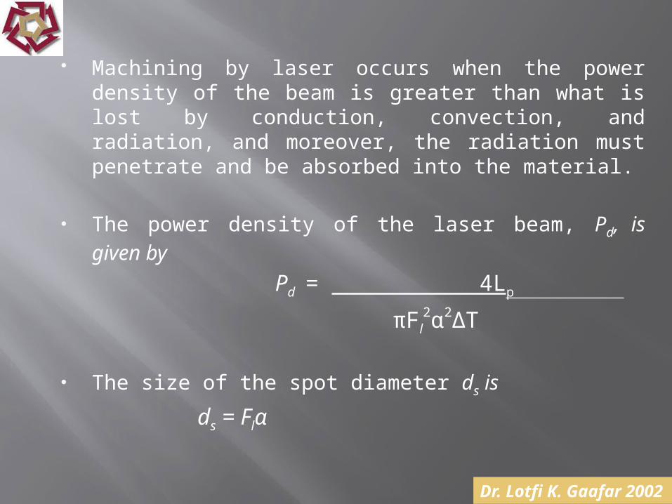
Machining by laser occurs when the power density of the beam is greater than what is lost by conduction, convection, and radiation, and moreover, the radiation must penetrate and be absorbed into the material.
The power density of the laser beam, Pd, is given by
Pd = 4Lp
πFl2α2∆T
The size of the spot diameter ds is
ds = Flα

The machining rate φ (mm/min) can be described as follows:
φ= ClLP
Ev Abh
Where Ab = area of laser beam at focal point, mm2
Ab= π (Flα)2
4
Therefore, φ= 4ClLP
π Ev (Flα)2 h

The volumetric removal rate (VRR) (mm3/min) can be calculated as follows:
VRR= ClLP
Ev h
Where, Pd = power density, W/cm2
Lp = laser power, W
Fl = focal length of lens, cm
ΔT = pulse duration of laser, s α = beam divergence, rad Cl = constant depending on the material and
conversion efficiency
Ev = vaporization energy of the material, W/mm3
Ab = area of laser beam at focal point, mm2
h = thickness of material, mm ds = spot size diameter, mm

Processes
Applications of Laser in manufacturing

Processes: Cutting
Cutting starts by drilling a hole then moving the beam in a programmed path.
A stream of assist gas* is used to:
blow the molten metal
Cool workpiece Minimize heat
affected zone
Laser Processing System
Processes: Cutting
Cutting Speed depends on: Material Thickness
Range of thickness: Metals up to 0.5in Nonmetal up to 1in

Processes: Cutting
Applications
Height following Laser nozzleExamples of laser cutting using pulsed CO2 Laser
Processes: Cutting
Advantages: Narrow kerf and heat affected zone No post-cut finishing is required Economic alternative for materials that are
difficult to cut by conventional methods Narrow slots Closely spaced patterns Does not require smooth surface

Processes: Drilling
Repeated pulsed laser beams Hole diameter depends on the material
thickness Drill micro-holes in metals as thick as 0.1in L:D ratio: 10:1 Cutting Speed decreases depth increases but:
Generates irregular holes Recast layer increases Heat affected zone increases
Process: Drilling
Applications: Bleeder holes for fuel pump covers Drilling holes in delicate medical
materials Drilling holes in small polymer tubes Drills tiny holes in turbine blades of jet
engine

Processes: Drilling
Advantages: Burr free holes Eliminates drill breakage and wear Drills in difficult to access areas, curved surfaces
and parts incased in glass Drills holes of almost any shape High quality and precision holes Close tolerances
Limitations: Holes up to 1” deep in plastics and ferrous metals,
and 0.125” in reflective materials.
Processes: Welding
Could be used with or without filler Solidifies quickly Filler material is used if gap is large Can be used to produce deep penetration welds Effective with thin workpiece

Processes: Welding
Applications Razor blades Electronic circuits
Razor blades are spot welded using laser

Processes: Welding
Advantages: Does not require vacuum Better quality of weld Beam easily shaped, directed, and focused No direct contact is necessary to produce a weld Encapsulated and inaccessible areas can be
welded Can be made with access to only one side of
joint Increase speed and strength of welding Produces maximum penetration and minimum
distortion in the material
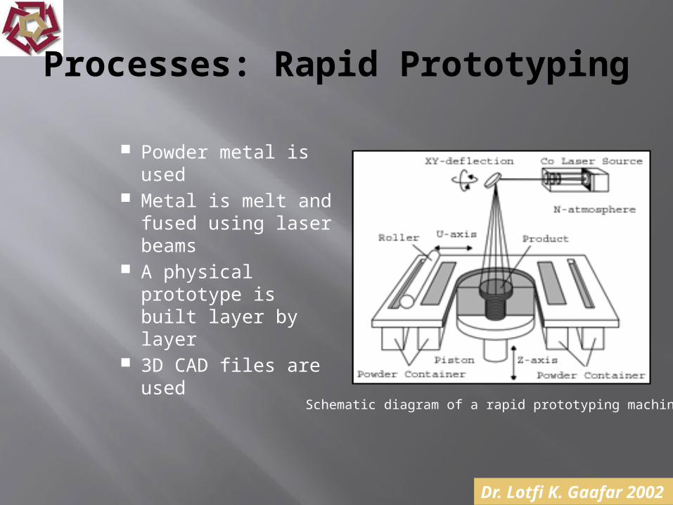
Processes: Rapid Prototyping
Powder metal is used Metal is melt and
fused using laser beams
A physical prototype is built layer by layer
3D CAD files are used
Schematic diagram of a rapid prototyping machine

Processes: Rapid Prototyping
Applications:
Models created by rapid prototyping

Processes: Rapid Prototyping
Advantages:
Speeds up the design and manufacturing process
Reduces product development cost Allows for instant feedback to design
engineers Allows for design corrections at an early
stage The model is used in pre-production planning
and tool design

Processes: Rapid Prototyping
Disadvantages:
The generated model has shrinkage cracks The model has high hardness, which
makes it brittle Thick walled structures can’t be built up
very well

Processes: Measurements
Uses Helium-Neon laser beam To align and calibrate machine tools Useful in Large assembly jigs Non-contact: used to inspect hot rolled
material

Processes: Heat Treatment
Produces hardened surfaces
For wide variety of geometries
Can work on limited area Produces little distortion
Cam Part
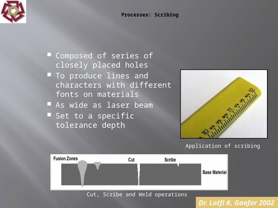
Processes: Scribing
Composed of series of closely placed holes
To produce lines and characters with different fonts on materials
As wide as laser beam Set to a specific tolerance
depth
Cut, Scribe and Weld operations
Application of scribing

Parameters Affecting LBM
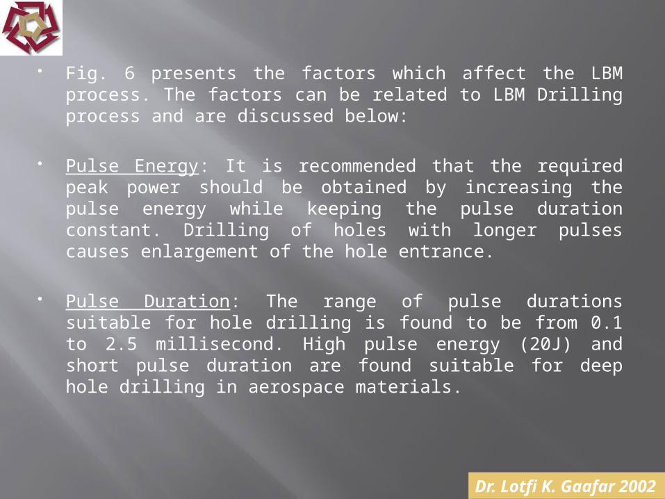
Fig. 6 presents the factors which affect the LBM process. The factors can be related to LBM Drilling process and are discussed below:
Pulse Energy: It is recommended that the required peak power should be obtained by increasing the pulse energy while keeping the pulse duration constant. Drilling of holes with longer pulses causes enlargement of the hole entrance.
Pulse Duration: The range of pulse durations suitable for hole drilling is found to be from 0.1 to 2.5 millisecond. High pulse energy (20J) and short pulse duration are found suitable for deep hole drilling in aerospace materials.

Assist Gases: The gas jet is normally directed with the laser beam into the interaction region to remove the molten material from the machining region and obtain a clean cut. Assist gases also shield the lens from the expelled material by setting up a high-pressure barrier at the nozzle opening. Pure oxygen causes rapid oxidation and exothermic reactions, causing better process efficiency. The selection of air, oxygen, or an inert gas depends on the workpiece material and thickness.
Material Properties and Environment: These include the surface characteristics such as reflectivity and absorption coefficient of the bulk material. Additionally, thermal conductivity and diffusivity, density, specific heat, and latent heat are also considered.

General Advantages
Operates in fully automated environment Minimum heat affected zone compared to other
thermal processes Clean Small clamping force is applied Can be used with metals, nonmetals, and
composites Excellent surface quality Minimum thermal stresses on the material No tooling required

General Disadvantages
Requires specially trained operators Not for mass metal removal processes Requires greater control of joint tolerances Expensive equipment Consumes much energy

Economics
Expensive equipment Requires skilled operators
Compensated by: Fast material removal rate (0.5-7.5m/min) high
production rates Finishing costs are eliminated Can be automated reducing operational costs*
Safety Measures
Lasers can burn and blind: Eyes and skin should be protected from scattered
beams Even low powers can cause damage to retina
Operator should wear gas masks to protect against generated fumes
References
Advanced Machining Processes By Hassan Abdel-Gawad El-Hofy
Non Conventional Machining By P.K. Mishra