LaSalle, Unit 2 Cycle 10 Core Operating Limits Report (COLR).
25
Exekrn,. Exelon Generation Company, LLC www exeloncorp coM N ucl e ar LaSalle County Station 2601 North 21' Road Marseilles, IL 61341-9757 March 28, 2003 United States Nuclear Regulatory Commission Attention: Document Control Desk Washington, D.C. 20555 LaSalle County Station, Unit 2 Facility Operating License No. NPF-18 NRC Docket No. 50-374 Subject: Unit 2 Cycle 10 Core Operating Limits Report (COLR) The purpose of this letter is to advise you of Exelon Generation Company, LLC, review and approval of the LaSalle County Station Unit 2 Cycle 10 reload under the provisions of 10 CFR 50.59, "Changes, tests and experiments," and to transmit the Core Operating Limits Report (COLR) for Cycle 10. This report is being submitted consistent with Generic Letter 88-16, "Removal of Cycle-Specific Parameter Limits From Technical Specifications" and in accordance with LaSalle County Station Technical Specification 5.6.5.d. The reload licensing analyses performed for Cycle 10 utilized NRC approved methodologies. The Unit 2 Cycle 10 core, which consists of NRC approved fuel designs developed by Framatome (formerly Siemens Power Corporation), was designed to operate within approved fuel design criteria provided in the Technical Specifications and related bases. The core operating characteristics are bounded by Updated Final Safety Analysis Report allowable limits. LaSalle County Station has performed a detailed review of the relevant reload licensing documents and the associated bases and references. Based on that review, the COLR was subjected to the 10 CFR 50.59 review process. The review process concluded that the reload does not require prior NRC review and approval. Should you have any questions concerning this submittal, please contact Mr. Glen Kaegi, Regulatory Assurance Manager, at (815) 415-2800. Respectfully, George P. Barnes Site Vice President LaSalle County Station Attachment AooJ cc: Regional Administrator - NRC Region IlIl NRC Senior Resident Inspector - LaSalle County Station
Transcript of LaSalle, Unit 2 Cycle 10 Core Operating Limits Report (COLR).

Exekrn,.Exelon Generation Company, LLC www exeloncorp coM N ucl e arLaSalle County Station2601 North 21' RoadMarseilles, IL 61341-9757
March 28, 2003
United States Nuclear Regulatory CommissionAttention: Document Control DeskWashington, D.C. 20555
LaSalle County Station, Unit 2Facility Operating License No. NPF-18NRC Docket No. 50-374
Subject: Unit 2 Cycle 10 Core Operating Limits Report (COLR)
The purpose of this letter is to advise you of Exelon Generation Company, LLC,review and approval of the LaSalle County Station Unit 2 Cycle 10 reload under theprovisions of 10 CFR 50.59, "Changes, tests and experiments," and to transmit theCore Operating Limits Report (COLR) for Cycle 10. This report is being submittedconsistent with Generic Letter 88-16, "Removal of Cycle-Specific Parameter LimitsFrom Technical Specifications" and in accordance with LaSalle County StationTechnical Specification 5.6.5.d.
The reload licensing analyses performed for Cycle 10 utilized NRC approvedmethodologies. The Unit 2 Cycle 10 core, which consists of NRC approved fueldesigns developed by Framatome (formerly Siemens Power Corporation), wasdesigned to operate within approved fuel design criteria provided in the TechnicalSpecifications and related bases. The core operating characteristics are boundedby Updated Final Safety Analysis Report allowable limits.
LaSalle County Station has performed a detailed review of the relevant reloadlicensing documents and the associated bases and references. Based on thatreview, the COLR was subjected to the 10 CFR 50.59 review process. The reviewprocess concluded that the reload does not require prior NRC review and approval.
Should you have any questions concerning this submittal, please contact Mr. GlenKaegi, Regulatory Assurance Manager, at (815) 415-2800.
Respectfully,
George P. BarnesSite Vice PresidentLaSalle County Station
Attachment AooJcc: Regional Administrator - NRC Region IlIl
NRC Senior Resident Inspector - LaSalle County Station

Technical Requirements Manual - Appendix JL2C10 Core Operating Limits Report
Section 1
Core Operating Limits Report
for
LaSalle Unit 2 Cycle 1 0

Technical Requirements Manual - Appendix J
Technical Requirements Manual - Appendix JL2C10 Core Operating Limits Report
Issuance of Changes Summary
LaSalle Unit 2 Cycle 10 il Revision 0

Technical Requirements Manual - Appendix JL2C10 Core Operating Limits Report
Table of Contents
References.................. .............................. ........... ..................................................... iv
1. Average Planar Linear Heat Generation Rate (3.2.1) .1-1
1.1 Technical Specification Reference .1-11.2 Description. 1-1
2. Minimum Critical Power Ratio (3.2.2) .2-1
2 1 Technical Specification Reference .2-12.2 Description .2-1
3. Linear Heat Generation Rate (3.2.3) .3-1
3.1 Technical Specification Reference .3-13 2 Description .3-1
4. Control Rod Withdrawal Block Instrumentation (3.3.2.1) .4-1
4 1 Technical Specification Reference .4-14.2 Description .4-1
5. Traversing In-Core Probe System (3.2.1, 3.2.2, 3.2.3) .5-1
5.1 Technical Specification Reference .5-15.2 Description .5-15 3 Bases .5-1
6. Allowed Modes of Operation (B 3.2.2, B 3.2.3) .6-1
7. Methodology (5.6.5) .7-1
LaSalle Unit 2 Cycle 10 iii Revision 0
Technical Requirements Manual - Appendix JL2C10 Core Operating Limits Report
References
1. Exelon Generation Company, LLC, Docket No. 50-374 LaSalle County Station, Unit 2, FacilityOperating License, License No. NPF-18.
2. Letter from D. M. Crutchfield to All Power Reactor Licensees and Applicants, Generic Letter88-16; Concerning the Removal of Cycle-Specific Parameter Limits from Tech Specs, October 3,1988.
3 EMF-2830 Revision 0, 'LaSalle Unit 2 Cycle 10 Reload Analysis," Framatome ANP, Inc, January2003.
4. Letter from A. Giancatarino to J. Nugent, OLaSalle Unit 1 and Unit 2 Rod Block Monitor COLRSetpoint Change," NFM.MW:01-0106, April 3, 2001.
5. Letter from D. Garber to R. Chin, "POWERPLEX-Il CMSS Startup Testing", DEG:00.254,December 5, 2000.
6. Letter from D. Garber to R. Chin "POWERPLEX-Il CMSS Startup Testing", DEG:00:256,December 6, 2000.
7. Letter from J.H. Riddle to R. Chin 'TIP Symmetry Testing", JHR:97:021, January 20, 1997 andletter from D.Garber to R. Chin "TIP Symmetry Testing", DEG:99.085, March 23, 1999.
8. EMF-2700 Revision 0, "LaSalle Unit 2 Cycle 10 Principal Transient Analysis Parameters," June2002.
9. "Transient Analysis Evaluation for LaSalle 3 TCV Operation at Power Uprate and MELLLAConditions," NFM:BSA-00-025, R.W. Tsai to D. Bost, April 13, 2000.
10 Letter from A W. Will to F. W. Trikur, "Operation at LaSalle Units I and 2 with One MSIV Out ofService", AWW:03 005, January 15, 2003.
11. 'LaSalle Units 1 and 2 Operation with One TSV OOS - Update Nuclear Fuels Memo NF-MW.02-0431," NF-MW.03-007, Carlos de la Hoz to Kirk Peterman, January 9, 2003.
12. LaSalle County Station Power Uprate Project, Task 201: Reactor Power/Flow Map, GE-NE-A1300384-07-01, Revision 1, September 1999.
13. "Operation with a Pressure Regulator Out of Service at LaSalle," NF-MW:03-0063, Carlos de laHoz to Kirk Peterman, February 7, 2003.
LaSalle Unit 2 Cycle 10 iv Revision 0

Technical Requirements Manual - Appendix JL2C10 Core Operating Limits Report
1. Average Planar Linear Heat Generation Rate (3.2.1)
1.1 Technical Specification Reference
Section 3.2 1.
1.2 Descrintion
Tables 1-1 and 1-2 are used to determine the maximum average planar linear heatgeneration rate (MAPLHGR) limit for each fuel type. Limits given in Tables I-1 and 1-2are for Dual Reactor Recirculation Loop Operation.
For Single Reactor Recirculation Loop Operation (SLO), the MAPLHGR limits given inTables 1-1 and 1-2 must be multiplied by a SLO MAPLHGR multiplier. The SLOMAPLHGR multiplier forATRIUM-10 and ATRIUM-9B fuel is 0.90 (Reference 3 Page7-1).
Table 1-1Maximum Average Planar Linear Heat Generation Rate
(MAPLHGR) for ATRIUM-10 FuelAl 0-4025B-1 5GV80-1 0GMAl 0-3982B-1 5GV80-1 0GM
A10-1786B-OGV-100M(Bundle types 20, 21 and 22)
(Reference 3 Section 7 2.1)
Average Planar Exposure MAPLHGR(GWdIMT) (kW/ft)
0.0 12.5150 12.555 0 9.164.0 7.6
Table 1-2Maximum Average Planar Linear Heat Generation Rate
(MAPLHGR) for ATRIUM-9B FuelA9-381 B-i3GZ7-80MA9-3843B-1 1 GZ6-80M
A9-391 B-14G8.0-100MA9-41 GB-1 9G8.0-1 0GMA9-383B-1 6G8.0-1 0GMA9-396B-12GZ-100M
(Bundle types 14, 15, 16, 17, 18 and 19)(Reference 3 Section 7.2 1)
Planar Average Exposure MAPLHGR(GWd/MT) (kW/ft)
0.0 13.520.0 13564.3 9.07
LaSalle Unit 2 Cycle 10 1-1 Revision 0

Technical Requirements Manual - Appendix JL2C10 Core Operating Limits Report
2. Minimum Critical Power Ratio (3.2.2)
2.1 Technical Specification Reference
Section 3.2.2.
2.2 Description
Limits provided in this section are only valid up to the first sequence exchange (deep-shallow swap) for the cycle, due to potential Control Blade History (CBH) impacts whichwere not determined as part of the original Cycle 10 licensing analyses. A revision tothis document to account for any potential CBH impact will be issued at a future date,prior to the first sequence exchange for Cycle 10.
TIP Symmetry Chi-squared testing shall be performed prior to reaching a cycleexposure of 500 MWd/MT to validate the MCPR calculation.
2.2.1 Manual Flow Control MCPR Limits
The Operating Limit MCPR (OLMCPR) is determined from either section2.2.1.1 or 2 2.1.2, whichever is greater at any given power and flow condition.
2 2.1.1 Power-Dependent MCPR
The power-dependent MCPR value, MCPRp, is determined fromTables 2-1 through 24, and is dependent on fuel type and scramspeed, in addition to power level Table 2-1 or 2-2 is applicable toATRIUM-1 0 fuel and Table 2-3 or 24 is applicable to ATRIUM-9B fuel
2.2.1.2 Flow-Dependent MCPR
The flow dependent MCPR value, MCPRF, is determined from Table 2-5 for all fuel types.
2.2.2 Automatic Flow Control MCPR Limits
Automatic Flow Control is not allowed because MCPR Limits are not provided.
2.2.3 Nominal Scram Speeds
To utilize the MCPR limits for Nominal Scram Speeds (NSS), the core averagescram speed insertion time must be equal to or less than the following values(Reference 8 Section 7.7).
Notch Position Time 145 0.38039 0.68025 1.68005 2.680
LaSalle Unit 2 Cycle 10 2-1 Revision 0

Technical Requirements Manual - Appendix JL2C10 Core Operating Limits Report
Table 2-1MCPRp for ATRIUM-10 Fuel
BOC - First Cycle-10 Sequence ExchangeNominal Scram Speeds (NSS)
(Reference 3 Table 5.1)
Core Thermal Power (% of rated)EOOS Combination 0 25 25(25.01) 60 100
MCPRp
Base Case Operation 2 70 2 20 1.98 1 45 1 40
Single Loop Operation (SLO) 2.71 2.21 1 99 1 46 1 41
* Values are interpolated between relevant power levels.* For thermal limit monitoring at greater than 100% core thermal power, the 100% core
thermal power MCPRp should be applied.* Allowable EOOS conditions are listed in Section 6.
LaSalle Unit 2 Cycle 10 2-2 Revision 0

Technical Requirements Manual - Appendix JL2CIO Core Operating Limits Report
Table 2-2MCPRp for ATRIUM-10 Fuel
BOC - First Cycle-1 0 Sequence ExchangeTechnical Specification Scram Speeds (TSSS)
(Reference 3 Table 5 2)
Core Thermal Power (% of rated)0 | 25 | 25(25.01) | 60 | 80 | 80(80.01) | 100EOOS Combination
MCPRp
Base Case Operation 2.70 2 20 2 05 1 48
FHOOS Only 2.92 2 42 2 42 1 60
EOOS Case 1 2 92 2 42 2.42 1 60
EOOS Case 2 2 92 2 42 2.42
Single Loop Operation (SLO) 2 71 2.21 2 06 1 49
SLO with FHOOS Only 2 93 2 43 2 43 1 61
i 52 _ 48A
1 43
1 53 1 49
SLO with EOOS Case I 2 93 2 43 2 43
SLO with EOOS Case 2 j 2.93 2.43 J 2 43 1.73
* Values are interpolated between relevant power levels.* For thermal limit monitoring at greater than 100% core thermal power, the 100% core thermal
power MCPRp should be applied.* Allowable EOOS conditions are listed in Section 6.
LaSalle Unit 2 Cycle 10 2-3 Revision 0

Technical Requirements Manual - Appendix JL2C10 Core Operating Limits Report
Table 2-3MCPRp for ATRIUM-9B Fuel
BOC - First Cycle-10 Sequence ExchangeNominal Scram Speeds (NSS)
(Reference 3 Table 5 1)
Core Thermal Power (% of rated)EOOS Combination 0 25 25(25.01) 60 100
MCPRp
Base Case Operation 2 70 2 20 1 91 1 45 1 40
Single Loop Operation (SLO) 2.71 2 21 1.92 1.46 1 41
* Values are interpolated between relevant power levels.* For thermal limit monitoring at greater than 100% core thermal power, the 100% core
thermal power MCPRp should be applied.* Allowable EOOS conditions are listed in Section 6.
LaSalle Unit 2 Cycle 10 2-4 Revision 0
Technical Requirements Manual - Appendix JL2C10 Core Operating Limits Report
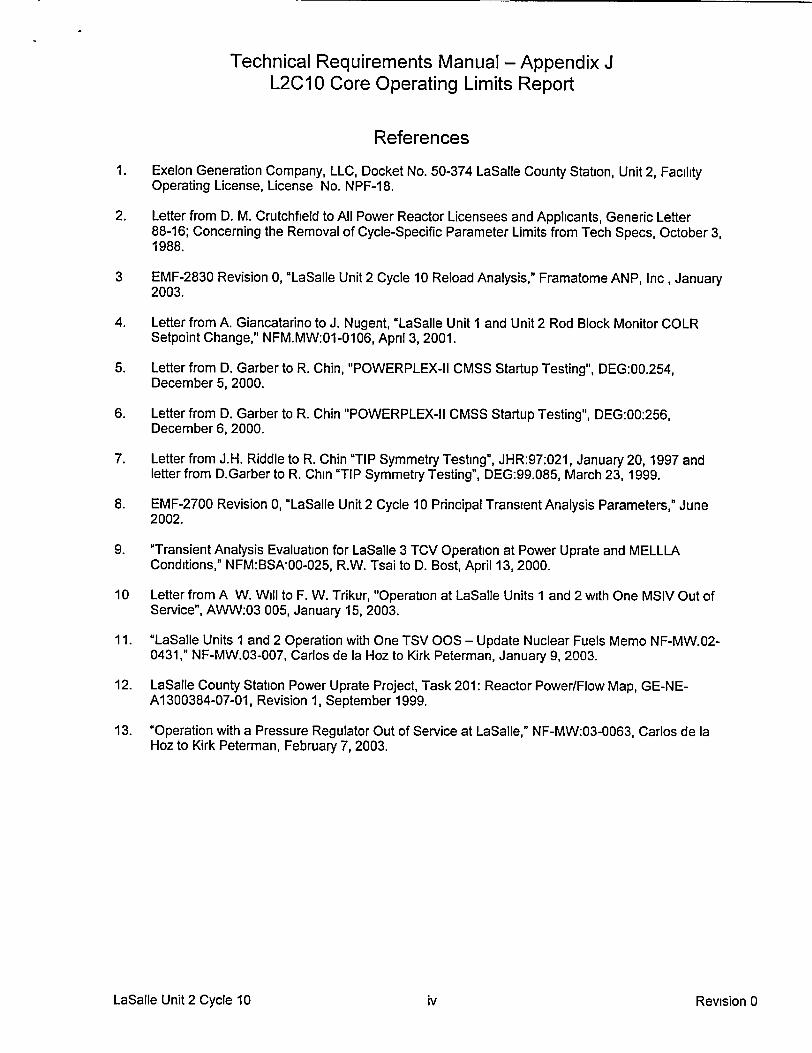
Table 2-4MCPRp for ATRIUM-9B Fuel
BOC - First Cycle-10 Sequence ExchangeTechnical Specification Scram Speeds (TSSS)
(Reference 3 Table 5 2)
EOOS CombinationCore Thermal Power (% of rated)
0 | 25 | 25(25.01) 60 80 | 80(80.01) | 100MCPRp
Base Case Operation 2 70 2 20 1 97 1 49
FHOOS Only 279 2 29 229 1 56
EOOS Case 1 2 79 2 29 2 29 1 58
EOOS Case 2 J 2.79 2 29 2 29
W | | |R M ! | 1 40
E N E ~i~iE R 1 41
| _ .lg~gllWS 1 41
Hufl 1 42_
1.76 1.58 1.50
Single Loop Operation (SLO) 2.71 2 21 1.98 1 50
SLO with FHOOS Only f 2.80 2 30 230 1 57
SLO with EOOS Case 1 2.80 2.30 2 30 1 59
SLO with EOOS Case 2 j 2.80 j 2.30 2 30
* Values are interpolated between relevant power levels.- For thermal limit monitoring at greater than 100% core thermal power, the 100% core thermal
power MCPRp should be applied.e Allowable EOOS conditions are listed in Section 6.
LaSalle Unit 2 Cycle 10 2-5 Revision 0

Technical Requirements Manual - Appendix JL2C10 Core Operating Limits Report
Table 2-5MCPRF limits for All Fuel
(Reference 3 Figure 5 1)
Flow (% of rated) MCPRF105 1.11100 1.1930 1.630 1.63
* Values are interpolated betweenrelevant flow values.
* Values are applicable to all OperatingDomains and EOOS conditions inSection 6.
* For thermal limit monitoring at greaterthan 105% rated core flow, utilize theMCPRF limit for 105% rated core flow.
LaSalle Unit 2 Cycle 10 2-6 Revision 0

Technical Requirements Manual - Appendix JL2C10 Core Operating Limits Report
3. Linear Heat Generation Rate (3.2.3)
3.1 Technical Specification Reference
Section 3.2.3.
3.2 Descrintion-
Limits provided in this section are only valid up to the first sequence exchange (deep-shallow swap) for the cycle, due to potential Control Blade History (CBH) impacts whichwere not performed as part of the original Cycle 10 licensing analyses A revision to thisdocument to account for any potential CBH impact will be issued at a future date, priorto the first sequence exchange for Cycle 10.
The LHGR Limit is the product of the LHGR Limit from Tables 3-1 or 3-2 and theminimum of either the power dependent LHGR Factor, LHGRFACp, or the flowdependent LHGR Factor, LHGRFACF. The applicable power dependent LHGR Factor(LHGRFACp) is determined from Table 3-3 or 3-4 for ATRIUM-1 0 fuel or Table 3-5 or3-6 for ATRIUM-9B fuel. The applicable flow dependent LHGR Factor (LHGRFACF) isdetermined from Table 3-7 for all fuel types.
Table 3-1Steady-State LHGR Limits for ATRIUM-10 Fuel
Al 0-4025B-1 5GV80-1 OOMAl 0-3982B-1 5GV80-1 OOM
A10-1 786B-OGV-1 00M(Bundle types 20, 21 and 22)
(Reference 3 Section 7.2 3)
Average Planar Exposure LHGR Limit(GWd/MT) (kW/ft)
0.0 13.415.0 13 455.0 9.164.0 7.3
LaSalle Unit 2 Cycle 10 3-1 Revision 0
Technical Requirements Manual - Appendix JL2C10 Core Operating Limits Report
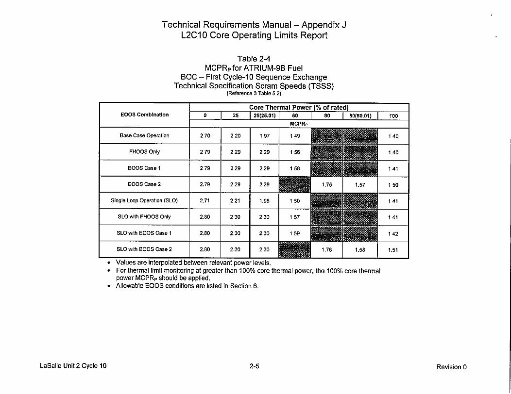
Table 3-2Steady-State LHGR Limits for ATRIUM-9B Fuel
A9-381 B-1 3GZ7-80MA9-384B-1 1 GZ6-80M
A9-391 B-14G8.0-1OOMA9-41 OB-1 9G8.0-1 OOMA9-383B-1 6G8.0-1 OOMA9-396B-1 2GZ-1 OOM
(Bundle types 14, 15, 16, 17, 18 and 19)(Reference 3 Section 7.2 3)
Average Planar Exposure LHGR Limit(GWd/MT) (kW/ft)
0.0 14.415.0 14.464.3 7.9
LaSalle Unit 2 Cycle 10 3-2 Revision 0

Technical Requirements Manual - Appendix JL2CIO Core Operating Limits Report
Table 3-3LHGRFACp for ATRIUM-10 Fuel
BOC - First Cycle-10 Sequence ExchangeNominal Scram Speeds (NSS)
(Reference 3 Table 5 1)
Core Thermal Power (% of rated)EOOS Combination 0 | 25 i 60 | 100
LHGRFACp multiplier
Base Case Operation 0 79 0 79 1.00 1.00
Single Loop Operation (SLO) 0 79 0 79 1.00 1 00
• Values are interpolated between relevant power levels.* For thermal limit monitoring at greater than 100% core thermal power, the
100% core thermal power LHGRFACp multiplier should be applied.* Allowable EOOS conditions are listed in Section 6.
LaSalle Unit 2 Cycle 10 3-3 Revision 0

Technical Requirements Manual - Appendix JL2C10 Core Operating Limits Report
Table 3-4LHGRFACpforATRIUM-10 Fuel
BOC - First Cycle-1 0 Sequence ExchangeTechnical Specification Scram Speeds (TSSS)
(Reference 3 Table 5 2)
Core Thermal Power (% of rated)EOOS Combination 0 1 25 1 60 | 80 80 (80.01) | 100
multiplier4-
Base Case Operation 0 78 0 78
FHOOS Only 0 65 0 65 0 95
EOOS Case 1 0 65 0 65 0.95
EOOS Case 2 0 65 0 65
Single Loop Operation (SLO) 0 78 0 78 1.00
SLO with FHOOS Only 0 65 0 65 0 95
1 00
1.00
1 00
0 95
1.00
1.00
1.00
0.95
SLO with EOOS Case 1 0 65 0.65
SLO with EOOS Case 2 0 65 [ 0.65
* Values are interpolated between relevant power levels.* For thermal limit monitoring at greater than 100% core thermal power, the 100% core thermal
power LHGRFACp multiplier should be applied.* Allowable EOOS conditions are listed in Section 6
LaSalle Unit 2 Cycle 10 3-4 Revision 0

Technical Requirements Manual - Appendix JL2C10 Core Operating Limits Report
Table 3-5LHGRFACp for ATRIUM-9B Fuel
BOC - First Cycle-10 Sequence ExchangeNominal Scram Speeds (NSS)
(Reference 3 Table 5 1)
Core Thermal Power (% of rated)
EOOS Combination 0 25 | 60 100
LHGRFACp multiplier
Base Case Operation 0 79 0 79 1 00 1.00
Single Loop Operation (SLO) 0.79 0 79 1 00 1 00
* Values are interpolated between relevant power levels.* For thermal limit monitoring at greater than 100% core thermal power,
the 100% core thermal power LHGRFACp multiplier should be applied.* Allowable EOOS conditions are listed in Section 6.
LaSalle Unit 2 Cycle 10 3-5 Revision 0

Technical Requirements Manual - Appendix JL2C10 Core Operating Limits Report
Table 3-6LHGRFACp for ATRIUM-9B Fuel
BOC - First Cycle-10 Sequence ExchangeTechnical Specification Scram Speeds (TSSS)
(Reference 3 Table 5 2)
EOOS CombinationCore Thermal Power (% of rated)
0 25 1 60 1 80 I 80 (80.01) F 100LHGRFACp multiplier
Base Case Operation 078 078 1 00
FHOOS Only 0 67 0 67 0 93
EOOS Case I 0 67 067 0.93
EOOS Case 2 | 0 67 | 0 67 0.79 1 0 86
1.00
1.00
1.00
0 90
1.00
1.00
1.00
0 90
Single Loop Operation (SLO) 0 78 078 1.00
SLO with FHOOS Only 067 0 67 | 0 93
SLO with EOOS Case 1 0 67 067 0 93
SLO with EOOS Case 2 | 0 67 | 0 67 079 1 086I
* Values are interpolated between relevant power levels.* For thermal limit monitoring at greater than 100% core thermal power, the
power LHGRFACp multiplier should be applieda Allowable EOOS conditions are listed in Section 6.
100% core thermal
LaSalle Unit 2 Cycle 10 3-6 Revision 0

Technical Requirements Manual - Appendix JL2C10 Core Operating Limits Report
Table 3-7LHGRFACF multipliers for All Fuel
(Reference 3 Figure 5 2)
Flow LHGRFACF(% of rated) Multiplier
105 1.0060 1.0030 0.850 0.85
* Values are interpolated between relevantflow values.
• For thermal limit monitoring above 105%rated core flow, utilize the 105% rated coreflow LHGRFACF multiplier.
* Values are applicable to all OperatingDomains and EOOS conditions in Section6.
LaSalle Unit 2 Cycle 10 3-7 Revision 0

Technical Requirements Manual - Appendix JL2C10 Core Operating Limits Report
4. Control Rod Withdrawal Block Instrumentation (3.3.2.1)
4.1 Technical Specification Reference
Table 3.3.2.1-1
4.2 Descrintion:
The Rod Block Monitor Upscale Instrumentation Setpoints are determined from therelationships shown below (Reference 4):
ROD BLOCK MONITOR ALLOWABLE VALUEUPSCALE TRIP FUNCTIO ALWBEVLU
Two Recirculation Loop 0.66 Wd + 54%Operation
Single Recirculation Loop 0.66 Wd + 48.7%Operation__ _ _ _ _ _ _ _ _ _
The setpoint may be lower/higher and will still comply with the Rod Withdrawal Error(RWE) Analysis because RWE is analyzed unblocked. The allowable value isclamped, with a maximum value not to exceed the allowable value for a recirculationloop flow (Wd) of 100%.
Wd - percent of recirculation loop flow required to produce a rated core flow of 108.5Mlb/hr.
LaSalle Unit 2 Cycle 10 4-1 Revision 0
Technical Requirements Manual - Appendix JL2C10 Core Operating Limits Report
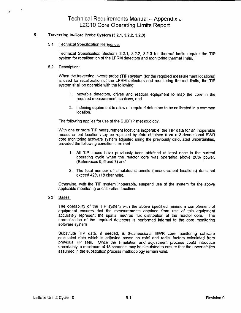
5. Traversing In-Core Probe System (3.2.1, 3.2.2, 3.2.3)
5 1 Technical Specification Reference:
Technical Specification Sections 3.2.1, 3.2.2, 3.2.3 for thermal limits require the TIPsystem for recalibration of the LPRM detectors and monitoring thermal limits.
5.2 Description:
When the traversing in-core probe (TIP) system (for the required measurement locations)is used for recalibration of the LPRM detectors and monitoring thermal limits, the TIPsystem shall be operable with the following-
1. movable detectors, drives and readout equipment to map the core in therequired measurement locations, and
2. indexing equipment to allow all required detectors to be calibrated in a commonlocation.
The following applies for use of the SUBTIP methodology.
With one or more TIP measurement locations inoperable, the TIP data for an inoperablemeasurement location may be replaced by data obtained from a 3-dimensional BWRcore monitoring software system adjusted using the previously calculated uncertainties,provided the following conditions are met.
1. All TIP traces have previously been obtained at least once in the currentoperating cycle when the reactor core was operating above 20% power,(References 5, 6 and 7) and
2. The total number of simulated channels (measurement locations) does notexceed 42% (18 channels).
Otherwise, with the TIP system inoperable, suspend use of the system for the aboveapplicable monitoring or calibration functions.
5 3 Bases:
The operability of the TIP system with the above specified minimum complement ofequipment ensures that the measurements obtained from use of this equipmentaccurately represent the spatial neutron flux distribution of the reactor core. Thenormalization of the required detectors is performed internal to the core monitoringsoftware system
Substitute TIP data, if needed, is 3-dimensional BWR core monitoring softwarecalculated data which is adjusted based on axial and radial factors calculated fromprevious TIP sets. Since the simulation and adjustment process could introduceuncertainty, a maximum of 18 channels may be simulated to ensure that the uncertaintiesassumed in the substitution process methodology remain valid.
LaSalle Unit 2 Cycle 10 5-1 Revision 0

Technical Requirements Manual - Appendix JL2C10 Core Operating Limits Report
6. Allowed Modes of Operation (B 3.2.2, B 3.2.3)
The Allowed Modes of Operation with combinations of Equipment Out-of-Service are as describedbelow:
--- OPERATING REGION- --
Equimen Outof ervie 3 POWERPLEXEquipment Out of Service ELLLA MELLLA ICF7 Coastdown3 Thermal LimitOptions1" 0' 1 Set Number 4'2
Base Case Operation - NSS Yes Yes Yes No 1
Single Loop Operation (SLO) - NSS Yes No" N/A No 2
Base Case Operation -TSSS Yes Yes Yes No 3
FHOOS5 Only - TSSS No8 No8 Yes No 4
EOOS Case I - TSSSFHOOS orTBVOOS9 Yes Yes Yes No 5
Except FHOOS8 Except FHOOS8
EOOS Case 2 - TSSSAny combination of TCV slow Yes Yes Yes No 6closure9 12, no RPT or FHOOS5 Except FHOOS8 Except FHOOS8
Single Loop Operation (SLO) - TSSS Yes No8 N/A No 7
SLO FHOOS5 Only - TSSS No8 No' N/A No 8
SLO with EOOS Case 1 - TSSSFHOOS5 or TBVOOS9 Yes No' N/A No 9
Except FHOOS8
SLO with EOOS Case 2 - TSSSAny combination of TCV slow Yes No" N/A No 10closure9,12, no RPT or FHOOS5 Except FHOOS 8
__
One TCV Stuck ClosedYes Yes Yes No See Note 9
One TSVOOS1 1
Yes Yes Yes No See Note 11
1 Each OOS Option may be combined with 1 SRVOOS, up to a 20 0F reduction in feedwatertemperature (without feedwater heaters considered OOS), up to 2 TIP machines OOS (or theequivalent number of TIP channels, i.e , 42% of the total number of channels) with 100% available atstartup, and/or up to 50% of the LPRMs OOS with an LPRM calibration frequency of 1250 EffectiveFull Power Hours (EFPH) (1000 EFPH +25%) (Reference 3 Tables 1.1 and 5.1 through 5.2)
2 In general, a more conservative thermal limit set that bounds the operating conditions can be used forthermal limit monitoring. However, using a more conservative thermal limit set will impose additionaloperating restrictions that are not required
3 Coastdown limits are not provided.
4 All EOOS scenarios and all limits provided are applicable from the beginning of the cycle (BOC) untilthe first Cycle-10 sequence exchange only. Applicable limits for operation beyond the first Cycle-10sequence exchange will be transmitted in a later revision to this document.
LaSalle Unit 2 Cycle 10 6-1 Revision 0

Technical Requirements Manual - Appendix JL2C10 Core Operating Limits Report
5 Feedwater heaters OOS (FHOOS) supports a reduction of up to 100OF in feedwater temperature.FHOOS may be an intentionally entered mode of operation or an actual OOS condition.
6The SLO boundary was not moved up with the incorporation of MELLLA. (MELLLA FCL is - 114.8%.)The power-flow boundary for SLO at power uprated conditions remains the ELLLA boundary for pre-uprate conditions (Reference 12). (ELLLA FCL is - 104.3%.)
7 ICF is analyzed up to 105% rated core flow.
8 If operating with FHOOS (alone or in combination with other EOOS), operation in the ELLLA orMELLLA region is supported by current transient analyses, but is administratively limited to less than100% flow control line due to stability concerns.
9 Operation prior to coastdown is only allowed when less than 10.5 million Ibm/hr steam flow and whenaverage position of 3 open TCVs is less than 50% open, with FCL <103%, and the MCFL setpoint >120%. TCV Stuck Closed may be in combination with any EOOS except TBVOOS, TCV SlowClosure, or TSVOOS. If in combination with other EOOS(s), thermal limits may require adjustment forthe other EOOS(s) as designated in Sections 1, 2, and 3 (Reference 9)
'° A single MSIV may be taken OOS (shut) under any and all OOS options as long as core thermalpower is maintained • 75% of 3489 MWt (Reference 10).
" A single TSV may be taken OOS (shut) and is bounded by operation with 1 TCV stuck closed.Therefore, operation with 1 TSVOOS is subject to the restrictions given for 1 TCV stuck closed inNote 9. The combination of 1 TSVOOS and 1 TCV stuck closed is not allowed. (Reference 11)
12 For temporary operation with a pressure regulator out of service (PROOS), the TCV slow closurelimits should be applied (Reference 13). The combination of PROOS and TCV slow closure is notallowed
LaSalle Unit 2 Cycle 10 6-2 Revision 0

Technical Requirements Manual - Appendix JL2C10 Core Operating Limits Report
7. Methodology (5.6.5)
The analytical methods used to determine the core operating limits shall be those previouslyreviewed and approved by the NRC, specifically those described in the following documents:
1. XN-NF-81-58 (P)(A), Revision 2 and Supplements I and 2, 'RODEX2 Fuel Rod Thermal-Mechanical Response Evaluation Model," March 1984.
2. Letter from Ashok C. Thadini (NRC) to R.A. Copeland (SPC), "Acceptance for Referencing ofULTRAFLOW'm Spacer on 9x9-IX/X BWR Fuel Design," July 28, 1993
3 ANF-524 (P)(A) Revision 2 and Supplements I and 2, "ANF Critical Power Methodology forBoiling Water Reactors," November 1990
4. XN-NF-80-19 (P)(A) Volume 1 Supplement 3, Supplement 3 Appendix F, and Supplement 4,'Advanced Nuclear Fuels Methodology for Boiling Water Reactors: Benchmark Results forCASMO-3G/MICROBURN-B Calculation Methodology," November 1990.
5 XN-NF-85-67 (P)(A) Revision 1, "Generic Mechanical Design for Exxon Nuclear Jet Pump BWRReload Fuel," September 1986.
6. ANF-913 (P)(A) Volume 1 Revision 1, and Volume 1 Supplements 2, 3, 4, "COTRANSA2. AComputer Program for Boiling Water Reactor Transient Analyses," August 1990.
7. XN-NF-84-105 (P)(A), Volume 1 and Volume 1 Supplements 1 and 2; Volume 1 Supplement 4,"XCOBRA-T: A Computer Code for BWR Transient Thermal-Hydraulic Core Analysis," February1987 and June 1988, respectively.
8 ANF-89-014 (P)(A) Revision 1 and Supplements 1 & 2, "Generic Mechanical Design forAdvanced Nuclear Fuels Corporation 9X9 - IX and 9x9 - 9X BWR Reload Fuel," October 1991.
9. EMF-2209 (P)(A), Revision 1, "SPCB Critical Power Correlation," July 2000.
10. ANF-89-98 (P)(A), Revision 1 and Revision 1 Supplement 1, "Generic Mechanical Design Criteriafor BWR Fuel Designs," May 1995.
11. ANF-91-048 (P)(A), "Advanced Nuclear Fuels Corporation Methodology for Boiling WaterReactors EXEM BWR ECCS Evaluation Model," January 1993.
12. Commonwealth Edison Company Topical Report NFSR-0091, "Benchmark ofCASMO/MICROBURN BWR Nuclear Design Methods," Revision 0 and Supplements onNeutronics Licensing Analysis (Supplement 1) and La Salle County Unit 2 benchmarking(Supplement 2), December 1991, March 1992, and May 1992, respectively.
13 EMF-85-74 (P)(A) Revision 0 and Supplement 1(P)(A) and Supplement 2(P)(A), "RODEX2A(BWR) Fuel Rod Thermal-Mechanical Evaluation Model," February 1998.
14. EMF-CC-074 (P) Volume 4 Revision 0, "BWR Stability Analysis: Assessment of STAIF with Inputfrom MICROBURN-B2, August 2000.
15. ANF-1125 (P)(A) and ANF-1125(P)(A) Supplements 1 and 2, "ANFB Critical Power Correlation,"Advanced Nuclear Fuels Corporation, April 1990.
16 ANF-1125 (P)(A) Supplement 1 Appendix E, "ANFB Critical Power Correlation Determination ofATRIUMT™-9B Additive Constant Uncertainties," September 1998.
LaSalle Unit 2 Cycle 10 7-1 Revision 0
Technical Requirements Manual - Appendix JL2C10 Core Operating Limits Report
17. Commonwealth Edison Topical Report NFSR-0085 Revision 0, "Benchmark of BWR NuclearDesign Methods," November 1990
18 Commonwealth Edison Topical Report NFSR-0085 Supplement 1 Revision 0, 'Benchmark ofBWR Nuclear Design Methods - Quad Cities Gamma Scan Comparisons," April 1991.
19. Commonwealth Edison Topical Report NFSR-0085 Supplement 2 Revision 0, "Benchmark ofBWR Nuclear Design Methods - Neutronic Licensing Analyses," April 1991.
20 ANF-CC-33 (P)(A) Supplement 1 Revision 1 and Supplement 2, "HUXY: A Generalized MultirodHeatup Code with 10CFR50, Appendix K Heatup Option," August 1986 and January 1991,respectively.
21. XN-NF-80-19 (P)(A) Volume 4 Revision 1, "Exxon Nuclear Methodology for Boiling WaterReactors: Application of the ENC Methodology to BWR Reloads," June 1986.
22. XN-NF-80-19 (P)(A) Volume 3 Revision 2, "Exxon Nuclear Methodology for Boiling WaterReactors, THERMEX: Thermal Limits Methodology Summary Description," January 1987.
23. ANF-91-048 (P)(A) Supplement 1 and Supplement 2, "BWR Jet Pump Model Revision forRELAX," October 1997.
24. XN-NF-80-19 (P)(A) Volumes 2, 2A, 2B, and 2C, "Exxon Nuclear Methodology for Boiling WaterReactors: EXEM BWR ECCS Evaluation Model," September 1982.
25. XN-NF-80-19 (P)(A) Volume I and Supplements 1 and 2, "Exxon Nuclear Methodology for BoilingWater Reactors - Neutronic Methods for Design and Analysis," March 1983.
26. EMF-2158(P)(A) Revision 0, "Siemens Power Corporation Methodology for Boiling WaterReactors- Evaluation and Validation of CASMO-4/MICROBURN-B2," Siemens PowerCorporation, October 1999.
LaSalle Unit 2 Cycle 10 7-2 Revision 0