Large Underground Radioactive Waste Storage Tanks .../67531/metadc711301/m2/1/high... · Large...
11
Large Underground Radioactive Waste Storage Tanks SuccHsfully Cleaned at Oak Ridge National Laboratory Karen Billingsley Solutions to Environmental Problems, Inc. Oak Ridge, TN 37830 Marshall Johnson Lockheed Martin Energy Systems Oak Ridge, TN 37831 Jane Powell U.S. Department of Energy Oak Ridge, TN 37830 Barry L. Burks The Providence Group Knoxville, TN 37931 Cavanaugh Mims U.S. Department of Energy Oak Ridge, TN 37830 Dirk Van Hoesen Lockheed Martin Energy Research Oak Ridge, TN 37831 This work was authored by a contractor of the U.S. Government under contract No. DE-AC05-980R22700. Accordingly, the U.S. Government retains a nonexclusive, royalty-free license to publish the published form of this contribution, or allow others to do so for U.S. Government purposes.
Transcript of Large Underground Radioactive Waste Storage Tanks .../67531/metadc711301/m2/1/high... · Large...

Large Underground Radioactive Waste Storage Tanks SuccHsfully Cleaned at Oak Ridge National Laboratory
Karen Billingsley Solutions to Environmental Problems, Inc.
Oak Ridge, TN 37830
Marshall Johnson Lockheed Martin Energy Systems
Oak Ridge, TN 37831
Jane Powell U.S. Department of Energy Oak Ridge, TN 37830
Barry L. Burks The Providence Group Knoxville, TN 37931
Cavanaugh Mims U.S. Department of Energy
Oak Ridge, TN 37830
Dirk Van Hoesen Lockheed Martin Energy Research
Oak Ridge, TN 37831
This work was authored by a contractor of the U.S. Government under contract No. DE-AC05-980R22700. Accordingly, the U.S. Government retains a nonexclusive, royalty-free license to publish the published form of this contribution, or allow others to do so for U.S. Government purposes.

DISCLAIMER
This report was prepared as an account of work sponsored by an agency of the United States Government Neither the United States Government nor any agency thereof. nor any of their employm, makes any warranty, express or implied, or assumes any legal liability or responsibility for the accuracy. completeness, or use- fulness of any information, apparatus, product, or process disclosed, or represents that its use would not infringe privately owned rights. Reference herein to any spe- cific commercial product, process, or service by trade name, trademark, manufac- turer, or otherwise does not necessarily constitute or imply its endorsement, recom- mendation, or favoring by the United States Government or any agency thereof. The views and opinions of authors expressed herein do not necessarily state or reflect those of the United States Government or any agency thereof.

LARGE UNDERGROUND RADIOACTNE WASTE STORAGE TANKS SUCCESSFULLY CLEANED AT OAK RIDGE NATIONAL LABORATORY
Karen Billingsley STEP, Inc.
1006 Floyd Culler Court Oak Ridge, Tennessee 37830
(423) 481-7837
Cavanaugh Minx U.S. Department of Energy Oak Ridge Operations Office
P.O. Box 2001 Oak Ridge, TN 37830
(423) 576-948 1
ABSTRACT
Bany L. Burks The Providence Group
11020 Solway School Road Suite 107
Knoxville, TN 37931 (423) 927-5519
Jane Powell U. S. Department of Energy Oak Ridge Operations Office
P.O. Box 2001 Oak Ridge, TN 37830
(423) 576-7807
Waste retrieval operations were successfully completed in two large underground radioactive waste storage tanks in 1997. The U. S. Department of Energy (DOE) and the Gunite Tanks Team worked cooperatively during two 10-week waste removal campaigns and removed approximately 58,300 gallons of waste from the tanks. About 100 gallons of a sludge and liquid heel remain in each of the 42,500 gallon tanks. These tanks are 25 ft. in diameter and 11 f€. deep, and are located in the North Tank Farm in the center of Oak Ridge National Laboratory. Less than 2% of the radioactive contaminants remain in the tanks, proving the effectiveness of the Radioactive Tank Cleaning System, and accomplishing the first field-scale cleaning of contaminated underground storage tanks with a robotic system in the DOE complex.
I. INTRODUCTION
Oak Ridge National Laboratory is located about 25 miles from Knoxville in eastern Tennessee. The Gunite and Associated Tanks - Operable Unit (GAAT-OU) consists of 16 underground radioactive waste storage tanks that are located in the center of ORNL, near the cafeteria, in the Bethel Valley watershed. The gunite process was used to construct 12 of the tanks in 1943-44. Workers sprayed a cement and sand mixture over a wire mesh and reinforcing rod frames. A bituminous material applied between the interior layers of the tanks provided additional leak protection. The tanks stored radioactive
,
Marshall Johnson Lockheed Martin Energy Systems
P.O. Box 2008 MS 6342 Oak Ridge, TN 3783 1
(423) 576-9450
Dirk Van Hoesen Lockheed Martin Energy Research
P.O. Box 2008 MS 6338 OakRidge, TN 37831
(423) 574-7264
and hazardous liquid and sludge wastes produced during the 40-year operating life of the tanks. Waste generation began during the Manhattan Project pilot-scale plutonium production operations, and continued through a variety of research and development activities at O N . The tanks were removed from service in the early 1970s, well beyond the original design life of the tanks. A waste removal campaign during the early 1980's removed some waste from 6 tanks, located in the South Tank Farm (STF), but left sludge heels and other debris. In-leakage from groundwater and rain has contributed to the volume of waste remaining in the tanks.
The remotely operated Radioactive Tank Cleaning System and the innovative approach developed and implemented for the Gunite Tanks Remediation Project has led to projected schedule acceleration of 9 years and a $120 million reduction in the overall project cost. Lessons learned during the successful clean up of the two lower risk tanks lead to improvements to both the RTCS and the integrated approach. and will be applied to the remediation of the remaining higher risk gunite tanks. The approach "piloted" through the Gunite Tanks Remediation Project could lead to greater cast and schedule improvements at other sites with similar tanks, such as Hanford, Idaho and Savannah River.
11. REGULATORY APPROACH
The Federal Facility Agreement (FFA) among DOE, the Environmental Protection Agency (EPA), and the
Powell 1

Tennessee Department of Environment and Conservation (TDEC) integrates all regulatory requirements applied to the clean up efforts conducted on the Oak Ridge Reservation. The Gunite Tanks Remediation Project complies with the FFA. Characterization activities and studies on potential remediation approaches were performed from the late 1980s through early 1994. The results were compiled in a combined Remedial InvestigatiodFeasibiIity Study (RVFS) . The RVFS identified si@cant uncertainties in the risks presented by the gunite tanks. To resolve the uncertainties, DOE, EPA, and TDEC agreed to perform a Treatability Study ( T S ) under the provisions of the Comprehensive Environmental Response, Compensation, and Liability Act (CERCLA). The degree to which the tanks could be cleaned, and the cost and schedule for the potential clean-up options were evaluated during supplemental tank characterization, tank risk assessments, and remediation technology investigations that were undertaken in tandem during the TS.
HI. WASTE CHARACTERIZATION
Samples from several locations in each tank were analyzed to develop information to resolve criticality, risk. and other uncertainties. Sampling activities indicated that approximately 82,000 gallons of sludge with a total activity of about 62,000 Ci were contained in the gunite tanks. Analyses focused on determining the radioactive and hazardous constituents present in the samples. Selected samples were subjected to leach tests to develop information on the rate and amount of contaminants that might be released from the waste. Contaminant concentrations varied signrficantly from tank to tank, with cesium-137 and strontium-90 representing the bulk of the radioactivity in the tank wastes. Several long half-life isotopes are present at concentrations above 100 nCi/gm, thus the wastes are classified as "transuranic" according to DOE criteria. The wastes also contain elevated levels of metals such as chromium, lead, and mercury, so the waste is considered "hazardous" according to EPA criteria. Sigrufxcant contamination was also found on the tank walls.
A pathway model was developed using detailed, realistic information including site-specific groundwater models and actual waste leach data. Modeling efforts were directed at evaluating the current and future risk presented by the tanks and how much risk reduction could be achieved by removing waste h m the tanks, or incorporating the waste in a grout form within the tanks. White Oak Creek (WOC), located approximately 1000 ft. from the STF was utilized as the reference point of exposure since it receives drainage from the gunite tanks
area. Assessments based on the pathway model estimated that at least 90% of the waste should be removed from the gunite tanks. This action reduces the risk levels at WOC to below the CERCLA threshold risk target probability of developing cancer M n g a lifetime to lo4, or one out of a thousand individuals. Strontium- 90 was determined to be the primary contributor to risk due to its high concentration and mobility in the environment. The risk varied greatly from tank to tank and is dependent on the contaminant levels and waste volumes.
IV. TECHNOLOGY TESTS
A series of remediation technology tests and demonstrations were identified to provide data on waste removal performance, cost, and schedule. These included "cold" tests at a mock-up facility, and "hot" tests in the NTF in tanks W-3 and W-4, the two smallest and least contaminated of the gunite tanks. The benefits of this approach included:
lower safety and programmatic risks (equipment problems were worked out and workers were trained in low-risk situations); and TS information was developed in actual field conditions during waste retrieval and tank characterization operations.
The tested technologies were robust and flexible. Selection criteria included the ability to effectively remove a wide variety of wastes ranging from soft to hard sludge, wall scale, and other debris expected to be encountered during the tank remediation. DOE, TDEC, and EPA decided on a two-phase remediation approach for the gunite tanks after reviewing the TS results (through the completion of tank W-3 waste removal), and with public input.
Phase I is an interim action to remove waste from eight tanks (W-3 through W-10) that essentially contain all the contaminants in the GAAT-OU. The amount of waste removed during the retrieval operations of the interim action will be determined based on the final results of the TS, and on the conditions experienced in each tank. Removed waste will be temporarily stored in one or more of the large gunite tanks in the STF until its scheduled transfer (under the ORNL Integrated Tank Waste Management Plan) to the existing permitted Melton Valley Storage Tanks (MVST). A private contractor, selected through a separate ongoing DOE action, undertaken as part of the ORNL Site Treatment Plan, will perform waste treatment before final disposal
Powell 2

at the Waste Isolation Pilot Plant (WIPP), or the Nevada Test Site (NTS)
Phase I1 of the Gunite tanks remediation will be a final action conducted as part of the closure process for the Bethel Valley Watershed that will include the GAAT- OU and inactive or surpIus facilities at ORNL.
V. THE RADIOACTIVE TANK CLEANING SYSTEM W C S )
The RTCS consists of several subsystems including:
0
0
the waste dislodging and conveyance subsystem ( W a c ) , the Modified Light Duty Utility Arm (MLDUA), a large robotic manipulator arm; the Houdini remotely operated vehicle; the Balance of Plant (BOP) and instrumentation and control systems associated with each major subsystem; auxiliary systems for containment and decontamination of the subsystems; and remote lighting, and video observation to assist with waste removal operations.
0
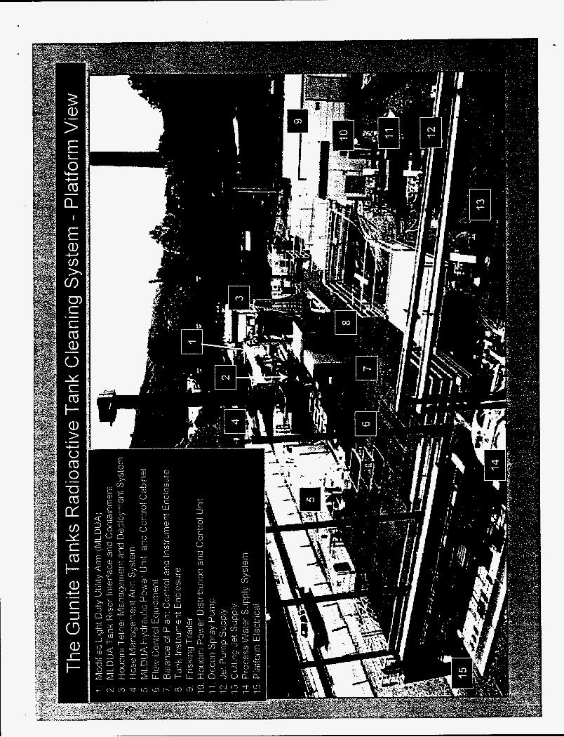
Special tools that are deployed by the MLDUA, or Houdini were designed for waste characterization and wall scarifying. The major pieces of equipment are positioned on a platform over the tank before the start of waste removal operations.
A Waste Dislodging and Conveyance System (WD&C)
The WD&C subsystem includes the confined sluicing endeffector (CSEE) tool, a hose management arm (HMA), a containment structure, and flow control equipment box (FCEB). Operation of the CSEE is analogous to a high-performance carpet cleaner that employs rotating water jets to mobilize dirt, while a vacuum removes the dirty water. As the CSEE cutting jets rotate, soft and hard waste material is broken up and dislodged by about 10 gpm of water at 7,000 psi. An inlet located in the center of the cutting jets connects to a transfer hose and conveyance line located in the HMA. The CSEE is equipped with handles that are grasped by the MLDUA and Houdini for positioning within the tank.
The HMA minimizes loads on the MLDUA and Houdini by providing a positioning system for the transfer hose, as well as a pipeline for conveyance of the waste up and out of the tank The HMA consists of two
horizontal pipes connected to a vertical positioning mast. All of the HMA joints are connected with a swivel and motorized so the transfer hose attached to the CSEE can be positioned in the vicinity of the area of the tank to be cleaned. The joints are backdriveable so@e MLDUA and Houdini can easily move the CSEE and HMA during waste removal operations. The HMA mast contains a jet pump powered by 7,000 psi water at 10 gpm to generate a suction at the CSEE inlet and provide the motive force to move the waste up the conveyance line to the WD&C outlet. The conveyance line exits the WD&C containment and mates to the FCEB (Figure 1 - # 6), equipped with a coriollis flow meter, an automated sampling device, a flush system for back washing the conveyance line, and a rupture disc to prevent over pressurization of the conveyance line.
The HMA can be retracted through a decontamination spray ring into a box and tube containment structure (Figure 1 - # 4) located on the platform above the tank. The containment structure is fitted with eight glove ports for access to power, control, and hose connections, and for maintenance operations. A spray wand is also provided for additional decontamination. The box-and-tube serve as the containment structure during transport of the HMA between tanks.
B. Modified Light Duty Arm (MLDUA)
The MLDUA is an eightdegree-of-fieedom manipulator that can deploy a 200-lb payload through risers as small as 12 inches in diameter. The MLDUA is equipped with a gripper end-effector allowing it to grasp other tools such as the CSEE. It has a vertical reach of 50-ft and an effective horizontal reach of 17.5-ft (including gripper and CSEE). The MLDUA is equipped with two cameras located at the mast and arm junction and an additional camera in the gripper. The system is designed for radioactive and high pH environments and includes a purge system to help prevent airborne and liquid contamination from leaking into the arm. The skid mounted MLDUA (Figure 1 - # 1) is positioned by a crane onto the tank platform where it rests on adjustable outriggers. A second skid contains the hydraulic power unit. oil reservoir, pumps. oil chiller. and controls cabinets (Figure 1 - # 5).
The tank riser interface and containment box (TRIC) provides a containment area where endeffectors are attached to the MLDUA (Figure 1 - # 2). The phone- booth-sized TRIC has glove and pass through ports on the three Lexan panel sides and a door and pass-through port on the fourth side, The TRIC is attached at the top
Powell 3

to the vertical mast housing via an expandable bellows and to a decontamination spray ring at the bottom. A spray wand is also provided inside the TRIC for additional decontamination capability
C. The Houdini Remotely Operated Vehicle
The Houdini vehicle has four major components. The heart of the system is a tethered, hydraulically powered track driven vehicle. Its 44” x 48” chassis can fold to fit through the 24-in. gunite tank risers. The
‘
vehicle is equipped with a squeegee-tipped plow blade and a tidegree-of-freedom Schilling Titan 111 manipulator arm. The manipulator has a 240-lb payload capacity and is used to deploy the end-effectors as well as to retrieve debris from the tank. The vehicle is equip@ with two color video cameras and lights. Power and control signals are provided to the vehicle through a drum-mounted tether located in the upper portion of the containment structure. The vehicle is stored in the lower part of the containment structure that is equipped with Lexan panels and glove ports for maintenance (Figure 1 - #3). A containment bezel provides additional glove and pass-through ports and mates to a decontamination spray ring.
D. Balance of Plant (BOP)
The BOP includes several auxiliary systems that provide support to the waste removal equipment. The low pressure water pump skid provides an interface with the plant process water system and supplies water to the decontamination spray ring, jet pump, and cutting jet pump skids (Figure 1 - # 7, # 11, # 12, and #13). An air compressor provides purge air for the MLDUA and air for water system control valves. A skid mounted High Efficiency Particulate Air (HEPA) system with a continuous sampler provides negative pressure to the tanks to control airborne contamination. Electric power is supplied for 120; 240; and 480-volt uses. Two continuous air monitors check for airborne contamination at the site perimeter. A continuous monitor checks dose rate levels at the FCEB during transfer operations. A half-body monitor is used to check for personnel contamination.
A graphical user interface links the low-level control systems of the CSEE, HMA, FCEB, and the associated valves, air compressors, water supplies, and high pressure pumps for the BOP. From this user interface at the control console, one operator can remotely control all three systems. Equipment operators use several remote controlled video cameras to monitor waste removal activities, operations in the containment structures, and
conditions in the receiving tank. VI. FACILITY MODIFICATIONS
Facility modifications to support the waste removal TS in tanks W-3 and W-4 in the North T F Farm 0 began in October 1996. Modifications included the addition of seven 24411 tank access ports. or risers; the erection of a 40x70-ft steel platform to support the waste removal equipment; and the installation of electrical and water services, a portable HEPA ventilation system, and tank level monitors. Two trailers were installed for the operations control center and health and safety support, and small modular buildings were installed for a frisk station, half-body monitor, and equipment storage. Facility modifications were complete in April 1997.
VII. TANK INSPECTIONS AND CHECKOUT OPERATIONS
A preliminary tank inspection and characterization were conducted in tanks W-3 and W-4 in early May 1997, just before the waste removal equipment was transported to the platform. The visible portions of the wall were inspected with the video camera to check for damaged areas, and to identfi visual markers for equipment operator orientation. The walls were covered with up to %in. thick scale, but found to be in good condition.
Cold tests of the RTCS were completed in early May 1997. The system was shut down for relocation to the NTF on May 13, 1997. Relocation and installation of the RTCS required about six weeks. A phased readiness assessment (begun during cold testing) was completed DOE gave approval to begin limited checkout operations on June 24, 1997.
The supernate level was pumped down to 2-ft above the sludge layer to retain shielding for initial wall contamination surveys. The MLDUA was used to deploy the characterization end-effector (CEE) to obtain baseline radiation readings on the wall surfaces above the supernate. Wall scrapings were obtained for analysis. From July 1-7 the MLDUA deployed the CSEE to perform wall-cleaning tests in several small areas of the tank at pressures varying from 1500 to 6000 psi. The MLDUA was deployed with a ruler and measured the sludge depth at 24- in. for an estimated sludge volume of 5500-gal. The Houdini was deployed with hydraulic shears to remove a bundle of cable, conduit, and pipe obstructing its landing area.
During the checkout operations several equipment failures occurred that required a cumulative down time of
Powell 5

about three weeks for the MLDUA, Houdini and WD&C systems. The MLDUA failed components included two hydraulic leaks caused by faulty O-ring seals, an oil temperature sensor, and an encoder cable that jumped its guide. These were all straightfomard repairs. A rupture disc that prevents over pressurization of the waste conveyance line failed twice during supernate pumping. The failures were attributed to effects other than over pressurization. The rupture disc location was not conducive to easy replacement so the system was modified to relocate it to a more accessible location in the FCEB. A new rupture disc with a slightly higher burst rating was installed and no further failures have been experienced. The Houdini vehicle is subjected to rough treatment as it operates in the sludge waste on the tank floor. As a result a number of hydraulic fittings have leaked or broken, and occasionally cables were damaged. A second vehicle has been designed to protect or
eliminate the vulnerable components. None of the equipment failures involved extensive down time of expensive part replacement.
VIII. WASTE REMOVAL OERATIONS
Waste removal operations were conducted in tank W-3 from July through September 1997. The RTCS equipment was moved to tank W-4 and operations restarted in November 1997 and were completed in FebruaIy 1998. The MLDUA and Houdini vehicle were both used to deploy the CSEE to remove the sludge waste. The MLDUA worked best for removing thicker piles of sludge, while the Houdini was better at cleaning the floor surface. The MLDUA and Houdini worked well together, as the plow on Houdini pushed sludge toward the MLDUA and accumulated piles of sludge to be sluiced. The majority of sludge was removed from tank W-3 over a two-week period in mid August. Core samples were obtained from the tank walls using a coring tool deployed by the Houdini vehicle. Analyses showed that more than 90% of the wall contamination is found within 1/8 inch of the surface rather than migrating deep into the gunite walls. The walls were cleaned with the h4LDUA and CSEE at 7000 psi. This scarifying action removed loose contamination and much of the scale on the walls. During the wall cleaning a dense fog developed in the tank limiting visibility. The ability to preprogram robotic trajectories for the MLDUA enabled wall cleaning without fear of collisions with the tank walls or floor. A survey with the CEE after wall cleaning showed that radioactivity in the walls was reduced by about 20%. A small amount of grit remained on the tank floor when the water from the wall cleaning had been pumped away. An attempt was made to plow this material into a pile, but there was too little material
left to form a pile. A new endeffector was designed to provide a small intake orifice at the tank floor. This was coupled to a pneumatic vacuum system to perform final tank floor cleaning. This tool worked well until a hose failed. \.:
It was determined that the tank was sufficiently clean and that further operations were not justified. The residual sludge and liquid left in the tank was estimated at 100 gallons. Visual inspections of tank W-3’s interior and review of the preliminary tank shell core results showed that most of the waste had been removed from the tank. In early October DOE, EPA, and TDEC agreed that the goals of the TS and ROD had been achieved for tank W-3. The RTCS was prepared for relocation to tank W-4 where waste removal activities were completed in January 1998.
E. WASTE REMOVAL OPERATIONS PERFORMANCE EVALUATION
An evaluation of the RTCS performance of waste removal operations in tank W-3 was prepared and used to obtain EPA and TDEC agreements. DOE requested that EPA and TDEC agree that the goals of the interim Record of Decision had been met for tank W-3 and that equipment relocation to tank W-4 could be initiated. Current evaluations based on characterization data developed in the RVFS addendum, information collected in the Shift Supervisor log during operations, and results from analysis of the core samples and wall scrapings show that waste removal operations were successfid in tanks W-3 and W-4. The RTCS removed an estimated 328 Ci of the original 340 Ci present in tank W-3, or more than 96 % contaminant removal efficiency. The 100-gallon liquidkludge heel remaining in the tank represents less than 0.24 % of the 42,500 gallon capacity. In tank W-4, 1241 Ci of the original 1252 Ci were removed. for a contaminant removal efficiency of 99%.
The estimated radionuclide inventory remaining is 12 Ci in tank W-3 and 11 Ci in tank W-4. Video inspections show that the majority of waste was removed from the tanks. A liquidsludge heel of 1 inch covers an area of the floor about 20 feet in diameter. Conservatively assuming that all the 100 gallons of this heel is sludge, the estimated remaining heel inventory is approximately 13 Ci in both tanks. An estimated 90% of the wall scale was removed during the cleaning operation leaving a residual tank shell inventory of about 10 Ci in tanks W-3 and W-4. Wall cores were taken to verify RTCS cleaning capabilities. Over 90% of the reSidual contamination is located in the first 1/8 inch ofthe wall and may be removable with a higher pressure scarifying
Powell 6
. operation.
waste removal operations was determined by reviewing the shift logs and estimating the duration of the equipment operations. The contamination removed during each of the operations was plotted against the operating time to produce a cleaning efficiency summary. This information highlights two major conclusions regarding the performance of the RTCS.
First, it is very clear that efficiency (measured by Ci/hr removed) is highest when RTCS operations are '
focused on bulk sludge removal. This situation becomes important when operating costs, schedule constraints, and particularly the potential for damagdfailure of expensive and hard-to-replace RTCS equipment is considered In concert with the overall goal to remove as much of the Gunite tank contaminan t inventory as possible, it should be noted that less-thancomplete waste removal might be warranted in certain situations. In particular, the low removal rates associated with the wall cleaning operation coupled with the high potential for equipment damage presented by the limited visibility suggest that this operation may not be warranted in all cases, particularly if any wall degradation is encountered during the cleaning operation.
The effectiveness of the RTCS performing major
The second major observation is associated with the overall operational efficiency of the RTCS. The duration of just over 80 hours of actual waste removal operations occurred during a period from July 7 to September 18. This same period included 530 possible working hours (assuming five 10-hour days per week). This calculates to an overall RTCS productivity factor of 15%. It should be noted that during this period major equipment failure and subsequent maintenance required 270 hours, while coring, sampfing, and CEE measurements required 50 hours. If these activities are removed from the available working time, the revised productivity factor is 38%. This is a more realistic estimate of the RTCS productivity and is consi&red a reasonable factor recognizing the complexity of the RTCS system and the timeconsuming health and safety requirements for exposure and radiation control associated with the radioactive operating environment.
X. CONCLUSION AND FUTURE PLANS
DOE and the Gunite Tanks Team achieved the major goals of the interim ROD by successfully removing most of the waste from tanks W-3 and W-4. Several other major programmatic successes were also achieved. This success validated the "learn as you progress" approach adopted from the inception of the Gunite Tanks Remediation Project. The cornerstone of this approach is
the evolution in operations from low risk to higher risk activities. The first step inthis process involved testing major pieces of equipment at the vendor site to demonstrate basic operability. The next step was the full- scale cold test where system integration ptoblems were worked out, modifications to improve operability were made, operating procedures were developed and tested, and operators were trained. The hot test operations in two less contaminated tanks demonstrate that the RTCS and the project team can successllly operate in actual radioactive conditions. This provides a high degree of confidence that the same operations can be performed safely and effectively in the larger, highercontaminant- level tanks W-5 through W-10.
Generally, the RTCS performed well, and the benefit of its robust and flexible capabilities was clearly demonstrated The RTCS handled the unexpected challenges associated with encountering more than 2 f& of sludge waste as opposed to the expected 8 inches. The redundant capabdities of the MLDUA and the Houdini allowed operations to continue even when one of the systems was down for repair. The value of the approach of integrated waste removal equipment deployment pursued by DOE Oak Ridge Operations (DOE-ORO) was also demonstrated. DOE-ORO chose to maximize the integration of the gunite remediation tanks activities with ongoing efforts in the DOE Office of Science and Technology (OST) Tanks Focus Area and Robotics programs. This effective "leveraging" resulted in major cost and schedule savings to the DOE-ORO remediation program and benefited OST by accelerating the field deployment of waste removal equipment, which will provide experience and information useful to other DOE sites.
Several possible improvements in the performance of the RTCS wen? identified during the W-3 operations. The WD&C system worked well with minimal equipment problems. Deployment and retraction of the HMA required up to four hours each day, so efforts will be directed at developing methods that will allow the HMA to be left in the tank for extended periods. It was determined that the CSEE cutting jet pressures were not high enough to remove the 1/8 inch of gunite that contains the majority of residual contamination from the tank wall. A CSEE system capable of 35,000-p~i operation is currently being developed. The MLDUA performed well once the initial hydraulic and control cable failures were repaired. The programmed operating capability of the MLDUA was critical for successllly cleaning the tank walls. This operation could not have been performed with direct visual operation due to the fog produced by the cleaning operation. The Houdini
Powell 7
was very effective removing debris and its maneuverability proved critical in performing several operations such as floor cleaning and deployment of the coring tool. The Houdini experienced frequent hydraulic system problems during the W-3 operations limiting its availability. Modifications to the hydraulic system are planned on a second version of the Houdini scheduled for delivery in late FY 98.
No significant health and safety problems were encountered, and contamination and personnel exposure controls worked effectively. This was due in large part to the experience gained and the improvements made during the cold tests. The decontamination spray ring system and the hand held spray wands located in the containment structures effectively cleaned the in-tank equipment and prevented sludge buildup. The negative pressure HEPA filtered ventilation system, in concert with the containment enclosures were successful in controlling contamination in the platform areas around the equipment. The half-body monitor proved to be much more efficient and sensitive for personnel fkisking than hand held equipment.
Modifications were performed in the STF on tanks W-5 through W-10 to remove unneeded equipment, add new access ports and platforms, and install utilities. The RTCS equipment was set up on the plagorm over tank W-6, where waste removal activities are currently being performed. Waste wil l be removed from the remaining tanks through the end of FT 2000. Beginning in early FY 1999, waste transfers from the temporary storage tanks (W-8 and W-9) to the MVST are planned as part of O m ’ s Integrated Tank Waste Management Plan. Waste transfers will continue in parallel with the waste removal operations until all of the tanks are clean.
ACKNOWLEDGMENTS
The success of the Gunite Tanks Remediation Project described in this article is a result of the commitment and hard work of all the following team members: P. Abkon, A Beal, J. Blank, L. Curtis, H. Davis, K. Deroos, J. Emison, D. Falter, C. Fitzgerald, B. Frederick, R. Glassell, W. Glover, 0. Hale, R Hobson, L. Holder, M. Johnson, S. Killough, D. Kington, P. Lloyd, L. Love, M. Mayes, H. Mccusker, J. Miller, R Morgan, J. Morse, E. Mwphree, G. Palowsky, J. Platfoot, J. Powell, J. Randolph, D. Reynolds, K. Rice, R Riner, R Russell, V. Rule, J. Rutenber, H. Toy, C. Wiles, B. Womble, H. Wright, C. Wyser, and many other Oak Ridge National Laboratory craft and professional personnel.
Powell 8
M98005748 I lllllllllll111111111111111 llllllllll lllll111ll11111111
Report Number (14) (36l\l L / @ p --9%30 9 co/vFC 9%0?05---
Publ. Date (1 1)
Sponsor Code (18) vo e UC Category (1 9)
179 < 0 5
19980702 065
DOE