Large scale production of carbon nanotube arrays … scale production...Liquefied petroleum gas...
7
Chinese Science Bulletin © 2007 SCIENCE IN CHINA PRESS Springer www.scichina.com www.springerlink.com Chinese Science Bulletin | November 2007 | vol. 52 | no. 21 | 2896-2902 Large scale production of carbon nanotube arrays on the sphere surface from liquefied petroleum gas at low cost ZHANG Qiang, HUANG JiaQi, WEI Fei † , XU GuangHui, WANG Yao, QIAN WeiZhong & WANG DeZheng Beijing Key Laboratory of Green Chemical Reaction Engineering and Technology, Department of Chemical Engineering, Tsinghua University, Beijing 100084, China Liquefied petroleum gas (LPG), a cheap industrial material, is used as carbon source to produce carbon nanotube (CNT) arrays on ceramic spherical surface on a large scale in the floating catalyst process. The ceramic spheres provide huge surface area and good mobility, leading to the mass production of CNT arrays continuously. The arrays obtained from the surface are of good alignment, and the purity is as high as 97.5%. With the decrease of the growth temperature, CNTs in the array form with small-diameter of about 13 nm can be obtained. Therefore, with the industrial fuel as carbon source and the ceramic sphere as substrate, CNT arrays can easily be produced on large scale at low cost. carbon nanotube arrays, liquefied petroleum gas, large scale, production Carbon nanotube (CNT) arrays have become the focus of nanoscience and nanotechnology since they were first synthesized in 1996 [1] . The CNTs in the array form are of almost the same aspect ratio, good orientation and high purity, showing excellent properties. Therefore, the original CNT arrays can be used directly as field emis- sion devices, anisotropic conductive materials, mem- brane filtration materials, super springs, filaments, super strong fibers, nanobrushes, sensors and many other functional materials. Even if we destroy the orientation of CNT array, CNTs are still found to have better per- formance than the agglomerated single-walled carbon nanotubes (SWCNTs) and multi-walled carbon nano- tubes (MWCNTs) in improving the electronic, mechanic and thermal properties of the polymer [2] . The key of re- alizing these promising applications and achieving its industrialization is the mass production of CNT arrays at low cost. Various synthesis methods have been devel- oped, including porosity assisted chemical vapor deposi- tion (CVD) [1,3] , plasma enhanced CVD [4] , thermal CVD [5―7] , and floating catalyst CVD [8―14] . For CNT ar- rays growth, a pure carbon source and a plane substrate are often needed. And batch operations are taken in the above CVD process [3―14] . But for the practical use of a material, a continuous production on large scale with low cost is commonly required. A generic substrate and cheap carbon source should be developed for the large scale fabrication of CNT arrays. Generally, high-purity carbon sources such as CO and hydrocarbon including methane, ethylene, acetylene, cyclohexane, benzene, toluene, xylene are widely used to synthesize CNTs [3―17] . But these pure carbon sources are very expensive (with a price always higher than 1200 $/ton in China) and are limited in quantity as compared with cheaper fuels such as liquefied petroleum gas (LPG, about 400 $/ton in China), coal, and natural gas. However, these cheap fuels often contain some sul- fur which will severely poison the catalyst. There were Received June 19, 2007; accepted September 7, 2007 doi: 10.1007/s11434-007-0458-8 † Corresponding author (email: [email protected]) Supported by the Foundation for the Authors of National Excellent Doctoral Disser- tations of China (Grant No. 200548), the National Natural Science Foundation of China (Grant No. 20606020), the National Basic Research Program of China (Grant No. 2006CB0N0702), and the Key Project of the Ministry of Education of China (Grant No. 106011)
Transcript of Large scale production of carbon nanotube arrays … scale production...Liquefied petroleum gas...
Chinese Science Bulletin
© 2007 SCIENCE IN CHINA PRESS
Springer
www.scichina.com www.springerlink.com Chinese Science Bulletin | November 2007 | vol. 52 | no. 21 | 2896-2902
Large scale production of carbon nanotube arrays on the sphere surface from liquefied petroleum gas at low cost
ZHANG Qiang, HUANG JiaQi, WEI Fei†, XU GuangHui, WANG Yao, QIAN WeiZhong & WANG DeZheng Beijing Key Laboratory of Green Chemical Reaction Engineering and Technology, Department of Chemical Engineering, Tsinghua University, Beijing 100084, China
Liquefied petroleum gas (LPG), a cheap industrial material, is used as carbon source to produce carbon nanotube (CNT) arrays on ceramic spherical surface on a large scale in the floating catalyst process. The ceramic spheres provide huge surface area and good mobility, leading to the mass production of CNT arrays continuously. The arrays obtained from the surface are of good alignment, and the purity is as high as 97.5%. With the decrease of the growth temperature, CNTs in the array form with small-diameter of about 13 nm can be obtained. Therefore, with the industrial fuel as carbon source and the ceramic sphere as substrate, CNT arrays can easily be produced on large scale at low cost.
carbon nanotube arrays, liquefied petroleum gas, large scale, production
Carbon nanotube (CNT) arrays have become the focus of nanoscience and nanotechnology since they were first synthesized in 1996[1]. The CNTs in the array form are of almost the same aspect ratio, good orientation and high purity, showing excellent properties. Therefore, the original CNT arrays can be used directly as field emis- sion devices, anisotropic conductive materials, mem- brane filtration materials, super springs, filaments, super strong fibers, nanobrushes, sensors and many other functional materials. Even if we destroy the orientation of CNT array, CNTs are still found to have better per- formance than the agglomerated single-walled carbon nanotubes (SWCNTs) and multi-walled carbon nano- tubes (MWCNTs) in improving the electronic, mechanic and thermal properties of the polymer[2]. The key of re- alizing these promising applications and achieving its industrialization is the mass production of CNT arrays at low cost. Various synthesis methods have been devel- oped, including porosity assisted chemical vapor deposi- tion (CVD)[1,3], plasma enhanced CVD[4], thermal CVD[5―7], and floating catalyst CVD[8―14]. For CNT ar- rays growth, a pure carbon source and a plane substrate
are often needed. And batch operations are taken in the above CVD process[3―14]. But for the practical use of a material, a continuous production on large scale with low cost is commonly required. A generic substrate and cheap carbon source should be developed for the large scale fabrication of CNT arrays.
Generally, high-purity carbon sources such as CO and hydrocarbon including methane, ethylene, acetylene, cyclohexane, benzene, toluene, xylene are widely used to synthesize CNTs[3―17]. But these pure carbon sources are very expensive (with a price always higher than 1200 $/ton in China) and are limited in quantity as compared with cheaper fuels such as liquefied petroleum gas (LPG, about 400 $/ton in China), coal, and natural gas. However, these cheap fuels often contain some sul-fur which will severely poison the catalyst. There were
Received June 19, 2007; accepted September 7, 2007 doi: 10.1007/s11434-007-0458-8 †Corresponding author (email: [email protected]) Supported by the Foundation for the Authors of National Excellent Doctoral Disser-tations of China (Grant No. 200548), the National Natural Science Foundation of China (Grant No. 20606020), the National Basic Research Program of China (Grant No. 2006CB0N0702), and the Key Project of the Ministry of Education of China (Grant No. 106011)

ZHANG Qiang et al. Chinese Science Bulletin | November 2007 | vol. 52 | no. 21 | 2896-2902 2897
AR
TIC
LES
C
HE
MIC
AL
EN
GIN
EE
RIN
G
few reports on the direct use of LPG, natural gas or coal to synthesize CNTs as carbon precursor[18―22]. Prokudina et al.[18] successfully synthesized agglomerate MWCNTs with LPG, but no information of sulfur was given in the report. Our group had reported the direct synthesis of agglomerated MWCNTs from the decomposition of the LPG containing 13 ppm sulfur with Fe/Mo/Al2O3 cata-lyst and the MWCNT products were similar to that ob-tained from pure carbon source such as propylene[19]. Recently, CNT arrays were synthesized from LPG on plate substrate. However, surface area of the plate sub-strate is often limited and its mobility is poor, leading to short pass in the reactor. Only 1 g/h CNT array were obtained with plate substrate[11]. Here, it is noted that the quantity of CNT array is proportional to the growth area. If the growth substrate with larger surface area is used, more CNT arrays can be obtained[23,24]. Spherical parti-cles have the largest surface area. Specifically, when cheap inorganic oxide spheres with diameters around 1 mm and total volume of 1 dm3 are introduced as the growth substrates in the floating catalyst process, the surface for the CNT growth is as large as 5 m2 (equals to that of 10000 pieces of one-inch wafer). Using spheres as growth substrates and cyclohexane as carbon source in a conventional and laboratory scale floating catalyst reactor, we can produce 200 g aligned multi-walled CNT arrays per hour[24]. If using the cheap fuel such as LPG as carbon source to produce CNT ar-rays on sphere substrate, CNT arrays can be obtained at low cost.
In this article, ceramic balls were used as the CNT array growth substrate and LPG as carbon source with-out purification to controllably produce CNT arrays in the floating catalyst process at low cost. This provides a new methodology to reduce the cost of CNT array pro-duction, leading to the potential application of CNT ar-rays in future.
1 Experimental
Typical experiments were performed on a two-stage furnace with a length of 350 and 650 mm, respectively. Ferrocene was used as the catalyst precursor and LPG was used as the carbon source. The substrates, large amounts of spheres, were commercially available ball- milling ceramic media. The spheres, sometimes along with a quartz substrate as reference, were first put in the part of the tube of the second furnace with a temperature
of about 800℃. The LPG was then let into the reactor in the atmosphere of 90.9% Ar and 9.1% H2. The feed rate of LPG and flow rate of the carrier gas were 50 sccm and 440 sccm respectively. After a certain period of growth time, the LPG was stopped and cooled to room temperature. Then the ceramic spheres with CNT array were collected for further characterization.
All the products are characterized by the scanning electronic microscopy (JSM 7401F, excited at 3 kV), the transmission electron microscopy (JEM 2010, excited at 200 kV), the Raman Spectroscopy (RM 2000, Renishaw, excited at 514.5 nm) and thermal gravimetric analysis (TGA, TA2050, heated at 20℃/min).
2 Results and discussion
The morphologies of ceramic spheres before and after the reaction are shown in Figure 1(a) and (b). As shown in Figure 1(a), the surfaces of the spheres are relatively clean. They are round in shape and of 700―800 μm in diameter. After the deposition of CNT arrays, the prod-ucts turn into the black color macroscopically with rough outer surface (Figure 1(b)). The uniform black color of the products indicates that the spheres are uni-formly coated by carbon. Notably, the diameter of sphere after CNT growth was about 1100―1200 μm, significantly larger than that of the host sphere. From the SEM image in Figure 1(c), a layer of vertical aligned CNT array with a height of 200 μm is found on the sur-face of the ceramic sphere. From the high magnification images of CNT array in Figure 1(d), we can see that the CNTs show good alignment, and some are straight while others are curve. The tortuous factor of the curve CNTs was approximately 1.22±0.05[25]. Due to the interactions between the above two kinds of CNTs, the arrays grow on the bottoms of the sphere surfaces synchronously with internal stress[26,27]. Compared with the plate sub-strates, the ceramic balls have larger surface areas and the CNT array cover almost all the surface of the ball. Therefore, CNT arrays can be mass produced using LPG as carbon source and ceramic ball as substrate.
The growth of CNT array from LPG is complex in the floating catalyst process. The structure of CNT array such as the CNT diameter and length can be modulated by changing the growth temperature and growth time, etc. Also the carbon conversion is discussed to illustrate the controllable CNT array synthesis.

2898 ZHANG Qiang et al. Chinese Science Bulletin | November 2007 | vol. 52 | no. 21 | 2896-2902
Figure 1 (a) The ceramic sphere morphology before CNT array growth; (b) the morphology of CNT array growth on the sphere when LPG used as car-bon source; (c) SEM images of CNT array growth on the sphere; (d) HRSEM images of good alignment CNT array.
2.1 The CNT diameter modulated by growth tem-perature
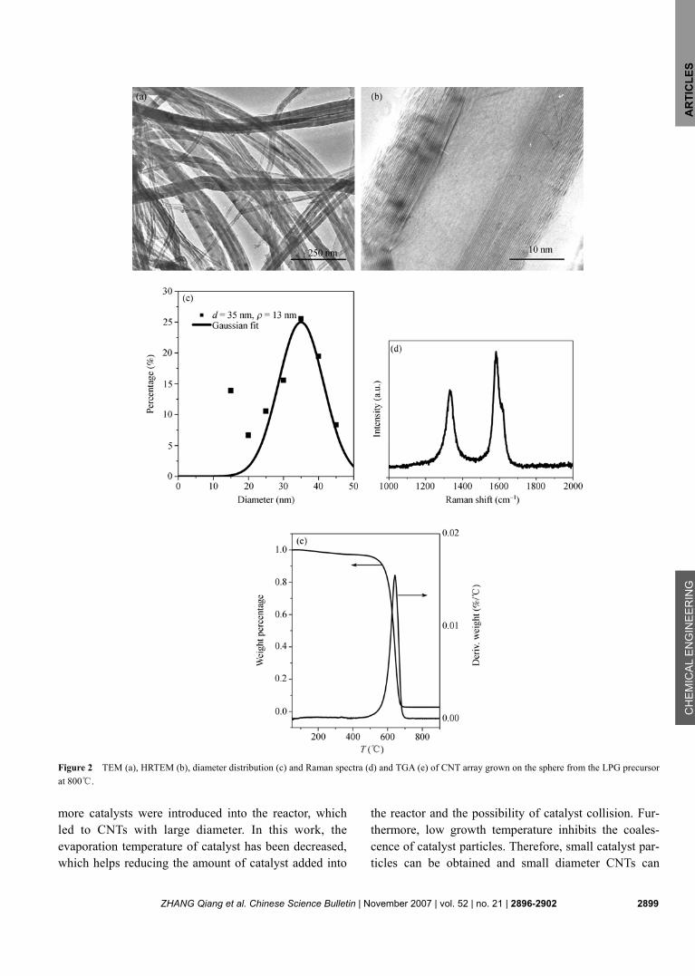
High growth temperature was always used for CNT ar-ray synthesis in floating catalyst process. The TEM and HRTEM images of CNT obtained at 800℃ are shown in Figure 2(a) and (b). They are of high purity and no other carbon impurity such as carbon spheres, carbon fi-bers, or amorphous carbon is found in the TEM images. The out-diameter of CNT is from 10 to 50 nm, while the number of the graphite layers is about 10 to 70. Figure 2(b) shows good graphitization of the CNT in the array. Catalyst particles are found at the end, or in the middle of a single CNT, coated by graphite layers. This indi-cates that the CNT obtained by this method is not hollow entirely. The Raman spectrum of the CNT grown on the ceramic sphere is shown in Figure 2(d). The two main peaks in 1580 cm−1 (G peak) and 1350 cm−1 (D peak) in the Raman spectra of the MWCNT are the resonance peak of graphite and the scattering peak of disordered component, respectively. Therefore, the intensity ratio (ID/IG) is commonly used to characterize the degree of
crystalline perfection of the samples. The value of ID/IG of CNTs synthesized on the surface is 0.72, which shows crystalline perfection and confirms well with the HRTEM images. From the TGA results of CNT array in Figure 2(e), it can be seen that purity of the CNT array is as high as 97.5%.
When the growth temperature is reduced to 700℃, CNT arrays can also be synthesized on the ceramic spheres. The TEM and HRTEM images of the CNTs in the array are shown in Figure 3(a) and (b). It can also be found that the CNTs are of high purity. The CNTs show small outer diameter of 4―15 nm and inner diameter of 2―10 nm, respectively. This indicates that the CNTs have high hollow inner ratio. Meanwhile, the number of walls is about 6―15, much less than that of CNTs grown at 800℃. The CNTs look clean and with no other amor-phous carbon coated as shown in Figure 3(b). However, the number of defects increases and CNTs curve greatly with a high tortuous factor of 1.41±0.08. In most reports concerning the floating catalyst process, the growth temperature was usually above 800℃[8―14,23,24,26,27], and
ZHANG Qiang et al. Chinese Science Bulletin | November 2007 | vol. 52 | no. 21 | 2896-2902 2899
AR
TIC
LES
C
HE
MIC
AL
EN
GIN
EE
RIN
G
Figure 2 TEM (a), HRTEM (b), diameter distribution (c) and Raman spectra (d) and TGA (e) of CNT array grown on the sphere from the LPG precursor at 800℃.
more catalysts were introduced into the reactor, which led to CNTs with large diameter. In this work, the evaporation temperature of catalyst has been decreased, which helps reducing the amount of catalyst added into
the reactor and the possibility of catalyst collision. Fur-thermore, low growth temperature inhibits the coales-cence of catalyst particles. Therefore, small catalyst par-ticles can be obtained and small diameter CNTs can
2900 ZHANG Qiang et al. Chinese Science Bulletin | November 2007 | vol. 52 | no. 21 | 2896-2902
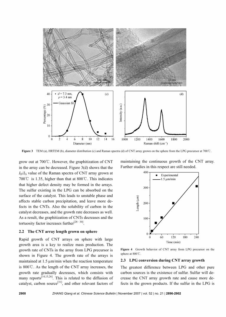
Figure 3 TEM (a), HRTEM (b), diameter distribution (c) and Raman spectra (d) of CNT array grown on the sphere from the LPG precursor at 700℃.
grow out at 700℃. However, the graphitization of CNT in the array can be decreased. Figure 3(d) shows that the ID/IG value of the Raman spectra of CNT array grown at 700℃ is 1.35, higher than that at 800℃. This indicates that higher defect density may be formed in the arrays. The sulfur existing in the LPG can be absorbed on the surface of the catalyst. This leads to unstable phase and affects stable carbon precipitation, and leave more de-fects in the CNTs. Also the solubility of carbon in the catalyst decreases, and the growth rate decreases as well. As a result, the graphitization of CNTs decreases and the tortuosity factor increases further[28―30].
2.2 The CNT array length grown on sphere
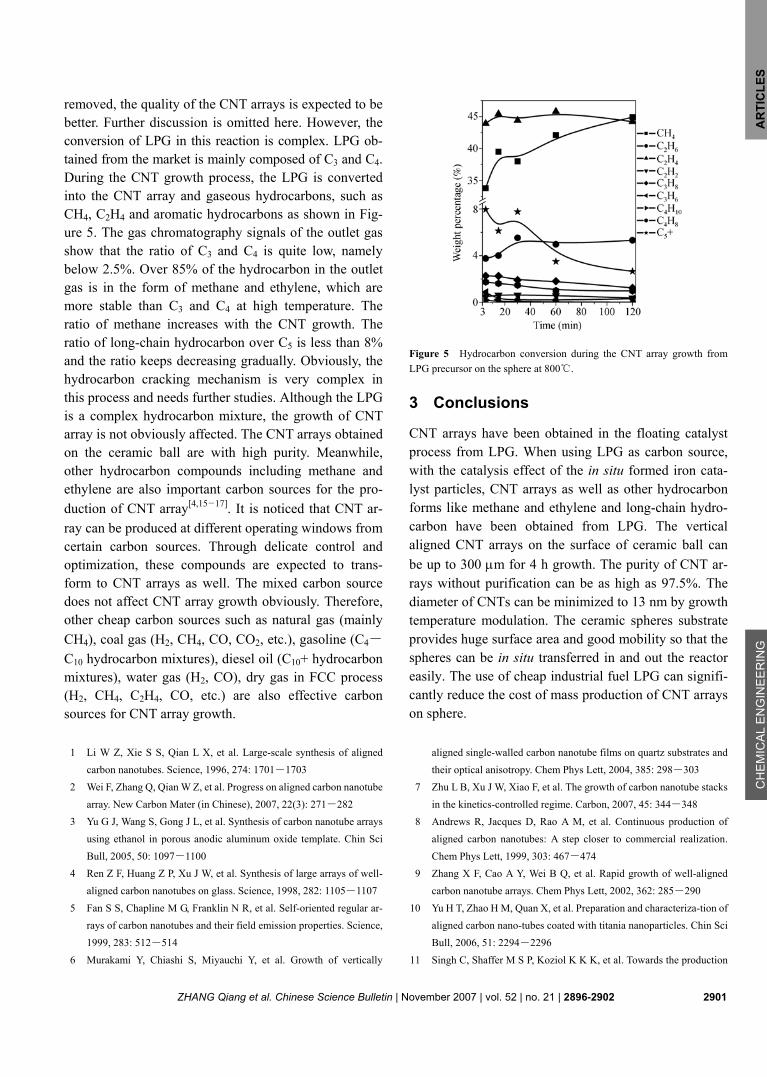
Rapid growth of CNT arrays on sphere with large growth area is a key to realize mass production. The growth rate of CNTs in the array from LPG precursor is shown in Figure 4. The growth rate of the arrays is maintained at 1.5 μm/min when the reaction temperature is 800℃. As the length of the CNT array increases, the growth rate gradually decreases, which consists with many reports[14,15,26]. This is related to the diffusion of catalyst, carbon source[31], and other relevant factors of
maintaining the continuous growth of the CNT array. Further studies in this respect are still needed.
Figure 4 Growth behavior of CNT array from LPG precursor on the sphere at 800℃.
2.3 LPG conversion during CNT array growth
The greatest difference between LPG and other pure carbon sources is the existence of sulfur. Sulfur will de-crease the CNT array growth rate and cause more de-fects in the grown products. If the sulfur in the LPG is
ZHANG Qiang et al. Chinese Science Bulletin | November 2007 | vol. 52 | no. 21 | 2896-2902 2901
AR
TIC
LES
C
HE
MIC
AL
EN
GIN
EE
RIN
G
removed, the quality of the CNT arrays is expected to be better. Further discussion is omitted here. However, the conversion of LPG in this reaction is complex. LPG ob-tained from the market is mainly composed of C3 and C4. During the CNT growth process, the LPG is converted into the CNT array and gaseous hydrocarbons, such as CH4, C2H4 and aromatic hydrocarbons as shown in Fig-ure 5. The gas chromatography signals of the outlet gas show that the ratio of C3 and C4 is quite low, namely below 2.5%. Over 85% of the hydrocarbon in the outlet gas is in the form of methane and ethylene, which are more stable than C3 and C4 at high temperature. The ratio of methane increases with the CNT growth. The ratio of long-chain hydrocarbon over C5 is less than 8% and the ratio keeps decreasing gradually. Obviously, the hydrocarbon cracking mechanism is very complex in this process and needs further studies. Although the LPG is a complex hydrocarbon mixture, the growth of CNT array is not obviously affected. The CNT arrays obtained on the ceramic ball are with high purity. Meanwhile, other hydrocarbon compounds including methane and ethylene are also important carbon sources for the pro-duction of CNT array[4,15―17]. It is noticed that CNT ar-ray can be produced at different operating windows from certain carbon sources. Through delicate control and optimization, these compounds are expected to trans-form to CNT arrays as well. The mixed carbon source does not affect CNT array growth obviously. Therefore, other cheap carbon sources such as natural gas (mainly CH4), coal gas (H2, CH4, CO, CO2, etc.), gasoline (C4―
C10 hydrocarbon mixtures), diesel oil (C10+ hydrocarbon mixtures), water gas (H2, CO), dry gas in FCC process (H2, CH4, C2H4, CO, etc.) are also effective carbon sources for CNT array growth.
Figure 5 Hydrocarbon conversion during the CNT array growth from LPG precursor on the sphere at 800℃.
3 Conclusions
CNT arrays have been obtained in the floating catalyst process from LPG. When using LPG as carbon source, with the catalysis effect of the in situ formed iron cata-lyst particles, CNT arrays as well as other hydrocarbon forms like methane and ethylene and long-chain hydro-carbon have been obtained from LPG. The vertical aligned CNT arrays on the surface of ceramic ball can be up to 300 μm for 4 h growth. The purity of CNT ar-rays without purification can be as high as 97.5%. The diameter of CNTs can be minimized to 13 nm by growth temperature modulation. The ceramic spheres substrate provides huge surface area and good mobility so that the spheres can be in situ transferred in and out the reactor easily. The use of cheap industrial fuel LPG can signifi-cantly reduce the cost of mass production of CNT arrays on sphere.
1 Li W Z, Xie S S, Qian L X, et al. Large-scale synthesis of aligned
carbon nanotubes. Science, 1996, 274: 1701―1703 2 Wei F, Zhang Q, Qian W Z, et al. Progress on aligned carbon nanotube
array. New Carbon Mater (in Chinese), 2007, 22(3): 271―282 3 Yu G J, Wang S, Gong J L, et al. Synthesis of carbon nanotube arrays
using ethanol in porous anodic aluminum oxide template. Chin Sci Bull, 2005, 50: 1097―1100
4 Ren Z F, Huang Z P, Xu J W, et al. Synthesis of large arrays of well- aligned carbon nanotubes on glass. Science, 1998, 282: 1105―1107
5 Fan S S, Chapline M G, Franklin N R, et al. Self-oriented regular ar-rays of carbon nanotubes and their field emission properties. Science, 1999, 283: 512―514
6 Murakami Y, Chiashi S, Miyauchi Y, et al. Growth of vertically
aligned single-walled carbon nanotube films on quartz substrates and their optical anisotropy. Chem Phys Lett, 2004, 385: 298―303
7 Zhu L B, Xu J W, Xiao F, et al. The growth of carbon nanotube stacks in the kinetics-controlled regime. Carbon, 2007, 45: 344―348
8 Andrews R, Jacques D, Rao A M, et al. Continuous production of aligned carbon nanotubes: A step closer to commercial realization. Chem Phys Lett, 1999, 303: 467―474
9 Zhang X F, Cao A Y, Wei B Q, et al. Rapid growth of well-aligned carbon nanotube arrays. Chem Phys Lett, 2002, 362: 285―290
10 Yu H T, Zhao H M, Quan X, et al. Preparation and characteriza-tion of aligned carbon nano-tubes coated with titania nanoparticles. Chin Sci Bull, 2006, 51: 2294―2296
11 Singh C, Shaffer M S P, Koziol K K K, et al. Towards the production

2902 ZHANG Qiang et al. Chinese Science Bulletin | November 2007 | vol. 52 | no. 21 | 2896-2902
of large-scale aligned carbon nanotubes. Chem Phys Lett, 2003, 372(5-6): 860―865
12 Zhao Z B, Qu J Y, Qiu J S, et al. Water-assisted fabrication of aligned microsized carbon tubes made of self-assembled multi-wall carbon nanotubes. Chem Comm, 2006, 14: 594―596
13 Puretzky A A, Geohegan D B, Jesse S, et al. In situ measurements and modeling of carbon nanotube array growth kinetics during chemical vapor deposition. Appl Phys A, 2005, 81: 223―240
14 Singh C, Shaffer M S, Windle A H. Production of controlled archi-tectures of aligned carbon nanotubes by an injection chemical vapour deposition method. Carbon, 2003, 41: 359―368
15 Wang Y, Wei F, Luo G H, et al. The large-scale production of carbon nanotubes in a nano-agglomerate fluidized-bed reactor. Chem Phys Lett, 2002, 364: 568―572
16 Wang M Z, Li F, Yang Q H, et al. Advances in synthesizing and pre-paring carbon nanotubes from different carbon sources. New Carbon Mater, 2003, 18: 250―264
17 Zhang Q, Qian W Z, Wen Q, et al. The effect of phase separation in Fe/Mg/Al/O catalysts on the synthesis of DWCNTs from methane. Carbon, 2007, 44: 1645―1650
18 Prokudina N A, Shishchenko E R, Joo O S, et al. Carbon nanotube RLC circuits. Adv Mater, 2000, 12: 1444―1447
19 Qian W Z, Yu H, Wei F, et al. Synthesis of carbon nanotubes from liq-uefied petroleum gas containing sulfur. Carbon, 2002, 40: 2968―2970
20 Wang Z Y, Zhao Z B, Qiu J S. In situ synthesis of super-long Cu nanowires inside carbon nanotubes with coal as carbon source. Car-bon, 2006, 44: 1845―1847
21 Wang Z Y, Zhao Z B, Qiu J S. Synthesis of branched carbon nanotubes from coal. Carbon, 2006, 44: 1321―1324
22 Qiu J S, Li Q X, Wang Z Y, et al. CVD synthesis of coal-gas-derived
carbon nanotubes and nanocapsules containing magnetic iron carbide and oxide. Carbon, 2006, 44: 2565―2568
23 Zhang Q, Qian W Z, Xiang R, et al. In situ growth of carbon nano-tubes on inorganic fibers with different surface properties. Mater Chem Phys, 2007, doi: 10.1016/j.matchemphys.2007.07.020
24 Xiang R, Luo G H, Qian W Z, et al. Large area growth of aligned CNT arrays on spheres: Towards the mass and continuous production. Chem Vapor Depos, 2007, doi:10.1002/cvde.200704249
25 Zhou W P, Wu Y L, Wei F, et al. Elastic deformation of multiwalled carbon nanotubes in electrospun MWCNTs-PEO and MWCNTs-PVA nanofibers. Polymer, 2005, 46: 12689―12695
26 Xiang R, Luo G H, Qian W Z, et al. Encapsulation, compensation, and substitution of catalyst particles during continuous growth of carbon nanotubes. Adv Mater, 2007, 19: 2360—2363
27 Zhang Q, Zhou W P, Qian W Z, et al. Synchronous growth of verti-cally aligned carbon nanotubes with pristine stress in the heteroge-neous catalysis process. J Phys Chem C, 2007, 111: 14638—14643
28 Ren W C, Li F, Cheng H M. Evidence for, and an understanding of, the initial nucleation of carbon nanotubes produced by a floating catalyst method. J Phys Chem B, 2006, 110: 16941―16946
29 Luo T, Chen L Y, Bao K Y, et al. Solvothermal preparation of amor-phous carbon nanotubes and Fe/C coaxial nanocables from sulfur, ferrocene, and benzene. Carbon, 2006, 44: 2844―2848
30 Barreiro A, Kramberger C, Rummeli M H, et al. Control of the single-wall carbon nanotube mean diameter in sulphur promoted aerosol-assisted chemical vapour deposition. Carbon, 2007, 45: 55―61
31 Zhong G F, Iwasaki T, Robertson J, et al. Growth kinetics of 0.5 cm vertically aligned single-walled carbon nanotubes. J Phys Chem B, 2007, 111: 1907―1910