Large Machine Installation and Maintenance - … Manuals/Large Machine...Large Machine Installation...
26
Important Notice: In order to remain in compliance with UL and ETL standards, this manual must be kept on file. Printed 2011 Large Machine Installation and Maintenance
-
Upload
hoangkhanh -
Category
Documents
-
view
222 -
download
3
Transcript of Large Machine Installation and Maintenance - … Manuals/Large Machine...Large Machine Installation...
Important Notice: In order to remain in compliance with UL and ETL standards, this manual must be kept on file.
Printed 2011
Large Machine Installation and Maintenance

Automatic Devices Company Page -2 2121 South 12th Street Allentown, PA 18103 800 360-2321
Table of Contents
Section Description Page
1A Warranty 3 1B Loss or damage 4 1C General description 5 1D Receiving, handling and storage 7 2A Mounting 7 2B Wiring 8 2C Start‐Up 9 3A Cable attachment (grooved
drums) 11
3B Sprocket drive machines 12 4A Initial testing 13 4B Limit switch adjustments 13 5 Maintenance 15 6 Troubleshooting and repair 17 DC machine operating
instructions 26
Models equipped with “TV”
frequency drive option 29
Wiring Diagrams 33

Automatic Devices Company Page -50 2121 South 12th Street Allentown, PA 18103 800 360-2321
Standard Limit Switch Assembly
Deceleration Limits TV Machines (longer
dwell) [Black]
Overtravel (TV Machines) or Stop
(DC Machines) Limit Switches
[White]
Deceleration Limit Switch Assembly
Field connection Terminal strip
Ground
Standard MCSA Control Box
Limit cam (compression fit)
Limit switch
Direction relative to control pushbuttons
TV Frequency Drive Control Box
Frequency Drive Module
Field connection Terminal strip
Automatic Devices Company Page -3 2121 South 12th Street Allentown, PA 18103 800 360-2321
Curtain Machine Instruction Manual ADC Curtain Machines 1/4 Horsepower or Larger
1. INTRODUCTION
1A. WARRANTY: (a) Our equipment is guaranteed against defective material and workmanship for a period of one year from date of shipment, provided however that any claim for defective material or workmanship must be made in writing received by us within the appropriate warranty period, and the material or equipment claimed to be defective returned to us whose liability under this guarantee shall be restricted to the replacement or repair of defective materials and workmanship. In no event will we honor any claim for special or consequential damages, nor will we accept back-charges for work performed on our equipment. (b) If any modifications or alterations are made to our equipment without our prior approval in writing, our warranty is automatically voided. (c) Our guarantee against defective material and workmanship applies only to the normal and conventional use and application of our equipment, as operated or capable of operation on our plant testing facilities. The guarantee does not apply to unusual, unique, untested or unconventional uses and applications. (d) Commodities not manufactured by us are warranted and guaranteed only to the extent and in the manner warranted and guaranteed to us by the manufacturer, and then only to the extent we are able to enforce such warranty or guarantee.
General Information

Automatic Devices Company Page -4 2121 South 12th Street Allentown, PA 18103 800 360-2321
(e) We will not guarantee the satisfactory operation of our curtain machinery when used with curtain track not of our manufacture. (f) We will not be held responsible for the failure of our equipment to operate properly at the point of installation unless all information, instructions and drawings requisite to the installation of our equipment and to existing job site conditions are furnished to us in writing prior to our formally acknowledging the order. The above warranty provisions will not apply if it is concluded by us that our equipment was not properly installed and that without our prior approval alterations and/or modifications were made to approved shop drawings supplied by us and/or to the jobsite, subsequent to the submissions of the aforementioned information, instructions and drawings. (g) The giving of or failure to give any advice or recommendations by us shall not constitute any warranty by or impose any liability upon us. (h) No liability whatsoever shall attach to us until said products have been paid for. (i) In the interest of improving the operation, appearance and production of our equipment, we reserve the right to make design changes at any time without giving prior notice to the trade.
1B. LOSS OR DAMAGE: Even though most shipments are delivered in perfect condition, there is always the possibility of loss or damage. In order to eliminate the possibility of inconvenience and possible additional expense, we urge that you carefully follow these suggestions: When a shipment is delivered to the carrier their agent receipts for it in good condition. It is securely packed; otherwise, they would not accept it and according to the terms on the Bill of Lading, a legally binding contract, the carrier agrees to deliver it to you in the same perfect condition. If these goods are damaged, they should not be accepted until the carrier's agent has noted on the Freight Bill which he will
Automatic Devices Company Page -49 2121 South 12th Street Allentown, PA 18103 800 360-2321

Automatic Devices Company Page -48 2121 South 12th Street Allentown, PA 18103 800 360-2321
Automatic Devices Company Page -5 2121 South 12th Street Allentown, PA 18103 800 360-2321
give you, the nature and extent of the damage. He is required to do this. In the same manner, if any goods are lost in transit, have shortage noted on the Freight Bill by agent. The agent's opinion that carrier is not responsible does not bar your claim. He is required to refer your claim to his Claim Dept. Concealed Damage: If there should be damage or loss of such a nature that it could not be detected until the goods were unpacked, have the transportation company's agent call AT ONCE to make inspection. Require him to give you a written "Concealed" Bad Order Report, stating the condition of the goods when examined. It is his duty to do this, and you should insist upon it. If they fail to inspect on request, notify by mail within 15 days of delivery and keep a copy of your letter.
We are always willing to handle claims for loss or damage in shipment if the above instructions are complied with. Write us immediately supplying us with an inspection report.
1C. MACHINE DESCRIPTION: This curtain machine utilizes either a DC permanent magnet, three-phase fixed speed, three-phase inverter duty or single phase AC motor, either split phase or capacitor start depending upon size, connected to a right angle gear reducer. Depending upon model, a grooved cable drum, wheel, or sprocket is mounted on the output shaft of the gear reducer. A gear driven rotary limit switch is driven, via roller chain, from the output shaft of the gear reducer. For MCS and DC equipped models a magnetic reversing contactor or control relays, overload protective breaker and control switches are mounted in or on a sheet steel enclosure attached to the supporting frame of the gear reducer. Knockouts are provided on one side of the enclosure to accommodate power and control wiring connections. With MCS and DC equipped machines, one (1) three-button remote control station is provided for mounting at the desired location, additional stations are available upon request. For non-MCS equipped machines a reversing relay and/or a reversing toggle switch is
Automatic Devices Company Page -6 2121 South 12th Street Allentown, PA 18103 800 360-2321
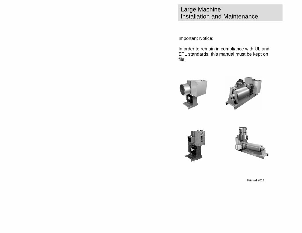
supplied with the machine to provide control for the machine. These machines sometimes switch full motor current and voltage through the remote control toggle switch and thus require that proper size and type wire be installed from the machine to the remote control location. Only one remote control switch may be used with these machines. All DC and TV machines are equipped with an MCS control circuit (described within) to provide a standard user interface. On DC Models the MCS control circuit engages the input of an independent DC drive board which powers the DC motor directly via integral output devices. The DC drive board also provides the following options for the machine (please see drawings E-DCLV120-95 & E-RCSDC-98 which follow): • Variable speed operation • Maximum obtainable speed • Minimum obtainable speed • Deceleration ramp (If equipped for such) • Acceleration ramp • IR compensation • Dynamic braking
Please note some of these options require additional control hardware which must be ordered separately. DC machines can use only one (1) speed control potentiometer either remotely or locally located. However, any number of RCS-1 (OPEN, CLOSE, STOP) remote control stations may be used with these machines. On TV Models the MCS control circuit engages the input of an independent AC frequency drive controller which powers the inverter duty three-phase motor directly. The frequency drive controller can provide the following options for the machine:
• Variable speed operation (during installation only) • Maximum obtainable speed • Minimum obtainable speed • Deceleration ramp
Automatic Devices Company Page -47 2121 South 12th Street Allentown, PA 18103 800 360-2321
Automatic Devices Company Page -46 2121 South 12th Street Allentown, PA 18103 800 360-2321
Automatic Devices Company Page -7 2121 South 12th Street Allentown, PA 18103 800 360-2321
• Acceleration ramp TV machines can use only one (1) speed control potentiometer either remotely or locally located. However, any number of RCS-1 (OPEN, CLOSE, STOP) remote control stations may be used with these machines. Instructions are provided in this manual for the installation, maintenance, troubleshooting and repair of both types of curtain machines. Standard schematic wiring diagrams are provided and are detailed to show control function, rather than precise electrical connections.
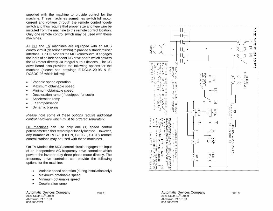
1D. RECEIVING, HANDLING AND STORAGE: Handle and unpack the machine carefully. Do not pick up the machine by the control enclosure, limit switch, nor by any parts extending from the unit. Use the supporting base and/or the frame for handling the unit. Immediately upon arrival, check the shipment for concealed damage and make certain that the remote control station, and other items if ordered, are included. Any damage or missing items should be reported as soon as possible as outlined in 1B. Equipment which will not be installed immediately should be stored in a clean dry location. Caution should be taken to prevent moisture, dust and dirt from accumulating in storage and installation areas.
2A. MOUNTING:
This curtain machine is designed to be mounted vertically, base down, using the mounting holes provided in the base. The machine is normally mounted beneath the live-end pulley of the curtain track. The curtain machine can be mounted in other locations, such as above the track, or
2. MACHINE INSTALLATION AND START-UP

Automatic Devices Company Page -8 2121 South 12th Street Allentown, PA 18103 800 360-2321
off to one side, but additional pulleys are required for other than the normal location described above. Wherever the machine is located, it is important that the operating cables are properly aligned so that they do not bind, or rub against the sides of the pulleys or against any other objects. The machine must also be located a distance from the last pulley that will keep the fleet angle of the operating cord to less than 2 degrees. For most curtain track systems with a travel of 60 feet or less, this minimum distance is 14 feet. IMPORTANT: THE ME-1 METAL MACHINE GUARD SUPPLIED WITH THE MACHINE MUST BE INSTALLED IN ORDER FOR MACHINE TO REMAIN IN COMPLIANCE WITH UL STANDARDS.
2B. WIRING:
Provide adequate service for the current rating of the machine as indicated on its nameplate. A separate branch circuit for each machine is recommended. Control wiring should be sized according to the type of machine being used. MCS and DC machines are designed such that the control switches engage electrical relays and thus the maximum inrush power is limited to 85 VA or less. Non-MCS machines switch full motor current and voltage and require larger control wires than the MCS models. MCS, TV and DC machines are equipped with low-voltage control (LVCS) which lowers the control voltage of the machine to 24 Vac. Note: Some machines’ control circuits are Class 2 circuits and must be wired according to NEC standards for Class 2 circuits.
All curtain machines must be grounded. A green ground terminal is provided within the control enclosure for this purpose. Make certain that the proper voltage is connected to the unit. Do not use an extension cord to provide power to the unit since this will result in a voltage drop to the machine which may cause erratic operation. Check the
Automatic Devices Company Page -45 2121 South 12th Street Allentown, PA 18103 800 360-2321

Automatic Devices Company Page -44 2121 South 12th Street Allentown, PA 18103 800 360-2321
Automatic Devices Company Page -9 2121 South 12th Street Allentown, PA 18103 800 360-2321
identification plate of the machine for voltage requirements.
2C. START-UP: Before applying power, make certain that all parts are free moving and that, if the drum or sprocket rotates, it will not accidentally engage some nearby object or person. It is suggested that initial start-up be done without cable attached to the drum or chain to the sprocket, so that should problems arise, they would not incur no damage to the system. If the track system is rigged to the machine upon arrival, before operating the machine, make certain the master carriers of the track system are not attached to the operating cables, or are in a location in the track which will enable them to move a short distance without binding or causing damage. Instructions for attachment of the cable to the drum or chain to the sprocket are included elsewhere in this manual. With power applied to the machine, and the unit either not connected to the track system, clear of obstructions or connected to the track’s cables in a manner that will allow unimpeded movement, press either the "OPEN" or "CLOSE" push-button of the MCS or DC machine, or engage the toggle switch operator of the non-MCS machine. The drum or sprocket of the machine should rotate. Pressing the "STOP" push-button (red) of the MCS or DC machine or centering the toggle switch of a non-MCS machine should stop all movement. The unit should operate in the opposite direction when the remaining push-button is pressed, or the toggle switch is thrown in the opposite direction after the machine has stopped. With MCS and DC machines, electrical interlocks prevent reversal while the machine it is operating.
NOTE: Adjustments to the limit switches must be done with power removed from the machine. Adjustments to DC drive potentiometers must be done with power applied to the machine.
Automatic Devices Company Page -10 2121 South 12th Street Allentown, PA 18103 800 360-2321
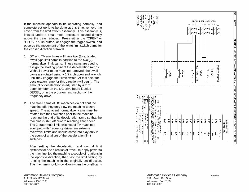
If the machine appears to be operating normally, and complete set up is to be done at this time, remove the cover from the limit switch assembly. This assembly is, located under a small metal enclosure located directly above the gear reducer. Press either the "OPEN" or "CLOSE" push-button, or engage the toggle switch, and observe the movement of the white limit switch cams for the chosen direction of travel. 1. DC and TV machines will have two (2) extended
dwell type limit cams in addition to the two (2) normal dwell limit cams. These cams are used to assign the starting point of the deceleration ramps. With all power to the machine removed, the dwell cams are rotated using a 1/2 inch open end wrench until they engage their limit switch. At this point the deceleration ramp for this direction will begin. The amount of deceleration is adjusted by a trim potentiometer on the DC drive board labeled DECEL, or in the programming section of the frequency drive.
2. The dwell cams of DC machines do not shut the
machine off, they only slow the machine to zero speed. The adjacent normal dwell cams must be rotated into their switches prior to the machine reaching the end of its deceleration ramp so that the machine is shut off prior to reaching zero speed. The 2 outer most limit switches of TV machines equipped with frequency drives are extreme overtravel limits and should come into play only in the event of a failure of the deceleration limit switches.
After setting the deceleration and normal limit switches for one direction of travel, re-apply power to the machine, jog the machine a couple of rotations in the opposite direction, then test the limit setting by running the machine in the originally set direction. The machine should slow down when the dwell cams
Automatic Devices Company Page -43 2121 South 12th Street Allentown, PA 18103 800 360-2321

Automatic Devices Company Page -42 2121 South 12th Street Allentown, PA 18103 800 360-2321
Automatic Devices Company Page -11 2121 South 12th Street Allentown, PA 18103 800 360-2321
engage their switches and then stop when normal dwell limits activate their switches. Repeat steps 1 & 2 for the other direction of travel. If the unit operates satisfactorily in both directions, it is ready to be connected to the cords or chains operating the track.
The limit switches may require final adjustment after the cords or chains are attached to the machine.
3A. RIGGING A GROOVED CABLE DRUM MACHINE:
(Note: video instructions are available online at www.automaticdevices.com)
A plumb line should be run from the center point of the live-end pulley to the drum to make certain that the drum is vertically in line with the live-end pulley. Drum machines must never be closer than 14 feet from track live-end pulley or last muling pulley of the system. Place the coil of cable on the floor beneath the live-end (double wheeled) pulley. Thread one end of the cable over one wheel of the live-end pulley, through the master carrier of the track system (live-end half) and continue along the track to the dead-end pulley, go around the dead-end pulley through the remaining master carrier (dead-end half), back along the other half of the track and down to the machine; then pull about five feet of extra cable. Do not cut the cable. If the machine is equipped with a driving dog, disengage the drum from drive shaft by backing out the thumb screw of the driving dog. If the machine’s drum is directly attached to the gear reducer’s output shaft, you can loosen the set screw in the drum and back out the key to allow the drum to spin freely. Thread the end of
3. CABLE ATTACHMENT

Automatic Devices Company Page -12 2121 South 12th Street Allentown, PA 18103 800 360-2321
cable from the remainder of the coil through the hole in one end of the drum and fasten it on the inside of drum with a cord connector. Wind the cable on the drum (following the grooves carefully) to within THREE grooves of the other end of drum. This is called “loading the drum”. Then pull out any excess cable with the other end of the cable. Wind three wraps on the remaining end of the drum in the opposite direction of the loaded cable, and feed its end through the hole at the end of the drum and secure it with a cord connector. Cut off any excess cable. Re-engage the drum by turning in thumb screw or tightening the set screw.
3B. RIGGING SPROCKET DRIVE MACHINES:
A plumb line should be dropped from the center point of the live-end pulley of the track system to the sprocket of the machine in order to make certain that the sprocket is vertically in line with the live-end pulley. The sprocket drive machine must never be closer to the track live-end pulley than the amount of travel, plus a minimum additional 12 inches. Place the coil of cable beneath the live-end (double) pulley. Thread one end of cable over one wheel of pulley, through a master carrier of the live-end half of the track system, and continue along the track to the dead-end pulley, continue around the dead-end pulley and back along the other half of the track though the remaining
IMPORTANT NOTE: All wire-centered cable stretches during its first few weeks of use. Therefore, it is imperative that excess slack be taken out of the system at the machine drum. If this is not done, it’s possible for the cable to slip off the drum and wrap around the gear reducer’s output shaft causing serious operational difficulties and potentially catastrophic damage to the system. It is strongly recommended that during the first three weeks of operation, periodic checks be made to assure that excess slack in the cord has been eliminated.
DO NOT ATTEMPT TO USE LARGER CABLE THAN SPECIFIED.
Automatic Devices Company Page -41 2121 South 12th Street Allentown, PA 18103 800 360-2321
Automatic Devices Company Page -40 2121 South 12th Street Allentown, PA 18103 800 360-2321
Automatic Devices Company Page -13 2121 South 12th Street Allentown, PA 18103 800 360-2321
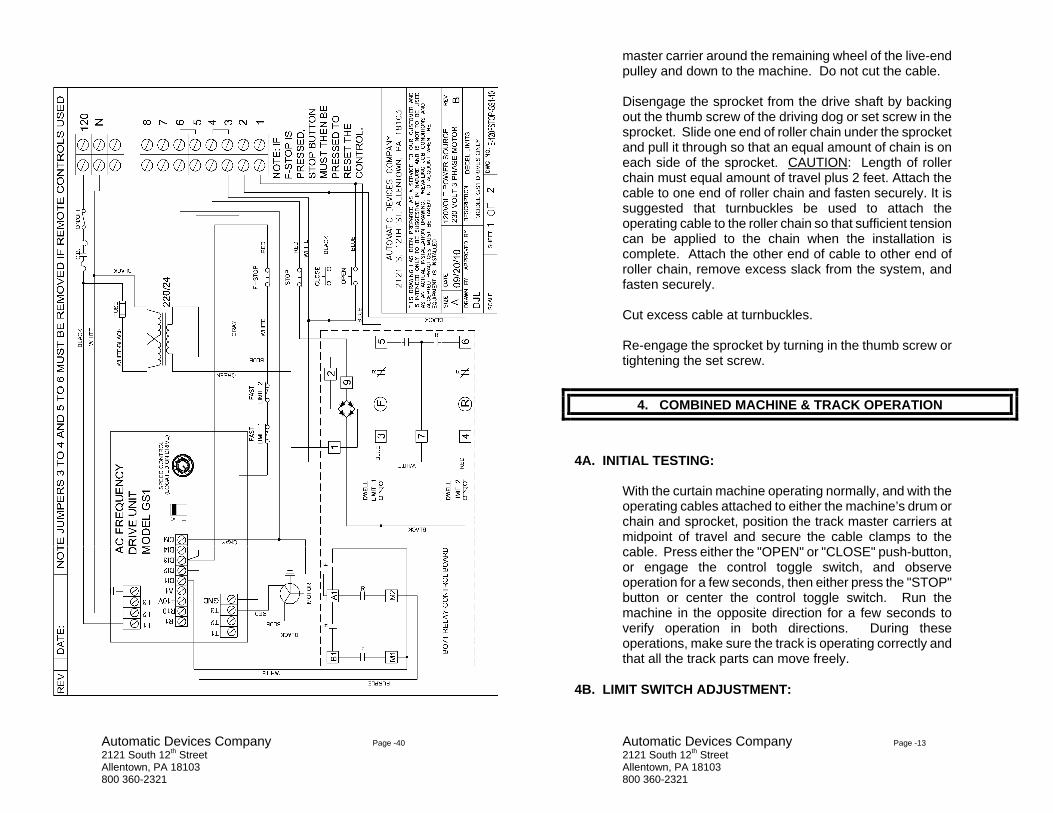
master carrier around the remaining wheel of the live-end pulley and down to the machine. Do not cut the cable. Disengage the sprocket from the drive shaft by backing out the thumb screw of the driving dog or set screw in the sprocket. Slide one end of roller chain under the sprocket and pull it through so that an equal amount of chain is on each side of the sprocket. CAUTION: Length of roller chain must equal amount of travel plus 2 feet. Attach the cable to one end of roller chain and fasten securely. It is suggested that turnbuckles be used to attach the operating cable to the roller chain so that sufficient tension can be applied to the chain when the installation is complete. Attach the other end of cable to other end of roller chain, remove excess slack from the system, and fasten securely. Cut excess cable at turnbuckles. Re-engage the sprocket by turning in the thumb screw or tightening the set screw.
4A. INITIAL TESTING:
With the curtain machine operating normally, and with the operating cables attached to either the machine’s drum or chain and sprocket, position the track master carriers at midpoint of travel and secure the cable clamps to the cable. Press either the "OPEN" or "CLOSE" push-button, or engage the control toggle switch, and observe operation for a few seconds, then either press the "STOP" button or center the control toggle switch. Run the machine in the opposite direction for a few seconds to verify operation in both directions. During these operations, make sure the track is operating correctly and that all the track parts can move freely.
4B. LIMIT SWITCH ADJUSTMENT:
4. COMBINED MACHINE & TRACK OPERATION

Automatic Devices Company Page -14 2121 South 12th Street Allentown, PA 18103 800 360-2321
With the track and machine operating properly, press either the "OPEN" or "CLOSE" push-button or engage the control toggle switch and allow the curtain to approach that particular end of its travel. While the machine is operating, note the rotational direction of the limit switch cam for the chosen direction of travel. If the limit switch does not stop the machine prematurely, press the "STOP" button or center the control toggle switch when the curtain nears its desired position. With a 1/2 inch open end wrench, rotate the appropriate white plastic cam in the noted direction of travel, until it contacts its micro switch arm and a distinct click is heard. Run the machine in the opposite direction for several feet and then repeat the previous step. You can fine tune the limit stop point by rotating the white cam back and forth, and running the machine to check the stop position. While doing this, make sure machine is allowed to obtain its full speed before hitting the limit switch. Also note that a very small amount of turn of the limit cam results in a few inches of actual curtain travel so make very small adjustments. Repeat the above process for the opposite direction.
Note: DC and TV machines are equipped with four (4) limit cams and switches; long dwell cams in addition to normal (shorter) dwell cams normally. The longer dwell cams are used to initiate and maintain the deceleration ramp of the machine and must be rotated to engage their respective limit switches at the point at which the deceleration ramp is to begin and must remain engaged over the complete deceleration ramp.
NOTE THAT ON DC MACHINES THESE LIMITS DO NOT SHUT THE MACHINE OFF. In order to shut the machine off the adjacent shorter dwell limit cams must be rotated to engage its limit switch. Please note that the standard limits must engage their respective limits prior to the end of the deceleration ramp ending in order to shut the machine off. This is not the case with TV machines equipped with frequency drive controls. The shorter dwell limits of these machines are used as extreme overtravel limits and should only come into play in the event of the deceleration limits failing. Engaging the extreme overtravel limits of a TV machine will lockout the operation of the machine and the limit needs to be cleared and the stop button pressed in order for the machine to reset and be able to operate again.
Automatic Devices Company Page -39 2121 South 12th Street Allentown, PA 18103 800 360-2321
Automatic Devices Company Page -38 2121 South 12th Street Allentown, PA 18103 800 360-2321
Automatic Devices Company Page -15 2121 South 12th Street Allentown, PA 18103 800 360-2321
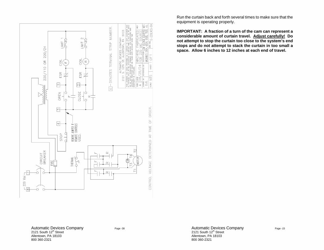
Run the curtain back and forth several times to make sure that the equipment is operating properly.
IMPORTANT: A fraction of a turn of the cam can represent a considerable amount of curtain travel. Adjust carefully! Do not attempt to stop the curtain too close to the system’s end stops and do not attempt to stack the curtain in too small a space. Allow 6 inches to 12 inches at each end of travel.

Automatic Devices Company Page -16 2121 South 12th Street Allentown, PA 18103 800 360-2321
5A. LUBRICATION:
If required, lubricate the motor as per instructions on motor nameplate. Gear reducer is factory filled with 600W super cylinder oil. During average service, the reducer can be considered to be permanently lubricated. If, for some reason, additional lubricant is required, it can be added through an opening at the top of the reducer. The entire limit switch mechanism must be removed in order to add lubricant. Be sure to remove power from the machine prior to performing maintenance on the machine. Roller chain drives, such as those used on the limit switch and on sprocket drive curtain machines, should occasionally be lightly oiled. Remove power from the machine prior to oiling.
5B. ADJUSTMENTS: As explained previously, all wire-centered cable stretches and this slack must be removed from the system in order to prevent mis-wrapping of the cable on the drum. Follow instructions in Paragraphs 3A and 3B for removal of slack cable. If the machine is equipped with a V-belt drive, the belt will stretch somewhat over time and must be adjusted so that the belt cannot slip. To check the adjustment of the V-belt, remove and lockout the power the machine’s power source. Remove the belt guard covering the motor and gear pulleys. If the belt needs to be adjusted, loosen the four hex nuts under the motor base (not the machine base) one or two turns. Then tighten the four hex nuts above the motor base the same number of turns. If the belt is still loose, repeat the procedure. When the belt is properly adjusted, replace belt guard and reapply power to the machine.
5. MAINTENANCE
Automatic Devices Company Page -37 2121 South 12th Street Allentown, PA 18103 800 360-2321

Automatic Devices Company Page -36 2121 South 12th Street Allentown, PA 18103 800 360-2321
Automatic Devices Company Page -17 2121 South 12th Street Allentown, PA 18103 800 360-2321
To tighten the limit switch roller chain, remove and lockout the machine’s power source. Remove the chain guard covering the gear and limit switch sprockets. If the chain is slack, loosen (slightly) the two cap screws holding the limit switch bracket to the gear housing. Tap the bracket upward lightly until the chain appears normal. Tighten cap screws, replace the chain guard and restore power to the machine.
5C. CLEANING: With power off, remove debris and foreign objects from the vicinity of the curtain machine, from between the motor and base, the motor and frame, and also from the vicinity of drum. Low-pressure air or a vacuum cleaner can be used for this purpose. With power off and the source of power locked out, remove the cover from the control enclosure. Remove dust and dirt from inside the control box with low-pressure air or a vacuum cleaner, being careful not to damage any internal parts or loosen any wires. Check and tighten all connections and mounting screws. Replace the control box cover. Repeat procedure for the limit switch assembly. Once cleaning is complete and the covers have been replaced, restore power to the machine.

Automatic Devices Company Page -18 2121 South 12th Street Allentown, PA 18103 800 360-2321
SEE DRIVE MANUALS FOR INFORMATION ON DC
AND AC DRIVES
The following information should be used when checking and servicing the curtain machines described in this manual. It is assumed that the troubleshooting and repair will be performed by individuals with a basic knowledge of electricity, motor controls, with the ability to follow the wiring diagrams enclosed, and who will take the precautions required when working with exposed electrical connections.
In order to perform the procedures listed, basic hand tools plus measuring and indicating equipment are required. A clamp-on type volt-amp-ohmmeter tester with accessories will provide the necessary indication and measurements. Before proceeding with any of the checks listed below, make certain that all connections are tight and any obviously defective or broken parts are replaced. Also make certain that the track system is operating freely and that the cables are in good condition. The reversing contactor can be replaced as a complete assembly or individual parts, as shown on the enclosed manufacturer's literature, can be obtained as needed.
When ordering replacement parts for this curtain machine, please give a description of the part and also provide the model number and serial number of the machine.
6A. SYMPTOM: MACHINE WILL NOT START
POSSIBLE CAUSE
SUGGESTION
Incoming power switched off
Check disconnect switch and correct
Circuit breaker tripped Reset and test machine operation
Control fuse loose or blown Check and replace with fuse of equal rating
Fuse holder broken Replace with unit of equal valueJumper “X” removed from terminals 3 & 4 and no remote
Replace jumper or connect remote controls
6. TROUBLESHOOTING AND REPAIR
Automatic Devices Company Page -35 2121 South 12th Street Allentown, PA 18103 800 360-2321

Automatic Devices Company Page -34 2121 South 12th Street Allentown, PA 18103 800 360-2321
Automatic Devices Company Page -19 2121 South 12th Street Allentown, PA 18103 800 360-2321
controls connected. Faulty remote control wiring Check remote wiring with DVM
for open, shorted or mis-wiring. Faulty ESR board Check relay contacts with DVM
Check relay operation by pressing open or close button
Faulty limit switch Check limit switches with DVM POWER REMOVED FROM MACHINE
Both limit switches activated Rotate one of the cams off of one of the limit switches
Defective STOP pushbutton Check with DVM POWER REMOVED FROM MACHINE
6B. SYMPTOM: MACHINE RUNS IN ONE DIRECTION ONLY
POSSIBLE CAUSE
SUGGESTION
Defective Pushbutton Check operation with meter (power removed) and replace if necessary
Defective Mechanical Interlock
Check mechanical operation of the contactor (power removed) and replace contactor if defective.
Limit Switch Activated Rotate plastic limit cam off of the switch (power off) for the direction in question.
Defective Limit Switch Check continuity of switch with power removed, and replace if defective.
Defective Contactor Coil
Check with meter and replace contactor if necessary.
Faulty ESR board or relay Check relay contacts with DVM And power removed from machine. Contacts should be normally closed.
Foreign material in contactor With power removed, check for foreign material that may be preventing contactor from

Automatic Devices Company Page -20 2121 South 12th Street Allentown, PA 18103 800 360-2321
operating. Clear or replace contactor.
6C. SYMPTOM: MOTOR RUNS BUT OUTPUT SHAFT DOES NOT TURN
POSSIBLE CAUSE
SUGGESTION
Broken or loose V-belt Adjust or replace belt. Broken or loose belt pulley Check set screws and drive
keys of pulleys and shafts. Tighten or replace as necessary.
Loose thumb screw or set screw in driving dog.
Align correctly with hole in drum, spool or sprocket and tighten.
6D. SYMPTOM: NOISY MACHINE
POSSIBLE CAUSE
SUGGESTION
Loose motor belts Loosen motor mounting bolts and slide motor to apply tension to the belt. Re-secure motor mounting bolts.
Dry gear reducer Check oil level of gear reduction unit. If oil level is low, replace oil with 600w gear oil.
Broken or loose pulley Check set screws and keys. Replace and tighten as necessary.
Pulley rubbing against protective guard
Loosen Allen set screw in the pulleys, slide them back on their drive shafts, check key alignment and re-tighten Allen set screws.
Loose thumb or set screw in driving dog
Align hole in drum or sprocket with thumb or set screw and tighten.
Machine mounting bolts are loose.
Check mounting hardware and tighten as needed.
Automatic Devices Company Page -33 2121 South 12th Street Allentown, PA 18103 800 360-2321
Automatic Devices Company Page -32 2121 South 12th Street Allentown, PA 18103 800 360-2321
• Not all of the parameters available on the frequency drive can be used with the machine. Verify that the parameter being changed or added, will work with the machine provided.
• The machine provides its own control signal. Do not input
any outside control voltage or control signal to the machine.
Automatic Devices Company Page -21 2121 South 12th Street Allentown, PA 18103 800 360-2321
6E. SYMPTOM: MACHINE STARTS BUT WILL NOT PULL LOAD
POSSIBLE CAUSE
SUGGESTION
Wrong incoming voltage
Check voltage level at input terminals under load. Voltage must be +/- 10% of rated voltage.
Extension cord is being used to provide power.
Remove extension cord and hardwire with correct size and type wire.
Broken or loose V-belt Loosen motor mounting bolts and slide motor to apply tension to the belt. Re-secure motor mounting bolts. If belt is torn or worn out, replace with like unit.
Broken or loose pulley Check set screws and keys. Replace and tighten as necessary.
Dry gear reducer
Check oil level of gear reduction unit. If oil level is low, replace oil with 600w gear oil.
Defective motor capacitor Check capacitor with DVM and replace with like unit if needed.
Track system is not assembled correctly
Check operation of track without machine drive. Verify assembly with instructions provided with track system.
Operating cable too tight Cable should be taught, but not overly tight as this will increase the static load on the machine. If necessary, remove some tension at the machine’s drum.
6F. SYMPTOM: CIRCUIT BREAKER TRIPS
POSSIBLE CAUSE
SUGGESTION
Wrong incoming voltage Check voltage level at input

Automatic Devices Company Page -22 2121 South 12th Street Allentown, PA 18103 800 360-2321
terminals under load. Voltage must be +/- 10% of rated voltage.
Extension cord is being used to provide power.
Remove extension cord and hardwire with correct size and type wire.
Broken or loose V-belt Loosen motor mounting bolts and slide motor to apply tension to the belt. Re-secure motor mounting bolts. If belt is torn or worn out, replace with like unit.
Broken or loose pulley Check set screws and keys. Replace and tighten as necessary.
Dry gear reducer
Check oil level of gear reduction unit. If oil level is low, replace oil with 600w gear oil.
Defective motor capacitor Check capacitor with DVM and replace with like unit if needed.
Defective motor Check if motor shaft spins freely. Also, check continuity of the motor windings.
Track system is not assembled correctly
Check operation of track without machine drive. Verify assembly with instructions provided with track system.
Operating cable too tight Cable should be taught, but not overly tight as this will increase the static load on the machine. If necessary, remove some tension at the machine’s drum.
6G. SYMPTOM: CONTROL FUSE BLOWS
POSSIBLE CAUSE
SUGGESTION
Wrong incoming voltage
Check voltage level at input terminals under load. Voltage must be +/- 10% of rated voltage.
Extension cord is being used to provide power.
Remove extension cord and hardwire with correct size and
Automatic Devices Company Page -31 2121 South 12th Street Allentown, PA 18103 800 360-2321
Note that depending on the type of drive used, it may be necessary to use a personal computer or user interface module to program the drive.
MACHINES EQUIPPED WITH “FAST STOP” LOOPS If the control circuit includes a “Fast Stop” loop in addition to the standard stop loop the machine will need to be electrically reset after the “Fast Stop” circuit has been activated. Simply press the standard Stop pushbutton on the machine or remote control to reset the machine.
TECHNICAL NOTES:
• Model “TV” machines are equipped with inverter duty
motors. Do not replace the motor with a standard duty 3-phase motor.
• It is suggested that the machine’s frequency be limited to 60
hertz in order to prevent premature wear of the machine and track components.
• If deceleration ramps are used, verify that the machine
shuts off prior to the end of the dwell limit cams. If the limit cams release the limit switch during operation the machine will accelerate and continue to run.
• The frequency drive is sized according to the horsepower
and voltage of the machine’s motor. Do not use a motor of any other horsepower or voltage.
• In most cases the frequency drive’s programming section is
password protected. A default password is installed at the factory and can be found in the documentation provided with the machine. It is suggested that the password be changed to a user specific password, once the machine installation is complete.
IMPORTANT: IF THE MACHINE IS EQUIPPED WITH DECELERATION LIMIT SWITCHES AND A DECELERATION RAMP, THE MACHINE WILL DECELERATE TO A STOP WHEN THE STOP PUSHBUTTON IS PRESSED AND WILL NOT COME TO IMMEDIATE STOP. THE DECELERATION TIME IS EQUAL TO TIME SET FOR THE DECELERATION LIMIT SWITCHES.

Automatic Devices Company Page -30 2121 South 12th Street Allentown, PA 18103 800 360-2321
All field wiring is connected to a barrier type terminal strip located inside of the machine’s control box. The strip(s) positions are labeled. All curtain machines must be grounded. A ground terminal is provided in the control box. Provide a properly sized electrical service for the voltage and current draw of the machine. Though these machines are equipped with 3-phase inverter duty motors, the machine(s) can be fabricated for input voltage sources of; 120 VAC, 220 VAC single phase, 208/220 VAC three phase and 460 VAC three phase. Specifications for the voltage, current, and frequency for the machine can be found on the ADC serial number plate located on the machine’s control box cover. A separate branch circuit for each machine is suggested. In most cases the control circuit is a Class 2 circuit and must be wired accordingly. In most cases the remote control station(s) will operate control relays located in the machine’s control box. Depending on the type of relays used, the control circuit could see a maximum inrush load of 100 VA. If the machine has remotely located speed, fault, indication, etc. controls or indicators please see the manual and schematic provided with the machine for specifications on these circuits.
PROGRAMMING Model “TV” machines are furnished with a wide variety of control circuits and thus the drives are provided with a wide variety of programs. Each machine is furnished programmed with a basic set of parameters from the factory. These parameters, as well as the rest of the drive parameters, can be reprogrammed in the field to meet the project specifications. To reprogram the drive please see the manual for the frequency drive controller that was furnished with the machine.
IMPORTANT: REPROGRAMMING THE FREQUENCY DRIVE UNIT PARAMETERS CAN RESULT IN THE MACHINE OPERATION BEING OUTSIDE OF THE MECHANICAL LIMITS OF THE TRACK OR LIFT SYSTEM. BE SURE TO CHECK POSSIBLE CONFLICTS WITH THE MECHANICAL SYSTEM PRIOR TO MAKING ANY CHANGES TO THE DRIVE PROGRAM.
Automatic Devices Company Page -23 2121 South 12th Street Allentown, PA 18103 800 360-2321
type wire. Faulty remote control wiring Compare remote control circuit
wiring with schematic provided with the machine. Check all connection and junction points for loose or exposed wires.
Loose connection in the control box.
Remove power from the machine and tighten all connections on contactor and terminal strips.
Wrong type fuse is being used.
Verify the correct type (MDX, MLX) and amperage fuse is being used in the control circuit.
Defective mechanical interlock on contactor
With power removed from machine, check mechanical operation of contactor and replace if the unit is jammed.
Track system is not assembled correctly
Check operation of track without machine drive. Verify assembly with instructions provided with track system.
Operating cable too tight Cable should be taught, but not overly tight as this will increase the static load on the machine. If necessary, remove some tension at the machine’s drum.
6H. SYMTOM: MACHINE WILL NOT STOP AT LIMIT SETTING
POSSIBLE CAUSE
SUGGESTION
Faulty remote control wiring Compare remote control circuit wiring with schematic provided with the machine. Check all connection and junction points for loose or exposed wires.
Pushbuttons or control contacts are defective
Check operation with DVM. Contacts must be normally open, momentary operation.
Faulty remote control wiring Compare remote control circuit wiring with schematic provided with the machine. Check all

Automatic Devices Company Page -24 2121 South 12th Street Allentown, PA 18103 800 360-2321
connection and junction points for loose or exposed wires.
Loose connection in the control box.
Remove power from the machine and tighten all connections on contactor and terminal strips.
Loose or missing limit switch chain
Verify the chain from the gear reducer output shaft to the limit switch is intact and has sufficient tension.
Loose limit switch sprocket Check set screw, Woodruff key and shaft of limit switch assembly and confirm all are correctly secured and operating freely.
Defective limit switch cam springs
The limit switch tripping cams are held in place by spring tension via spring washers. If the cams turn freely about the shaft, the cam assembly needs to be replaced.
6I. SYMPTOM: MOTOR OVERHEATS
POSSIBLE CAUSE
SUGGESTION
Wrong incoming voltage
Check voltage level at input terminals under load. Voltage must be +/- 10% of rated voltage.
Extension cord is being used to provide power.
Remove extension cord and hardwire with correct size and type wire.
Faulty remote control wiring Compare remote control circuit wiring with schematic provided with the machine. Check all connection and junction points for loose or exposed wires.
Loose connection in the control box.
Remove power from the machine and tighten all connections on contactor and terminal strips.
Defective mechanical interlock With power removed from
Automatic Devices Company Page -29 2121 South 12th Street Allentown, PA 18103 800 360-2321
MACHINES EQUIPPED WITH
FREQUENCY DRIVE CONTROLLERS MODEL NUMBERS ENDING WITH “TV”
DESCRIPTION:
Model “TV” machines are fabricated with electronic frequency control modules which allow the user to set various operating parameters for the machine in the field. The machines are fabricated in a variety of styles and use a variety of frequency drive types. Each machine is shipped with a programming and operating manual specific to the model controller used. Various control circuits are provided with these machines. Basic models offer start/stop/reverse pushbutton operation with analog referenced speed signals. This manual provides an overview of basic machine operation and parts. Please see the drive manual and electrical schematic provided with the machine for information on programming or operating the machine. BASIC INSTALLATION: See Sections 2 through 5 of this manual. WIRING: NOTE: ALL WIRING TO AND FROM THE MACHINE MUST BE DONE IN ACCORDANCE WITH NATIONAL AND LOCAL ELECTRICAL CODES.
IMPORTANT: Prior to operating the machine, make sure the area around the machine and the track or other output device is clear of obstructions and that no personnel can come in contact with any of the moving equipment of the machine and the output device(s).
IMPORTANT: 120/208/220/460 Vac potentials are present on the frequency drive units as well as elsewhere in the control box.

Automatic Devices Company Page -28 2121 South 12th Street Allentown, PA 18103 800 360-2321
1. Start the drive and set the speed control knob to the
speed at which regulation is most critical in your particular application. Adjust the motor load to minimum and then measure the motor speed precisely with a hand tachometer or a strobe light.
2. Now adjust the motor load to maximum (not exceeding
100% rated torque) and again read motor speed. 3. If the "maximum load" speed is less than the "minimum
load" speed, turn the IR COMPENSATION POTENTIOMETER clockwise until they are equal. There is no need to wait for the motor to warm up since the IR compensation works equally at any motor temperature. Some loads may "hunt" if the IR compensation is set too high. Turning the IR compensation potentiometer counterclockwise would eliminate this hunting condition.
Automatic Devices Company Page -25 2121 South 12th Street Allentown, PA 18103 800 360-2321
on contactor machine, check mechanical operation of contactor and replace if the unit is jammed.
Track system is not assembled correctly
Check operation of track without machine drive. Verify assembly with instructions provided with track system.
Operating cable too tight Cable should be taught, but not overly tight as this will increase the static load on the machine. If necessary, remove some tension at the machine’s drum.
6J. SYMPTOM: MOTOR STOPS PREMATURELY
POSSIBLE CAUSE
SUGGESTION
Wrong incoming voltage
Check voltage level at input terminals under load. Voltage must be +/- 10% of rated voltage.
Extension cord is being used to provide power.
Remove extension cord and hardwire with correct size and type wire.
Defective Stop push button or contact
Verify operation of button or contact. Must be normally closed momentary operation.
Loose connection in the control box.
Remove power from the machine and tighten all connections on contactor and terminal strips.
Track system is not assembled correctly
Check operation of track without machine drive. Verify assembly with instructions provided with track system.
Operating cable too tight Cable should be taught, but not overly tight as this will increase the static load on the machine. If necessary, remove some tension at the machine’s drum.
Automatic Devices Company Page -26 2121 South 12th Street Allentown, PA 18103 800 360-2321
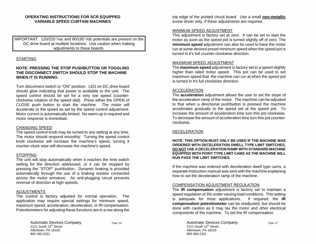
OPERATING INSTRUCTIONS FOR SCR EQUIPPED VARIABLE SPEED CURTAIN MACHINES
STARTING NOTE: PRESSING THE STOP PUSHBUTTON OR TOGGLING THE DISCONNECT SWITCH SHOULD STOP THE MACHINE WHEN IT IS RUNNING. Turn disconnect switch to "ON" position. LED on DC drive board should glow indicating that power is available to the unit. The speed control should be set for a very low speed (counter-clockwise rotation of the speed dial). Press either the OPEN of CLOSE push button to start the machine. The motor will accelerate to the speed as set by the speed control adjustment. Motor current is automatically limited. No warm-up is required and motor response is immediate. CHANGING SPEED The speed control knob may be turned to any setting at any time. The motor should respond smoothly. Turning the speed control knob clockwise will increase the machine's speed, turning it counter-clock wise will decrease the machine's speed.
STOPPING The unit will stop automatically when it reaches the limit switch setting for the direction addressed, or it can be stopped by pressing the "STOP" pushbutton. Dynamic braking is provided automatically through the use of a braking resistor connected across the motor armature. An anti-plugging circuit prevents reversal of direction at high speeds. ADJUSTMENTS The control is factory adjusted for normal operation. The application may require special settings for minimum speed, maximum speed, acceleration, deceleration, or IR compensation. Potentiometers for adjusting these functions are in a row along the
IMPORTANT: 120/220 Vac and 90/180 Vdc potentials are present on the DC drive board at multiple locations. Use caution when making
adjustments to these boards.
Automatic Devices Company Page -27 2121 South 12th Street Allentown, PA 18103 800 360-2321
top edge of the printed circuit board. Use a small non-metallic screw driver only, if these adjustments are required. MINIMUM SPEED ADJUSTMENT This adjustment is factory set at zero. It can be set to start the motor as soon as the speed pot is turned slightly off of zero. The minimum speed adjustment can also be used to have the motor run at some desired preset minimum speed when the speed pot is turned in it's full counter-clockwise direction. MAXIMUM SPEED ADJUSTMENT The maximum speed adjustment is factory set to a speed slightly higher than rated motor speed. This pot can be used to set maximum speed that the machine can run at when the speed pot is turned in it's full clockwise direction. ACCELERATION The acceleration adjustment allows the user to set the slope of the acceleration ramp of the motor. The machine can be adjusted to that when a directional pushbutton is pressed the machine accelerates gradually to the speed set at the speed pot. To increase the amount of acceleration time turn this pot clockwise. To decrease the amount of acceleration time turn this pot counter-clockwise.
DECELERATION
NOTE: THIS OPTION MUST ONLY BE USED IF THE MACHINE WAS ORDERED WITH DECELERATION DWELL TYPE LIMIT SWITCHES. DO NOT USE A DECELERATION RAMP WITH STANDARD MACHINE EQUIPPED WITH POINT TYPE LIMIT CAMS AS THE MACHINE WILL RUN PASS THE LIMIT SWITCHES.
If the machine was ordered with deceleration dwell type cams, a separate instruction manual was sent with the machine explaining how to set the deceleration ramp of the machine.
COMPENSATION ADJUSTMENT REGULATION The IR compensation adjustment is factory set to maintain a speed regulation of 3% under varying load conditions. This setting is adequate for most applications. If required, the IR compensation potentiometer can be readjusted, but should be done with caution as it may tax the motor and other electrical components of the machine. To set the IR compensation: